US11754221B2 - Security apparatus for a golf launch monitor - Google Patents
Security apparatus for a golf launch monitor Download PDFInfo
- Publication number
- US11754221B2 US11754221B2 US17/554,535 US202117554535A US11754221B2 US 11754221 B2 US11754221 B2 US 11754221B2 US 202117554535 A US202117554535 A US 202117554535A US 11754221 B2 US11754221 B2 US 11754221B2
- Authority
- US
- United States
- Prior art keywords
- mount
- guide member
- security apparatus
- launch monitor
- surface features
- Prior art date
- Legal status (The legal status is an assumption and is not a legal conclusion. Google has not performed a legal analysis and makes no representation as to the accuracy of the status listed.)
- Active
Links
- 230000008878 coupling Effects 0.000 claims description 14
- 238000010168 coupling process Methods 0.000 claims description 14
- 238000005859 coupling reaction Methods 0.000 claims description 14
- 238000004873 anchoring Methods 0.000 claims description 4
- 238000012544 monitoring process Methods 0.000 description 15
- 230000001681 protective effect Effects 0.000 description 5
- 238000011161 development Methods 0.000 description 2
- 238000009434 installation Methods 0.000 description 2
- 239000000463 material Substances 0.000 description 2
- 230000007246 mechanism Effects 0.000 description 2
- 239000004417 polycarbonate Substances 0.000 description 2
- 229920000515 polycarbonate Polymers 0.000 description 2
- 229910000831 Steel Inorganic materials 0.000 description 1
- HCHKCACWOHOZIP-UHFFFAOYSA-N Zinc Chemical compound [Zn] HCHKCACWOHOZIP-UHFFFAOYSA-N 0.000 description 1
- 229910052782 aluminium Inorganic materials 0.000 description 1
- XAGFODPZIPBFFR-UHFFFAOYSA-N aluminium Chemical compound [Al] XAGFODPZIPBFFR-UHFFFAOYSA-N 0.000 description 1
- 230000008901 benefit Effects 0.000 description 1
- 230000008859 change Effects 0.000 description 1
- 238000013507 mapping Methods 0.000 description 1
- 229910052751 metal Inorganic materials 0.000 description 1
- 239000002184 metal Substances 0.000 description 1
- 238000012986 modification Methods 0.000 description 1
- 230000004048 modification Effects 0.000 description 1
- 239000004033 plastic Substances 0.000 description 1
- 230000000717 retained effect Effects 0.000 description 1
- 239000010959 steel Substances 0.000 description 1
- 238000012360 testing method Methods 0.000 description 1
- 229910052725 zinc Inorganic materials 0.000 description 1
- 239000011701 zinc Substances 0.000 description 1
Images


Classifications
-
- F—MECHANICAL ENGINEERING; LIGHTING; HEATING; WEAPONS; BLASTING
- F16—ENGINEERING ELEMENTS AND UNITS; GENERAL MEASURES FOR PRODUCING AND MAINTAINING EFFECTIVE FUNCTIONING OF MACHINES OR INSTALLATIONS; THERMAL INSULATION IN GENERAL
- F16M—FRAMES, CASINGS OR BEDS OF ENGINES, MACHINES OR APPARATUS, NOT SPECIFIC TO ENGINES, MACHINES OR APPARATUS PROVIDED FOR ELSEWHERE; STANDS; SUPPORTS
- F16M13/00—Other supports for positioning apparatus or articles; Means for steadying hand-held apparatus or articles
- F16M13/02—Other supports for positioning apparatus or articles; Means for steadying hand-held apparatus or articles for supporting on, or attaching to, an object, e.g. tree, gate, window-frame, cycle
- F16M13/022—Other supports for positioning apparatus or articles; Means for steadying hand-held apparatus or articles for supporting on, or attaching to, an object, e.g. tree, gate, window-frame, cycle repositionable
-
- F—MECHANICAL ENGINEERING; LIGHTING; HEATING; WEAPONS; BLASTING
- F16—ENGINEERING ELEMENTS AND UNITS; GENERAL MEASURES FOR PRODUCING AND MAINTAINING EFFECTIVE FUNCTIONING OF MACHINES OR INSTALLATIONS; THERMAL INSULATION IN GENERAL
- F16M—FRAMES, CASINGS OR BEDS OF ENGINES, MACHINES OR APPARATUS, NOT SPECIFIC TO ENGINES, MACHINES OR APPARATUS PROVIDED FOR ELSEWHERE; STANDS; SUPPORTS
- F16M11/00—Stands or trestles as supports for apparatus or articles placed thereon ; Stands for scientific apparatus such as gravitational force meters
- F16M11/42—Stands or trestles as supports for apparatus or articles placed thereon ; Stands for scientific apparatus such as gravitational force meters with arrangement for propelling the support stands on wheels
- F16M11/425—Stands or trestles as supports for apparatus or articles placed thereon ; Stands for scientific apparatus such as gravitational force meters with arrangement for propelling the support stands on wheels along guiding means
-
- F—MECHANICAL ENGINEERING; LIGHTING; HEATING; WEAPONS; BLASTING
- F16—ENGINEERING ELEMENTS AND UNITS; GENERAL MEASURES FOR PRODUCING AND MAINTAINING EFFECTIVE FUNCTIONING OF MACHINES OR INSTALLATIONS; THERMAL INSULATION IN GENERAL
- F16M—FRAMES, CASINGS OR BEDS OF ENGINES, MACHINES OR APPARATUS, NOT SPECIFIC TO ENGINES, MACHINES OR APPARATUS PROVIDED FOR ELSEWHERE; STANDS; SUPPORTS
- F16M11/00—Stands or trestles as supports for apparatus or articles placed thereon ; Stands for scientific apparatus such as gravitational force meters
- F16M11/02—Heads
- F16M11/04—Means for attachment of apparatus; Means allowing adjustment of the apparatus relatively to the stand
- F16M11/043—Allowing translations
- F16M11/045—Allowing translations adapted to left-right translation movement
-
- A—HUMAN NECESSITIES
- A63—SPORTS; GAMES; AMUSEMENTS
- A63B—APPARATUS FOR PHYSICAL TRAINING, GYMNASTICS, SWIMMING, CLIMBING, OR FENCING; BALL GAMES; TRAINING EQUIPMENT
- A63B24/00—Electric or electronic controls for exercising apparatus of preceding groups; Controlling or monitoring of exercises, sportive games, training or athletic performances
- A63B24/0003—Analysing the course of a movement or motion sequences during an exercise or trainings sequence, e.g. swing for golf or tennis
-
- A—HUMAN NECESSITIES
- A63—SPORTS; GAMES; AMUSEMENTS
- A63B—APPARATUS FOR PHYSICAL TRAINING, GYMNASTICS, SWIMMING, CLIMBING, OR FENCING; BALL GAMES; TRAINING EQUIPMENT
- A63B69/00—Training appliances or apparatus for special sports
- A63B69/36—Training appliances or apparatus for special sports for golf
-
- F—MECHANICAL ENGINEERING; LIGHTING; HEATING; WEAPONS; BLASTING
- F16—ENGINEERING ELEMENTS AND UNITS; GENERAL MEASURES FOR PRODUCING AND MAINTAINING EFFECTIVE FUNCTIONING OF MACHINES OR INSTALLATIONS; THERMAL INSULATION IN GENERAL
- F16B—DEVICES FOR FASTENING OR SECURING CONSTRUCTIONAL ELEMENTS OR MACHINE PARTS TOGETHER, e.g. NAILS, BOLTS, CIRCLIPS, CLAMPS, CLIPS OR WEDGES; JOINTS OR JOINTING
- F16B23/00—Specially shaped nuts or heads of bolts or screws for rotations by a tool
- F16B23/0007—Specially shaped nuts or heads of bolts or screws for rotations by a tool characterised by the shape of the recess or the protrusion engaging the tool
-
- F—MECHANICAL ENGINEERING; LIGHTING; HEATING; WEAPONS; BLASTING
- F16—ENGINEERING ELEMENTS AND UNITS; GENERAL MEASURES FOR PRODUCING AND MAINTAINING EFFECTIVE FUNCTIONING OF MACHINES OR INSTALLATIONS; THERMAL INSULATION IN GENERAL
- F16B—DEVICES FOR FASTENING OR SECURING CONSTRUCTIONAL ELEMENTS OR MACHINE PARTS TOGETHER, e.g. NAILS, BOLTS, CIRCLIPS, CLAMPS, CLIPS OR WEDGES; JOINTS OR JOINTING
- F16B5/00—Joining sheets or plates, e.g. panels, to one another or to strips or bars parallel to them
- F16B5/06—Joining sheets or plates, e.g. panels, to one another or to strips or bars parallel to them by means of clamps or clips
- F16B5/0607—Joining sheets or plates, e.g. panels, to one another or to strips or bars parallel to them by means of clamps or clips joining sheets or plates to each other
- F16B5/0614—Joining sheets or plates, e.g. panels, to one another or to strips or bars parallel to them by means of clamps or clips joining sheets or plates to each other in angled relationship
-
- F—MECHANICAL ENGINEERING; LIGHTING; HEATING; WEAPONS; BLASTING
- F16—ENGINEERING ELEMENTS AND UNITS; GENERAL MEASURES FOR PRODUCING AND MAINTAINING EFFECTIVE FUNCTIONING OF MACHINES OR INSTALLATIONS; THERMAL INSULATION IN GENERAL
- F16B—DEVICES FOR FASTENING OR SECURING CONSTRUCTIONAL ELEMENTS OR MACHINE PARTS TOGETHER, e.g. NAILS, BOLTS, CIRCLIPS, CLAMPS, CLIPS OR WEDGES; JOINTS OR JOINTING
- F16B9/00—Connections of rods or tubular parts to flat surfaces at an angle
- F16B9/05—Connections of rods or tubular parts to flat surfaces at an angle by way of an intermediate member
- F16B9/054—Connections of rods or tubular parts to flat surfaces at an angle by way of an intermediate member the intermediate member being threaded
Definitions
- This disclosure relates generally to the field of security apparatuses used to secure electronic devices and more specifically a security apparatus used to functionally secure a golf launch monitor.
- the golf launch monitor system generally consists of a golf launch monitor that is used in conjunction with monitoring software.
- the golf launch monitoring system enables the mapping of a player's golf swing, the comparison of different golf swings, and the monitoring of granular changes in a player's golf swing.
- Such golf launch monitoring systems are used in a variety of settings including country clubs, retail outlets, teaching facilities, and equipment development and testing facilities.
- the golf launch monitor In order to use the golf launch monitoring system, the golf launch monitor is positioned at various locations relative to the golfer in order to monitor the golfer's swing at a desired perspective or for specific characteristics. Accordingly, proper use of the golf launch monitoring system requires the ability to move the launch monitor to accommodate different golfer's and to collect different data from the same golfer. The data collected by the golf launch monitor is transmitted to a remote processor where it can be compiled and analyzed by a software application.
- While these golf launch monitoring systems are incredibly power practice tools that can improve a golfer's game, these systems and specifically the launch monitors themselves, are very expensive, which makes them a prime target for theft.
- the launch monitor is usually removed from the practice area in between uses and locked away in a secure place. This requires additional time to setup the launch monitoring system in between uses as the launch monitor must be obtained from the secure place, connected to the processor (either wirelessly or via a hard connection), and repositioned in the monitoring area.
- the monitoring area itself may be a secured place that is locked when not in use. This requires additional security measures such as the hardware to secure the monitoring area (e.g., locks on doors/windows) and an access protocol to determine which individuals will have access to the monitoring area.
- An embodiment of a security apparatus for a launch monitor comprises a guide member extending from a first end to a second end.
- the guide member includes a top surface defining one or more top surface features and opposing side surfaces defining one or more side surface features.
- the security apparatus further includes a mount including a mount body extending along a plane that intersects a vertical axis at an angle.
- the mount has a top body surface and a bottom body surface.
- a plurality of clamp members are positioned on a top body surface and each include a retainer configured to retain and secure a portion of the launch monitor to the mount body.
- At least one slide member is positioned on the bottom body surface and engages at least one of: (1) the top surface features; and (2) the one or more side surface features to couple the mount to the guide member.
- the at least one slide member enables the mount to move relative to the guide member and between the first and second end of the guide member.
- the guide member includes at least one bracket configured to secure the guide member to an anchoring fixture.
- the plurality of clamp members are configured to move relative to the mount body when in an unlocked state and are inhibited from moving relative to the mount body when in a locked state.
- the mount is configured to pivot relative to a vertical axis such that the angle between the plane of the mount and the vertical axis is adjustable.
- the clamp members are connected to the mount body using one or more coupling elements.
- the security apparatus further includes a covering formed from a plurality sides and defining an interior space, wherein the covering is configured to connect to the mount.
- the security apparatus comprises a guide member extending along a guide member axis and comprising a top surface and opposing side surfaces, wherein at least one of the top surface and the opposing side surfaces define one or more surface features.
- the security apparatus further includes a mount configured to moveably couple to the guide member.
- the mount includes a body having a top body surface and a bottom body surface, and a plurality of securing members positioned on the top body surface. Each of the plurality of securing members is configured to retain and secure a portion of the launch monitor to the mount body.
- the mount is configured to move relative to the guide member along the guide member axis.
- FIG. 1 A illustrates a front perspective view of an embodiment of a security apparatus for a launch monitor
- FIG. 1 B illustrates a close-up view of the embodiment of FIG. 1 A ;
- FIG. 2 illustrates a front perspective view of an embodiment of the security apparatus for a launch monitor with an embodiment of a launch monitor being secured;
- FIG. 3 illustrates a close-up view of a portion of the embodiment of FIG. 2 ;
- FIG. 4 illustrates a side perspective view of an embodiment of the security apparatus for a launch monitor with an embodiment of a launch monitor being secured
- FIG. 5 illustrates a rear perspective view of an embodiment of the security apparatus for a launch monitor with an embodiment of a launch monitor being secured
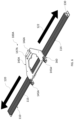
- FIG. 6 illustrates a top perspective view of another embodiment of the security apparatus for a launch monitor
- FIG. 7 illustrates a top perspective view of the embodiment of the security apparatus for a launch monitor of FIG. 6 ;
- FIG. 8 illustrates an enlarged top view of a portion of the embodiment of the security apparatus for a launch monitor of FIGS. 6 - 7 ;
- FIG. 9 illustrates the embodiment of the security apparatus for a launch monitor of FIG. 2 further including an embodiment of a protective covering installed over the launch monitor;
- FIG. 10 illustrates a bottom schematic view of an embodiment of the protective covering
- FIG. 11 illustrates the embodiment of the security apparatus for a launch monitor of FIG. 4 further including an embodiment of a protective covering installed over the launch monitor;
- FIG. 12 illustrates the embodiment of the security apparatus for a launch monitor of FIG. 5 further including an embodiment of a protective covering installed over the launch monitor.
- the security apparatus 100 for a golf launch monitor or launch monitor 200 generally includes a track or guide member 110 and a mount 140 moveably coupled to the guide member 110 using one or more guide engagers 160 , such as slide members.
- the guide member 110 extends along a guide axis T from a first end 111 to a second end 112 .
- the guide member 110 includes a top surface 114 , an opposing bottom surface 113 , and side surfaces 115 .
- the top surface 114 may define one or more top surface features 116 and the side surfaces 115 may define one or more side surface features 117 .
- the one or more top surface features 116 include a groove, a channel, and/or a ridge extending between the first end 111 and the second end 112 of the guide member 110 .
- the one or more side surfaces 115 include a groove, a channel, and/or a ridge extending along the one or more side surfaces 115 .
- the bottom surface 113 of the guided member 110 may define one or more bottom surface features (not shown).
- the guide member 110 may be secured to an anchoring fixture (such as a wall, a floor, a display fixture) using one or more brackets 130 .
- the mount 140 includes a body 142 that extends along a mount plane M (see FIG. 11 ) with a top body surface 141 having a plurality of securing members, such as clamp members 144 , 146 , and a bottom body surface 143 (see FIG. 11 ).
- the mount plane M intersects a vertical axis V at an angle ⁇ (see FIG. 8 ).
- the body 142 is generally planar, however the geometric characteristics of the body 142 and the number of clamp members 144 , 146 present may vary depending on the shape of the launch monitor 200 and/or the guide member 110 and/or characteristics of the monitoring area where the security apparatus 100 is installed.
- the securing members include two (2) forward clamp members 144 and one (1) rear clamp member 146 .
- the rear clamp member 146 includes a retainer 147 and a coupling element 149 that couples the rear clamp member 146 to the mount 140 .
- the forward clamp members 144 include a retainer 145 and a coupling element 149 that couples the forward clamp members 144 to the body 142 of the mount 140 .
- the retainers 145 of the forward clamp members 144 are split retainers 145 that comprise two (2) retaining portions 145 a , 145 b .
- the coupling element 149 is a mechanical fastener such as a nut-and-bolt or screw-and-nut combination, or a threaded fastener.
- the threaded fastener may be configured to be installed and uninstalled using a proprietary tool.
- the threaded fastener is a security screw or tamper-proof screw that has a unique screw head that makes removal nearly impossible without the corresponding proprietary tool.
- the mount 140 is attached to one or more guide engagers 160 that enable the mount 140 to be installed onto the guide member 110 .
- the guide engagers 160 comprise sliders 162 that engage at least the top surface features 116 and the side surface features 117 of the guide member 110 .
- each slider 162 engages the top surface features 116 and the side surface features 117 .
- Each slider 162 couples to the mount 140 using one or more coupling elements 148 .
- These coupling elements 148 may be similar to the coupling elements 149 of the clamp members 144 , 146 .
- the coupling elements 148 enable the clamp members 144 , 146 to be moved between an unlocked state where the clamp members 144 , 146 are able to move relative to the mount 140 , and a locked state, where the clamp members 144 , 146 are inhibited from moving relative to the mount 140 .
- the mount 140 and the guide engagers 160 may be coupled through one or more welded joints.
- the mount 140 and the guide engagers 160 may be formed as a single component.
- a lock mechanism can be included which secures the mount 140 to the one or more guide engagers 160 and can be unlocked in order to decouple the mount 140 and the one or more guide engagers 160 .
- FIGS. 6 - 8 Another embodiment of the security apparatus 100 A is shown in FIGS. 6 - 8 .
- This embodiment includes a mount 140 A with a body 142 A that extends along a mount plane M (see FIG. 11 ).
- the body 142 A further includes a top body surface 141 A having a plurality of securing members, such as clamp members 144 A, 146 A, and a bottom body surface 143 A.
- the mount plane M intersects a vertical axis Vat an angle ⁇ such as shown in FIG. 11 .
- the body 142 A is generally planar, however the geometric characteristics of the body 142 A and the number of clamp members 144 A, 146 A present may vary depending on the shape of the launch monitor 200 and/or the guide member 110 and/or characteristics of the monitoring area where the security apparatus 100 A is installed.
- the mount 140 A includes a plurality of securing members. As shown, the securing members include two (2) forward clamp members 144 A and one (1) rear clamp member 146 A.
- the rear clamp member 146 A includes a retainer 147 A and at least one securing element 149 A that couples the rear clamp member 146 A to the mount 140 A.
- the forward clamp members 144 A include a retainer 145 A and at least one securing element 149 A that couples the forward clamp members 144 A to the body 142 A of the mount 140 A.
- the retainers 145 A of the forward clamp members 144 A are split retainers 145 A that comprise two (2) retaining portions 145 A 1 , 145 A 2 .
- the securing elements 149 A is a mechanical fastener such as a nut-and-bolt or screw-and-nut combination, or a threaded fastener.
- the threaded fastener may be configured to be installed and uninstalled using a proprietary tool.
- the threaded fastener is a security screw or tamper-proof screw that has a unique screw head that makes removal nearly impossible without the corresponding proprietary tool.
- the mount 140 A is similarly attached to one or more guide engagers 160 as in previously described embodiments that enable the mount 140 A to be installed onto the guide member 110 .
- the guide engagers 160 comprise sliders 162 that engage at least the top surface features 116 and the side surface features 117 of the guide member 110 .
- each slider 162 engages the top surface features 116 and the side surface features 117 to enable the mount 140 A to move in a first direction 120 relative to the guide member 110 , and a second, opposing 122 relative to the guide member 110 .
- Each slider 162 couples to the mount 140 A using one or more coupling elements 148 . These coupling elements 148 may be similar to the securing elements 149 A of the clamp members 144 A, 146 A.
- the securing elements 149 A enable the clamp members 144 A, 146 A to be moved between an unlocked state where the clamp members 144 A, 146 A are able to move relative to the mount body 142 A, and a locked state, where the clamp members 144 A, 146 A are inhibited from moving relative to the mount body 142 A.
- the mount 140 and the guide engagers 160 may be coupled through one or more welded joints.
- the mount 140 and the guide engagers 160 may be formed as a single component.
- a lock mechanism can be included which secures the mount 140 A to the one or more guide engagers 160 and can be unlocked in order to decouple the mount 140 A and the one or more guide engagers 160 .
- a launch monitor 200 is shown as being installed or secured by the security apparatus 100 FIGS. 2 - 5 .
- the embodiment of the launch monitor 200 shown generally includes a housing 202 having a top surface 203 , a bottom surface 204 , a front facing surface 206 , a rearward facing surface 208 , and side surfaces 207 , 209 .
- the housing 202 as shown further includes two (2) legs 210 extending from the bottom housing surface 204 along a housing axis H.
- a leg base 212 is provided that has a greater diameter than the leg 210 .
- a rear support 220 extends from the bottom housing surface 204 along a rear support axis R that intersects the housing axis H.
- the launch monitor 200 Installation of the launch monitor 200 will now be described with reference to the embodiment of the security apparatus 100 shown in FIGS. 1 A- 5 , however many aspects, if not all aspects, of this installation are the same for the embodiment of the security apparatus 100 A shown in FIGS. 6 - 8 .
- the coupling elements 149 of the forward and rear clamp members 144 , 146 are loosened such that the retainers 145 , 147 may be lifted and/or otherwise moved with respect to the body 142 .
- the rear support 220 may be slid under the retainer 147 of the rear clamp member 146 .
- the retainers 145 of the forward clamp members 144 may be lifted up relative to the body 142 to enable the legs 210 of the launch monitor 200 to be positioned under the retainers 145 .
- These retainers are split retainers 145 as previously mentioned such that the retaining portions 145 a , 145 b at least partially surround the leg 210 and act to contact and retain the leg base 212 on the body 142 of the mount 140 .
- the coupling elements 149 are then tightened to secure the forward clamp members 144 and the rear clamp member 146 onto the legs 210 and rear support 220 , respectively.
- the launch monitor 200 is now secured to the mount 140 of the security apparatus 100 , which is in turn movably secured to the guide member 110 of the security apparatus 100 via the guide engagers 160 .
- the launch monitor 200 When the launch monitor 200 is secured to the mount 140 , which is moveably secured to the guide member 110 , the launch monitor 200 is capable of moving or sliding relative to the guide member 110 along the guide member axis T.
- the guide member 110 is secured to a fixture (not shown) or the ground by the brackets 130 , which prevent the sliders 160 from sliding off either the first or second end 111 , 112 of the guide member 110 . Since the guide member 110 is fixedly secured by the brackets 130 , the launch monitor 200 is protected against theft while being able to be positioned relative to a golfer in order to obtain data pertaining to the golfer's swing and transmit the data to a remote processor for further analysis.
- the front surface 206 extends along the housing axis H, which is positioned at an angle ⁇ relative to the vertical plane V so that the launch monitor 200 is properly oriented relative to the vertical plane V to monitor and obtain data from the golfer.
- the guide engagers further include a pivot member that enables the mount 140 to be pivoted relative to the guide member 110 in order to move the housing axis H relative to the vertical plane V.
- the body 142 of the mount 140 may be pivoted relative the vertical axis V so as to change the value of the angle ⁇ at which the mount plane M intersects the vertical axis V.
- the guide engagers 160 may surround the track and engage one or more bottom surface features (not shown). In another embodiment, the guide engagers 160 may be configured to be removed from the track 110 without detaching the bracket(s) 130 from the fixture (not shown) or the ground. In an embodiment, the mount 140 is configured for a snap-fit engagement with the one or more guide engagers 160 and further configured to be removed from the one or more guide engagers 160 without the use of tools. In another embodiment, one of the brackets 130 may be configured to be unlocked in order to enable removal of the one or more guide engagers 160 from an end of the track 110 without decoupling the track 110 from the fixture (not shown) or the ground.
- the forward and rear clamp members 144 A, 146 A have retainers 145 A, 147 A that are configured to enable the launch monitor 200 to be adjusted vertically while being secured by the security apparatus 100 A.
- the retainers 145 A, 147 A and retaining portions 145 A 1 , 145 A 2 are dimensioned to enable some flexibility in adjusting the launch monitor 200 while still being secured by the security apparatus 100 A.
- the security apparatus 100 may further comprise a covering 180 or sleeve that fits over the launch monitor 200 when it is being retained or secured by the security apparatus 100 .
- the covering 180 is generally formed from a plurality of sides and define an interior space 189 that is dimensioned to accommodate the launch monitor 200 .
- the covering 180 includes a top cover surface 182 , a bottom cover surface 183 , a front cover surface 184 , a rear cover surface 186 , and opposing side cover surfaces 188 .
- the bottom cover surface 183 may define an opening or passage 187 into the interior space 189 .
- the covering 180 is dimensioned to be slid over the launch monitor 200 while the launch monitor 200 is secured by the security apparatus 100 , or when the launch monitor 200 is detached from the security apparatus 100 .
- the covering 180 may engage the launch monitor and/or a part of the security apparatus 100 via a snap-fit between complimentary surfaces or surface features on the covering 180 and the part of the launch monitor 200 and/or the security apparatus 100 .
- the front cover surface 184 of the covering 180 has a length L 1 that is greater than the length L 2 of the rear cover surface 186 .
- the front surface 184 of the covering 180 is also positioned at an angle ⁇ relative to the vertical plane V.
- the rear cover surface 186 as shown in FIG.
- the covering 9 may define one or more openings or cut-outs 181 to accommodate one or more features of the security apparatus 100 and/or the launch monitor 200 .
- the one or more cut-outs may correspond to power and/or data connections to the launch monitor 200 .
- the covering may be comprised of a poly carbonate material that protects the launch monitor from kicking or strikes from a golf ball or golf club.
- the embodiments of the covering 180 depicted in FIGS. 9 , 11 , and 12 show the launch monitor 200 in phantom for the purposes of illustrating the fit of the covering 180 and does not necessarily imply that the covering 180 is transparent or translucent.
- the covering 180 may include fewer or more sides and fewer or more openings or cut-outs in order to accommodate different launch monitors.
- the covering 180 cooperates with a locking device in order to lock the covering 180 onto the security apparatus 100 and/or launch monitor 200 .
- the locking device may require a mechanical input, such as a key, to move the locking device between a locked and an unlocked state.
- the locking device may require a biometric input to move the locking device between a locked and an unlocked state.
- One or more components of the security apparatus 100 and the protective covering 180 may be colored (e.g., Safety Yellow) so that they stand out and may be comprised of a metal, such as one or more forms of steel, aluminum, zinc, or a rigid plastic or polycarbonate material.
- a metal such as one or more forms of steel, aluminum, zinc, or a rigid plastic or polycarbonate material.
Landscapes
- Engineering & Computer Science (AREA)
- General Engineering & Computer Science (AREA)
- Mechanical Engineering (AREA)
- Burglar Alarm Systems (AREA)
Abstract
Description
Claims (14)
Priority Applications (1)
| Application Number | Priority Date | Filing Date | Title |
|---|---|---|---|
| US17/554,535 US11754221B2 (en) | 2020-12-17 | 2021-12-17 | Security apparatus for a golf launch monitor |
Applications Claiming Priority (2)
| Application Number | Priority Date | Filing Date | Title |
|---|---|---|---|
| US202063126845P | 2020-12-17 | 2020-12-17 | |
| US17/554,535 US11754221B2 (en) | 2020-12-17 | 2021-12-17 | Security apparatus for a golf launch monitor |
Publications (2)
| Publication Number | Publication Date |
|---|---|
| US20220196204A1 US20220196204A1 (en) | 2022-06-23 |
| US11754221B2 true US11754221B2 (en) | 2023-09-12 |
Family
ID=82022311
Family Applications (1)
| Application Number | Title | Priority Date | Filing Date |
|---|---|---|---|
| US17/554,535 Active US11754221B2 (en) | 2020-12-17 | 2021-12-17 | Security apparatus for a golf launch monitor |
Country Status (1)
| Country | Link |
|---|---|
| US (1) | US11754221B2 (en) |
Citations (6)
| Publication number | Priority date | Publication date | Assignee | Title |
|---|---|---|---|---|
| US1011707A (en) * | 1911-02-17 | 1911-12-12 | Arthur W Ankeny | Adjustable work-support. |
| US1590726A (en) * | 1921-07-18 | 1926-06-29 | Corsgren Bernhard | Adjustable supporting device |
| US1685041A (en) * | 1926-02-04 | 1928-09-18 | Binkele Herman Christian | Copyholder |
| US20050041966A1 (en) * | 2003-08-20 | 2005-02-24 | Johnson Joseph M. | Quick-release clamp for photographic equipment |
| US9949561B2 (en) * | 2015-03-17 | 2018-04-24 | Ergotron, Inc. | Stand with magnetic retention for portable devices |
| US20190376639A1 (en) * | 2018-06-11 | 2019-12-12 | Innovative Office Products, Llc | Height-adjustable display support |
-
2021
- 2021-12-17 US US17/554,535 patent/US11754221B2/en active Active
Patent Citations (6)
| Publication number | Priority date | Publication date | Assignee | Title |
|---|---|---|---|---|
| US1011707A (en) * | 1911-02-17 | 1911-12-12 | Arthur W Ankeny | Adjustable work-support. |
| US1590726A (en) * | 1921-07-18 | 1926-06-29 | Corsgren Bernhard | Adjustable supporting device |
| US1685041A (en) * | 1926-02-04 | 1928-09-18 | Binkele Herman Christian | Copyholder |
| US20050041966A1 (en) * | 2003-08-20 | 2005-02-24 | Johnson Joseph M. | Quick-release clamp for photographic equipment |
| US9949561B2 (en) * | 2015-03-17 | 2018-04-24 | Ergotron, Inc. | Stand with magnetic retention for portable devices |
| US20190376639A1 (en) * | 2018-06-11 | 2019-12-12 | Innovative Office Products, Llc | Height-adjustable display support |
Also Published As
| Publication number | Publication date |
|---|---|
| US20220196204A1 (en) | 2022-06-23 |
Similar Documents
| Publication | Publication Date | Title |
|---|---|---|
| US7156359B2 (en) | Secure mounting system for overhead mounted projector | |
| US11007951B1 (en) | Mounting assembly | |
| US7481410B2 (en) | Equipment security apparatus | |
| US9702389B2 (en) | Corner piece for mechanically interlocking frame members | |
| US10527218B2 (en) | Mechanical shock resistant motorized drive assembly | |
| US5148282A (en) | Support structure for television monitor | |
| US20040232298A1 (en) | Flat panel display mounting system | |
| KR100968455B1 (en) | Display device | |
| US7387286B2 (en) | Self-balancing adjustable flat panel mounting system | |
| AU2003257899B2 (en) | Snap-in washers and assemblies thereof | |
| US5490655A (en) | Video/data projector and monitor ceiling/wall mount | |
| US6986489B2 (en) | Configurable mount for a peripheral device | |
| US20140246468A1 (en) | Rops mount for work vehicle display interface | |
| US10534243B2 (en) | Game camera mounting system | |
| US20060022102A1 (en) | Self-balancing adjustable mounting system with friction adjustment | |
| CA2166375A1 (en) | Video monitor suspension system | |
| US8961060B2 (en) | Corner assembly | |
| JPH08506636A (en) | Locking device for sash | |
| US11754221B2 (en) | Security apparatus for a golf launch monitor | |
| US20040113029A1 (en) | Head manipulable binocular microscope support | |
| US9387351B2 (en) | Support post assembly for a safety line system | |
| US20250115074A1 (en) | System and method for displaying harvested game animals | |
| US6710325B2 (en) | Light curtain mounting system wherein housing and mounting bracket include curved surfaces | |
| US4467486A (en) | Headboard bracket | |
| WO2021243917A1 (en) | Adjustable support, terminal assembly and gate machine |
Legal Events
| Date | Code | Title | Description |
|---|---|---|---|
| FEPP | Fee payment procedure |
Free format text: ENTITY STATUS SET TO UNDISCOUNTED (ORIGINAL EVENT CODE: BIG.); ENTITY STATUS OF PATENT OWNER: SMALL ENTITY |
|
| FEPP | Fee payment procedure |
Free format text: ENTITY STATUS SET TO SMALL (ORIGINAL EVENT CODE: SMAL); ENTITY STATUS OF PATENT OWNER: SMALL ENTITY |
|
| STPP | Information on status: patent application and granting procedure in general |
Free format text: DOCKETED NEW CASE - READY FOR EXAMINATION |
|
| AS | Assignment |
Owner name: SCORPION SECURITY PRODUCTS, INC., NEW YORK Free format text: ASSIGNMENT OF ASSIGNORS INTEREST;ASSIGNORS:GULICK, FRANKLYN W, JR.;PAGE, GARY R;GULICK, GRANT WILLIAM;REEL/FRAME:059338/0179 Effective date: 20220316 |
|
| STPP | Information on status: patent application and granting procedure in general |
Free format text: NON FINAL ACTION MAILED |
|
| STPP | Information on status: patent application and granting procedure in general |
Free format text: NOTICE OF ALLOWANCE MAILED -- APPLICATION RECEIVED IN OFFICE OF PUBLICATIONS |
|
| STPP | Information on status: patent application and granting procedure in general |
Free format text: PUBLICATIONS -- ISSUE FEE PAYMENT VERIFIED |
|
| STCF | Information on status: patent grant |
Free format text: PATENTED CASE |