US11740481B2 - Polarization folded path device with complementary angle filtering - Google Patents
Polarization folded path device with complementary angle filtering Download PDFInfo
- Publication number
- US11740481B2 US11740481B2 US16/591,044 US201916591044A US11740481B2 US 11740481 B2 US11740481 B2 US 11740481B2 US 201916591044 A US201916591044 A US 201916591044A US 11740481 B2 US11740481 B2 US 11740481B2
- Authority
- US
- United States
- Prior art keywords
- display
- exit
- light
- pfp
- overfill
- Prior art date
- Legal status (The legal status is an assumption and is not a legal conclusion. Google has not performed a legal analysis and makes no representation as to the accuracy of the status listed.)
- Active, expires
Links
- 230000010287 polarization Effects 0.000 title claims abstract description 60
- 238000001914 filtration Methods 0.000 title description 6
- 230000000295 complement effect Effects 0.000 title description 2
- 210000001747 pupil Anatomy 0.000 claims abstract description 52
- 238000003384 imaging method Methods 0.000 claims abstract description 9
- 239000004973 liquid crystal related substance Substances 0.000 claims 2
- 230000005540 biological transmission Effects 0.000 abstract description 26
- 238000000034 method Methods 0.000 abstract description 13
- 238000005286 illumination Methods 0.000 description 43
- 230000003287 optical effect Effects 0.000 description 8
- 230000007704 transition Effects 0.000 description 5
- 230000008901 benefit Effects 0.000 description 2
- 230000015556 catabolic process Effects 0.000 description 2
- 238000000576 coating method Methods 0.000 description 2
- 230000001010 compromised effect Effects 0.000 description 2
- 238000006731 degradation reaction Methods 0.000 description 2
- 230000001419 dependent effect Effects 0.000 description 2
- 230000001771 impaired effect Effects 0.000 description 2
- 230000006872 improvement Effects 0.000 description 2
- 238000012986 modification Methods 0.000 description 2
- 230000004048 modification Effects 0.000 description 2
- 101100136092 Drosophila melanogaster peng gene Proteins 0.000 description 1
- 230000009471 action Effects 0.000 description 1
- 238000003491 array Methods 0.000 description 1
- 230000002238 attenuated effect Effects 0.000 description 1
- 235000009508 confectionery Nutrition 0.000 description 1
- 230000002542 deteriorative effect Effects 0.000 description 1
- 230000000694 effects Effects 0.000 description 1
- 230000004313 glare Effects 0.000 description 1
- 238000003306 harvesting Methods 0.000 description 1
- 230000028161 membrane depolarization Effects 0.000 description 1
- 238000005457 optimization Methods 0.000 description 1
- 230000001151 other effect Effects 0.000 description 1
- 230000009467 reduction Effects 0.000 description 1
- 238000002310 reflectometry Methods 0.000 description 1
- 230000035945 sensitivity Effects 0.000 description 1
- 238000007493 shaping process Methods 0.000 description 1
- 230000009466 transformation Effects 0.000 description 1
- 238000000844 transformation Methods 0.000 description 1
Images


Classifications
-
- G—PHYSICS
- G02—OPTICS
- G02B—OPTICAL ELEMENTS, SYSTEMS OR APPARATUS
- G02B27/00—Optical systems or apparatus not provided for by any of the groups G02B1/00 - G02B26/00, G02B30/00
- G02B27/28—Optical systems or apparatus not provided for by any of the groups G02B1/00 - G02B26/00, G02B30/00 for polarising
- G02B27/286—Optical systems or apparatus not provided for by any of the groups G02B1/00 - G02B26/00, G02B30/00 for polarising for controlling or changing the state of polarisation, e.g. transforming one polarisation state into another
-
- G—PHYSICS
- G02—OPTICS
- G02B—OPTICAL ELEMENTS, SYSTEMS OR APPARATUS
- G02B27/00—Optical systems or apparatus not provided for by any of the groups G02B1/00 - G02B26/00, G02B30/00
- G02B27/01—Head-up displays
- G02B27/017—Head mounted
- G02B27/0172—Head mounted characterised by optical features
-
- G—PHYSICS
- G02—OPTICS
- G02B—OPTICAL ELEMENTS, SYSTEMS OR APPARATUS
- G02B27/00—Optical systems or apparatus not provided for by any of the groups G02B1/00 - G02B26/00, G02B30/00
- G02B27/28—Optical systems or apparatus not provided for by any of the groups G02B1/00 - G02B26/00, G02B30/00 for polarising
- G02B27/283—Optical systems or apparatus not provided for by any of the groups G02B1/00 - G02B26/00, G02B30/00 for polarising used for beam splitting or combining
-
- G—PHYSICS
- G02—OPTICS
- G02B—OPTICAL ELEMENTS, SYSTEMS OR APPARATUS
- G02B27/00—Optical systems or apparatus not provided for by any of the groups G02B1/00 - G02B26/00, G02B30/00
- G02B27/30—Collimators
-
- G—PHYSICS
- G02—OPTICS
- G02B—OPTICAL ELEMENTS, SYSTEMS OR APPARATUS
- G02B3/00—Simple or compound lenses
-
- G—PHYSICS
- G02—OPTICS
- G02B—OPTICAL ELEMENTS, SYSTEMS OR APPARATUS
- G02B5/00—Optical elements other than lenses
- G02B5/20—Filters
-
- G—PHYSICS
- G02—OPTICS
- G02B—OPTICAL ELEMENTS, SYSTEMS OR APPARATUS
- G02B5/00—Optical elements other than lenses
- G02B5/30—Polarising elements
Definitions
- This invention relates to Polarization Folded Path devices (PFP). These devices are used in a variety of applications where compact collimation is needed including viewfinders, sights and head mounted displays such as virtual reality systems.
- PFP Polarization Folded Path devices
- U.S. Pat. No. 6,075,651 discloses a compact collimating apparatus to enable a compact, lightweight display system ( FIG. 1 ).
- the architecture uses a combination of polarization management components to fold a light path.
- the heart of the system is an optical cavity with a partial reflector at the input (101) and a polarization selective reflector (102) at the output.
- a quarter-wave retarder (103) is placed in the cavity such that a round trip of the cavity converts polarization state.
- a circular polarizer (104, 105) manages the polarization entering the cavity from an outside source (106) such that light is reflected on first pass and transmitted on second pass, thereby achieving the desired fold.
- the figure also shows anti-reflection coatings (107, 108); optical elements (109, 110); a clean-up polarizer (111) and an observer (112).
- PFP Polygonalization Folded Path
- US Application 2018/0039052 describes a Head Mounted Display system using a Polarization Folded Path architecture to enable compact collimation.
- a polarization folded path device with matching illumination optics that includes an illumination system with associated light management optics (illumination), a polarization folded path cavity and an exit pupil.
- the illumination is arranged, in concert with the polarization films and partial reflectors, to optimize system transmission and contrast.
- the system includes an illumination source that either alone, or with other elements, produces circularly polarized light with a particular spatio-angular distribution.
- the angular distribution of the light which may be spatially uniform OR spatially variant, is such that light entering the PFP cavity substantially follows the intended folded path.
- a second embodiment further constrains the angular distribution such that light entering the PFP cavity, substantially follows the intended folded path AND leaves the PFP cavity through the exit pupil.
- the illumination system may be emissive, frontlit or backlit.
- the illumination system is shaped to create the required spatio-angular distribution without need for angle filtering.
- an imaging system that includes a display; a Polarization Folded Path lens with associated signal path; and an exit pupil.
- the ray bundles in the PFP lens substantially follow the signal path.
- the light entering the PFP lens may substantially leave via the Exit Pupil.
- the Exit Pupil area may be smaller than the area of the Display that is intended to be imaged.
- the display may be backlit.
- the display may be frontlit.
- the display may be an LCD, an OLED, or a MicroLED.
- Illumination of the display may be controlled to manage the angular distribution of light leaving the display.
- Light leaving the display may be substantially collected into the PFP lens. More than 3% of light leaving the display may follow the signal path through the PFP lens and leave via the Exit Pupil.
- Light entering the PFP cavity may be restricted to a 30° cone.
- an imaging system that includes a display; a Polarization Folded Path lens with associated signal path; an exit pupil; and a Polarization Based Angle Filter placed between the display and the PFP lens.
- an imaging system that includes a display; a light management system that modifies the angular distribution of the display; a Polarization Folded Path lens with associated signal path; and an exit pupil.
- the ray bundles leaving the light management system are substantially collected by the PFP lens.
- the ray bundles in the PFP lens substantially follow the signal path.
- the light entering the PFP lens may substantially leave via the Exit Pupil.
- the Exit Pupil area may be smaller than the Display area.
- the display may be backlit.
- the display may be frontlit.
- the display may be an LCD, an OLED, or a MicroLED.
- FIG. 1 Is a prior art schematic view of a Polarization Folded Path (PFP) system.
- PFP Polarization Folded Path
- FIG. 2 Shows the signal path, signal bundle and polarization sensitive area.
- FIG. 3 Shows the signal bundle, exit overfill bundle and input overfill bundle.
- FIG. 4 Shows the signal path and some non-signal paths through the system.
- FIG. 5 Is a schematic view of an inventive Polarization Folded Path Device with Complementary Angle Filtering.
- FIG. 6 Is a schematic view of backlit, frontlit and emissive embodiments.
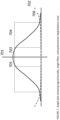
- FIG. 7 Is a representative plot showing the image bundle, angle filter region and polarization degradation region.
- the image is provided by a display that is either frontlit, backlit or self-emissive. Illumination of the display can be as much as 25% of the system power budget. As such, illumination efficiency (photons reaching user/photons generated) is an important consideration for system efficiency and battery life.
- PFP systems Another aspect of PFP systems is that the “fold” is accomplished using polarization management films and reflective surfaces, both of which have strong angular dependency. As such, the system transmission and contrast depend on the range of angles over which the polarization management components operate.
- a Polarization Folded Path device is desired, with an illumination system that is matched, in angle space, to the high-performance area of the polarization management films and the high transmission area of the folded path cavity.
- FIG. 2 shows the PFP system of FIG. 1 , further breaking down the observer ( FIG. 1 , 112 ) into three elements: pupil ( 112 a ), lens ( 112 b ) and detector ( 112 c ).
- the lens gathers light from the pupil and creates an image on the detector in the usual manner.
- FIG. 2 also shows:
- FIG. 3 breaks ‘signal path light’ into three bundles:
- the illumination system directs light into these three bundles and whether the polarization management films can ensure that light in the signal bundle leaves through the Exit Pupil as intended and light in the Exit Overfill bundle remains on the signal path so that it is effectively apertured at the Exit Pupil as intended.
- the illumination system is an LCD display with a Lambertian distribution (a commonly available and cost effective micro display)
- the cavity is designed to work with a normal incidence ⁇ 10° ray bundle (the sweet spot for many polarization management films) and the angle subtended by the cavity's input face to the display is 120° (for compactness reasons).
- the system is telecentric and the exit pupil is sized so that the entire display can be imaged.
- T system T ideal ⁇ P signal /P ilum
- the transmission efficiency issue comes from the fact that low cost, widely available Lambertian displays are a mismatch to the PFP cavity's angular constraints which are driven by the need to manage polarization over wavelength and angle using polarization management films. These films work best in a small ray bundle near Normal Incidence.
- Optimizing Transmission Efficiency requires optimizing the match between light leaving the display and light collected into the PFP Exit Pupil, namely, minimizing the Input Overfill and Exit Overfill bundles.
- Using a conventional Lambertian illumination system may consume as much as 25% of the overall system's power budget.
- less than 0.5% of the generated light reaches the user.
- the displays disclosed herein can improve this from less than 0.5% to circa 10% which would allow for an approximate 20 ⁇ reduction in the power required by the backlight.
- the Input Overfill bundle ( 302 ) does not enter the PFP cavity and so cannot travel to the Exit Pupil.
- the Exit Overfill bundle enters the cavity but will be aperture at the Exit Pupil IF the rays follow the intended signal path.
- optimizing the illumination system for image quality is equivalent to optimizing to ensure that rays entering the PFP cavity substantially follow the signal path.
- FIG. 4 shows the signal path ( 202 ) and several non-signal paths ( 401 , 402 ).
- RT n where RT refers to Round Trip and n refers to the number of trips made in the cavity.
- RT 1 is the signal path with its single fold ( 202 ).
- RT 0 is a path straight through the cavity without any fold ( 401 ) and RT 2 is a path with two Round Trips in the cavity ( 402 ).
- FIG. 4 is not exhaustive as many other non-signal paths may arise from Fresnel reflections, scatter and other sources.
- a PFP cavity is more sensitive to illumination than a conventional lens.
- signal light propagates from input to exit without recirculation and without strong polarization dependence.
- Straight through propagation simplifies baffling and controlling ray bundles that reach the exit pupil.
- non-signal paths are largely due to Fresnel reflections which can be managed to less than 0.5% using conventional anti-reflection coatings.
- RT 0 is the strongest of the non-signal paths and, due to its corrupting effects, in certain designs it may represent a limit to the practical angular extent of the signal bundle
- the RT 0 path requires specific attention as it is not attenuated by the 50/50 reflector and it does not see the optical power of the PFP cavity. For these reasons, it can lead to a strong ghost image that lies substantially inboard of the intended image and is clear, though out of focus. Though different systems have different contrast and image quality specifications, the tolerable brightness of this RT 0 ghost can be a guideline for the matching requirement of the illumination system to the PFP cavity in order to achieve image quality goals.
- US Patent Application Pub. No. 2018/0101020 discloses an arrangement where the axis of the first and second quarter-wave retarders are orthogonal to each other (Crossed). This arrangement has the advantage of presenting Linear Polarization to the Reflective Polarizer and thereby reducing the impact of the RT 0 non-signal path BUT only for near Normal Incidence rays.
- the RT 0 path strength depends on the design of the polarization management stacks. Leading to a sequence where the Exit pupil is sized, the stacks are designed, the tolerable RT 0 is assessed and the illumination is designed to ensure light entering the PFP cavity allows the RT 0 requirement to be met. The prior art is silent on these details.
- the above term “largely presents the PFP cavity with light that follows the signal path” can be interpreted in terms of the system requirements. Many systems require a contrast of above 50:1 and this requirement is continually increasing. In the PFP system, the angular dependence of the Polarization Management stacks means that the contrast depends on the azimuth and polar angle (as described in 2019/0271853). In this case, we can consider a worst case angle set, and ensure that it continues to meet the contrast and RT 0 requirement.
- Our novel techniques provide a PFP device with matching illumination to improve transmission efficiency, and image quality ( FIG. 5 ).
- Existing illumination and beam shaping techniques can be used.
- the key consideration is to design the illumination system in concert with the performance requirements of the PFP cavity to avoid transmission and image quality penalties.
- the signal bundle and the associated illumination may be spatially uniform or variant; angularly symmetric or asymmetric; and arranged around the normal or oblique.
- an angle filter ( 501 ) manages the illumination such that substantially only the signal bundle enters the cavity.
- the angle filter can be spatially uniform.
- Co-pending U.S. Application 62/745,060 “Polarization Based Filters with Angle-Sensitive Transmission” describes methods for angle filtering that is compatible with the requirements of imaging. Furthermore, light leaving these Polarization Based Angle Filters is linearly polarized and so is appropriate for feeding an AQWP to create Circularly Polarized light as required by the PFP cavity.
- the angle filter is a Polarization Based Angle Filter as disclosed in 62/745,060.
- a backlit micro-display is used and the desired illumination pattern is achieved in the backlight using a variety of techniques known in the art including, but not limited to, waveguides, light distribution films, and micro-collimators.
- the backlight unit ( 611 ) feeds the angle filter ( 612 ) which in turns feeds the display ( 613 ) resulting in light leaving the display ( 614 ) substantially in the signal bundle of the PFP ( 610 ).
- a further angle filter can be added after the display as needed.
- a reflective micro-display is front lit and the desired illumination pattern is achieved using techniques known in the art including, but not limited to, light pipes, relays lenses and flyseye systems.
- a light source ( 621 ) feeds an angle filter ( 622 ) which in turn feeds the display ( 623 ) again resulting in light leaving the display ( 624 ) substantially in the signal bundle of the PFP ( 620 ).
- the micro-display is emissive and the desired illumination is achieved with techniques known in the art such as micro-cavities, micro-lenses and light control films.
- Light is generated in the display ( 631 ) and fed to an angle filter ( 632 ) which in turn feeds the PFP.
- the angle filter is designed such that light entering the PFP is substantially in the signal bundle of the PFP.
- FIG. 7 shows a representative angle plot of ray bundles passing through the PFP cavity. At the center is normal incidence through the quarter wave retarders ( 701 ). As the angle moves from normal incidence the performance of the polarization management components deteriorates ( 702 ) until, in the compromised region ( 706 ), these components no longer allow the system to meet its image quality objectives.
- the signal bundle ( 703 ) is placed near normal incidence to allow the signal to harvest the ‘best performing rays’ from a polarization management perspective.
- the polarization management components operate well enough to keep these rays on the signal path. As such, they are extinguished at the Exit pupil. Rays in this region represent a transmission efficiency penalty but do not impact image quality.
- the compromised region ( 706 ) the polarization management components can no longer keep the rays on the signal path and other paths (eg RT 0 , RT 2 , RT n ) come into play. In this region, the mismatched illumination is a penalty for both transmission efficiency and image quality.
- the illumination system only provides light in the signal bundle as this minimizes penalties to transmission and image quality.
- this may not be practical or even possible.
- the imaging system may be required to provide largely uniform brightness across the display which, in turn, may require largely uniform angular illumination to be collected across the display.
- delivering light into the signal bundle only would require a step filter in angle space with a sharp cutoff at the edge of the signal bundle.
- Such filters can be difficult and expensive to implement.
- a preferred approach is to design the polarization management films to provide an envelope region beyond the signal bundle where the films continue to manage polarization effectively and keep rays in the PFP cavity on the signal path.
- This provides a transition region ( 704 ) for illumination system design and avoids the need for a step cutoff filter. With such a design a soft transition ( 705 ) in the illumination system will not carry an Image Quality penalty.
- the image bundle is within ⁇ 15° around normal and the signal degradation region is beyond ⁇ 30°, leaving a 15°-30° window for the angle filter transition.
- this type of illumination transition can be achieved using a variety of techniques known in the art (light guides, light management films, microlens arrays, microcavities).
- a further design consideration is etendue matching between the illumination system and the PFP cavity.
- the viewing angle and size of the exit pupil determine the target etendue which sets a starting point for the illumination system etendue.
- the display panels are larger than the PFP exit pupil, meaning that the angular extent of the panel illumination should be correspondingly smaller than the exit pupil viewing angle. This clarifies the distinction between solving the illumination problem by designing the source and solving the problem by filtering the source.
- the etendue matching is considered upfront and the generated rays that enter the PFP cavity largely follow the signal path to the Exit Pupil with some acceptable overfill. As all rays follow the signal path, the overfill rays are extinguished at the Exit Pupil and there is minimal image quality corruption. As the etendue is matched, the amount of overfill is as needed for brightness uniformity without presenting and excessive transmission penalty.
- the illumination problem must be solved by filtering. In this way, the design can still avoid an image quality penalty but there will be an inevitable transmission penalty associated with the etendue mismatch.
Landscapes
- Physics & Mathematics (AREA)
- General Physics & Mathematics (AREA)
- Optics & Photonics (AREA)
- Polarising Elements (AREA)
- Liquid Crystal (AREA)
Abstract
Description
-
- 202 the signal path (i.e. the folded path the image is designed to take through the system),
- 203 the signal bundle (i.e. the ray bundle that follows the signal path from object to image), and
- 204 the polarization sensitive area (i.e. the area where effective polarization management is needed to put light on the signal path and keep it there).
-
- 1. Signal: Signal path rays that travel from object through pupil to image (203)
- 2. Exit overfill: Signal path rays that enter the cavity but are vignetted (e.g., at exit pupil (301))
- 3. Input overfill: Signal path rays that do not enter the cavity (302)
T ideal=ηCP1·η50·η50=0.5×0.5×0.5=0.125 where
-
- Tideal is the ideal transmission efficiency of the system (ideal components) and
- ηCPI, η50 are the efficiencies of the ideal polarizer and partial reflector respectively
T system =T ideal ·P signal /P ilum where
-
- Psignal is the optical power in the signal beam bundle and
- Pilum is the optical power in the illumination bundle
P Θ=½(1−Cos 2Θ)/P π/2 where
-
- PΘ is the optical power in a cone of subtended angle Θ and
- Pπ/2 is the optical power emitted into the hemisphere
-
- Psignal/Pillum=PΘ=½(1−Cos(20))=0.03 which gives:
- Tsystem=Tideal·Psignal/Pillum=(0.125)(0.03)≈0.003 or 0.3%
TCideal=η50=0.5 where
-
- TCideal is the ideal Transmission Efficiency of the PFP cavity and
- η50 is the efficiency of the Partial reflector (as before)
TCreal=TCideal −P signal/(P signal +P exit) where
-
- TCreal is the Transmission of the ideal cavity given Collection Efficiency constraints and
- Psignal, Pexit are the optical powers in the signal and exit overfill beams respectively
-
- Psignal/(Psignal+Pexit)=0.03/(0.75)=0.04 and so
- TCreal=0.02 or 2%
-
- polarization management films to present the reflective polarizer with linearly polarized light,
- polarization management films to rotate the polarization state for the second pass, AND
- other components to do no harm.
Claims (20)
Priority Applications (1)
| Application Number | Priority Date | Filing Date | Title |
|---|---|---|---|
| US16/591,044 US11740481B2 (en) | 2018-10-02 | 2019-10-02 | Polarization folded path device with complementary angle filtering |
Applications Claiming Priority (2)
| Application Number | Priority Date | Filing Date | Title |
|---|---|---|---|
| US201862740347P | 2018-10-02 | 2018-10-02 | |
| US16/591,044 US11740481B2 (en) | 2018-10-02 | 2019-10-02 | Polarization folded path device with complementary angle filtering |
Publications (2)
| Publication Number | Publication Date |
|---|---|
| US20200241312A1 US20200241312A1 (en) | 2020-07-30 |
| US11740481B2 true US11740481B2 (en) | 2023-08-29 |
Family
ID=70055771
Family Applications (1)
| Application Number | Title | Priority Date | Filing Date |
|---|---|---|---|
| US16/591,044 Active 2040-11-11 US11740481B2 (en) | 2018-10-02 | 2019-10-02 | Polarization folded path device with complementary angle filtering |
Country Status (2)
| Country | Link |
|---|---|
| US (1) | US11740481B2 (en) |
| WO (1) | WO2020072635A1 (en) |
Families Citing this family (7)
| Publication number | Priority date | Publication date | Assignee | Title |
|---|---|---|---|---|
| US11543669B2 (en) | 2017-03-08 | 2023-01-03 | Meta Platforms Technologies, Llc | Wide angle variable neutral density filter |
| CN111108428A (en) | 2017-07-17 | 2020-05-05 | 加里夏普创新有限责任公司 | Wide Angle Compensation for Single Axis Retarder Stacks |
| US11249355B2 (en) | 2018-01-29 | 2022-02-15 | Gary Sharp Innovations, Llc | Color switch for reduced color cross-talk |
| US11269123B2 (en) | 2018-01-29 | 2022-03-08 | Gary Sharp Innovations, Llc | Hollow triple-pass optical elements |
| WO2019169170A1 (en) | 2018-03-02 | 2019-09-06 | Sharp Gary D | Retarder stack pairs for polarization basis vector transformations |
| IL316174A (en) | 2022-04-26 | 2024-12-01 | Novartis Ag | Multispecific antibodies targeting il-13 and il-18 |
| KR20250051860A (en) * | 2023-10-10 | 2025-04-18 | 삼성디스플레이 주식회사 | Lens assembly and display device comprising lens assembly |
Citations (7)
| Publication number | Priority date | Publication date | Assignee | Title |
|---|---|---|---|---|
| US20060238867A1 (en) * | 2003-05-19 | 2006-10-26 | Nitto Denko Corporation | Optical device, light-condensing backlight system, and liquid crystal display |
| US20070273798A1 (en) * | 2006-05-26 | 2007-11-29 | Silverstein Barry D | High efficiency digital cinema projection system with increased etendue |
| US20150124302A1 (en) * | 2011-12-01 | 2015-05-07 | Seereal Technologies S.A. | Method for encoding a hologram in a light modulation device |
| US20150293272A1 (en) * | 2012-11-21 | 2015-10-15 | 3M Innovative Properties Company | Optical diffusing films and methods of making same |
| US20170068100A1 (en) * | 2015-09-03 | 2017-03-09 | 3M Innovative Properties Company | Optical system |
| US20180039052A1 (en) * | 2016-08-02 | 2018-02-08 | Apple Inc. | Optical System for Head-Mounted Display |
| US20190353943A1 (en) * | 2018-05-16 | 2019-11-21 | Sharp Kabushiki Kaisha | Liquid crystal private device |
Family Cites Families (3)
| Publication number | Priority date | Publication date | Assignee | Title |
|---|---|---|---|---|
| US5715023A (en) * | 1996-04-30 | 1998-02-03 | Kaiser Electro-Optics, Inc. | Plane parallel optical collimating device employing a cholesteric liquid crystal |
| US10095036B2 (en) * | 2016-02-04 | 2018-10-09 | Google Llc | Compact near-eye display optics |
| US10401630B2 (en) * | 2016-12-20 | 2019-09-03 | Facebook Technologies, Llc | Multifocal system with polarizing elements |
-
2019
- 2019-10-02 US US16/591,044 patent/US11740481B2/en active Active
- 2019-10-02 WO PCT/US2019/054282 patent/WO2020072635A1/en not_active Ceased
Patent Citations (7)
| Publication number | Priority date | Publication date | Assignee | Title |
|---|---|---|---|---|
| US20060238867A1 (en) * | 2003-05-19 | 2006-10-26 | Nitto Denko Corporation | Optical device, light-condensing backlight system, and liquid crystal display |
| US20070273798A1 (en) * | 2006-05-26 | 2007-11-29 | Silverstein Barry D | High efficiency digital cinema projection system with increased etendue |
| US20150124302A1 (en) * | 2011-12-01 | 2015-05-07 | Seereal Technologies S.A. | Method for encoding a hologram in a light modulation device |
| US20150293272A1 (en) * | 2012-11-21 | 2015-10-15 | 3M Innovative Properties Company | Optical diffusing films and methods of making same |
| US20170068100A1 (en) * | 2015-09-03 | 2017-03-09 | 3M Innovative Properties Company | Optical system |
| US20180039052A1 (en) * | 2016-08-02 | 2018-02-08 | Apple Inc. | Optical System for Head-Mounted Display |
| US20190353943A1 (en) * | 2018-05-16 | 2019-11-21 | Sharp Kabushiki Kaisha | Liquid crystal private device |
Also Published As
| Publication number | Publication date |
|---|---|
| US20200241312A1 (en) | 2020-07-30 |
| WO2020072635A1 (en) | 2020-04-09 |
Similar Documents
| Publication | Publication Date | Title |
|---|---|---|
| US11740481B2 (en) | Polarization folded path device with complementary angle filtering | |
| US12181687B2 (en) | Optical devices and systems with dichroic beamsplitter color combiner | |
| JP7529299B2 (en) | LCOS illumination via LOE | |
| CN208953803U (en) | Optical system with compact collimated image projector | |
| JP7478800B2 (en) | Method and system for a display device having an integrated polarizer - Patents.com | |
| AU2015249417B2 (en) | Compact head-mounted display system | |
| CN101410745B (en) | Substrate-guided imaging lens | |
| US20180067315A1 (en) | Substrate-guided optical device | |
| JP2019520610A (en) | Lighting device for wearable display | |
| US9229308B2 (en) | Projection apparatus and light condensing module | |
| WO2011022231A2 (en) | Dual total internal reflection polarizing beamsplitter | |
| CN205539752U (en) | Short distance optical enlargement module and subassembly thereof | |
| EP4303641A1 (en) | Near-to-eye display optical system, optical filter and near-to-eye display device | |
| CN114942489A (en) | Optical module and head-mounted display device | |
| US20230194858A1 (en) | Optical apparatus and head-mounted device | |
| US20060274273A1 (en) | Single MEMS imager optical engine | |
| CN215116991U (en) | Augmented reality display system and augmented reality display equipment | |
| US10983317B2 (en) | Compact, lightweight optical imaging system having free-form surface and common optical axis direction | |
| WO2025044379A1 (en) | Optical module capable of eliminating stray light and near-eye display device | |
| CN217846782U (en) | Optical module and head-mounted display equipment | |
| EP1805999A1 (en) | Illumination system | |
| US20260010014A1 (en) | Display device for providing immersive image | |
| CN120848030A (en) | Head-up display device, vehicle, and method for suppressing stray light of head-up display device | |
| WO2025077389A1 (en) | Near-eye optical system and head-mounted display apparatus | |
| CN115437145A (en) | An augmented reality display system and augmented reality display device |
Legal Events
| Date | Code | Title | Description |
|---|---|---|---|
| FEPP | Fee payment procedure |
Free format text: ENTITY STATUS SET TO UNDISCOUNTED (ORIGINAL EVENT CODE: BIG.); ENTITY STATUS OF PATENT OWNER: LARGE ENTITY |
|
| FEPP | Fee payment procedure |
Free format text: ENTITY STATUS SET TO SMALL (ORIGINAL EVENT CODE: SMAL); ENTITY STATUS OF PATENT OWNER: LARGE ENTITY |
|
| STPP | Information on status: patent application and granting procedure in general |
Free format text: APPLICATION DISPATCHED FROM PREEXAM, NOT YET DOCKETED |
|
| STPP | Information on status: patent application and granting procedure in general |
Free format text: DOCKETED NEW CASE - READY FOR EXAMINATION |
|
| STPP | Information on status: patent application and granting procedure in general |
Free format text: NON FINAL ACTION MAILED |
|
| STPP | Information on status: patent application and granting procedure in general |
Free format text: RESPONSE TO NON-FINAL OFFICE ACTION ENTERED AND FORWARDED TO EXAMINER |
|
| AS | Assignment |
Owner name: GARY SHARP INNOVATIONS, INC., COLORADO Free format text: ASSIGNMENT OF ASSIGNORS INTEREST;ASSIGNORS:SHARP, GARY D;MCGETTIGAN, ANTHONY D;REEL/FRAME:059993/0167 Effective date: 20220429 |
|
| STPP | Information on status: patent application and granting procedure in general |
Free format text: FINAL REJECTION MAILED |
|
| AS | Assignment |
Owner name: META PLATFORMS TECHNOLOGIES, LLC, CALIFORNIA Free format text: SHARE PURCHASE AGREEMENT;ASSIGNOR:GARY SHARP INNOVATIONS, INC.;REEL/FRAME:061239/0452 Effective date: 20220613 |
|
| FEPP | Fee payment procedure |
Free format text: ENTITY STATUS SET TO UNDISCOUNTED (ORIGINAL EVENT CODE: BIG.); ENTITY STATUS OF PATENT OWNER: LARGE ENTITY |
|
| STPP | Information on status: patent application and granting procedure in general |
Free format text: DOCKETED NEW CASE - READY FOR EXAMINATION |
|
| STPP | Information on status: patent application and granting procedure in general |
Free format text: NON FINAL ACTION MAILED |
|
| STPP | Information on status: patent application and granting procedure in general |
Free format text: NOTICE OF ALLOWANCE MAILED -- APPLICATION RECEIVED IN OFFICE OF PUBLICATIONS |
|
| STCF | Information on status: patent grant |
Free format text: PATENTED CASE |