US11735949B2 - Sheath for convenient charging - Google Patents

Sheath for convenient charging Download PDF

Info

Publication number
US11735949B2
US11735949B2 US17/151,756 US202117151756A US11735949B2 US 11735949 B2 US11735949 B2 US 11735949B2 US 202117151756 A US202117151756 A US 202117151756A US 11735949 B2 US11735949 B2 US 11735949B2
Authority
US
United States
Prior art keywords
sheath
mobile phone
wireless charger
raised portion
opening
Prior art date
Legal status (The legal status is an assumption and is not a legal conclusion. Google has not performed a legal analysis and makes no representation as to the accuracy of the status listed.)
Active
Application number
US17/151,756
Other versions
US20210218267A1 (en
Inventor
Li Zhijian
Current Assignee (The listed assignees may be inaccurate. Google has not performed a legal analysis and makes no representation or warranty as to the accuracy of the list.)
Individual
Original Assignee
Individual
Priority date (The priority date is an assumption and is not a legal conclusion. Google has not performed a legal analysis and makes no representation as to the accuracy of the date listed.)
Filing date
Publication date
Priority claimed from CN201420692148.1U external-priority patent/CN204317802U/en
Priority claimed from CN201520737260.7U external-priority patent/CN205611975U/en
Priority claimed from US16/838,059 external-priority patent/US10931138B2/en
Application filed by Individual filed Critical Individual
Priority claimed from US17/151,741 external-priority patent/US11101683B2/en
Priority to US17/151,756 priority Critical patent/US11735949B2/en
Publication of US20210218267A1 publication Critical patent/US20210218267A1/en
Priority to US17/558,674 priority patent/US11601009B2/en
Priority to US17/903,078 priority patent/US12057733B2/en
Publication of US11735949B2 publication Critical patent/US11735949B2/en
Application granted granted Critical
Priority to US18/625,102 priority patent/US20240250553A1/en
Active legal-status Critical Current
Anticipated expiration legal-status Critical

Links

Images

Classifications

    • HELECTRICITY
    • H02GENERATION; CONVERSION OR DISTRIBUTION OF ELECTRIC POWER
    • H02JCIRCUIT ARRANGEMENTS OR SYSTEMS FOR SUPPLYING OR DISTRIBUTING ELECTRIC POWER; SYSTEMS FOR STORING ELECTRIC ENERGY
    • H02J7/00Circuit arrangements for charging or depolarising batteries or for supplying loads from batteries
    • H02J7/34Parallel operation in networks using both storage and other dc sources, e.g. providing buffering
    • H02J7/342The other DC source being a battery actively interacting with the first one, i.e. battery to battery charging
    • HELECTRICITY
    • H02GENERATION; CONVERSION OR DISTRIBUTION OF ELECTRIC POWER
    • H02JCIRCUIT ARRANGEMENTS OR SYSTEMS FOR SUPPLYING OR DISTRIBUTING ELECTRIC POWER; SYSTEMS FOR STORING ELECTRIC ENERGY
    • H02J7/00Circuit arrangements for charging or depolarising batteries or for supplying loads from batteries
    • H02J7/0042Circuit arrangements for charging or depolarising batteries or for supplying loads from batteries characterised by the mechanical construction
    • HELECTRICITY
    • H02GENERATION; CONVERSION OR DISTRIBUTION OF ELECTRIC POWER
    • H02JCIRCUIT ARRANGEMENTS OR SYSTEMS FOR SUPPLYING OR DISTRIBUTING ELECTRIC POWER; SYSTEMS FOR STORING ELECTRIC ENERGY
    • H02J7/00Circuit arrangements for charging or depolarising batteries or for supplying loads from batteries

Definitions

  • the present invention model relates to a sheath for a USB or wireless charger for convenient charging of personal devices such as smart phones, tablets or any device that requires recharging.
  • the present invention intends to overcome the disadvantages stated above, and provides a sheath that may be incorporated into luggage, bags, gloves, activewear, jacket, socks, shoes, hats, glasses, goggles, belts or anything wearable or that can be carried for convenient charging, which enables the user to charge a device or product needing to be charged conveniently at any time or any place during traveling, without necessarily opening the bag, luggage, or clothing nor taking out the power source for charging.
  • the term “body” refers to any suitable base that the sheath may be attached to for easy charging, including, without limitation a bag, luggage, clothing, activewear, shoes, hats, glasses, belt or anything wearable or that can be carried.
  • the present invention also addresses wireless charging.
  • a sheath for convenient charging comprising: a raised portion and a surrounding bottom portion, wherein the raised portion has a first closed end, a second open end and the surrounding bottom portion surrounds at least a portion of the raised portion, wherein at least a portion of the raised portion extends above an outer surface of a body, wherein the body has an inner surface, an outer surface and a fourth opening between the inner surface and the outer surface; wherein the fourth opening is between the inner surface and the outer surface, and the raised portion receives a female connector having an operative end and a cord end and a cord in communication with the cord end; wherein the operative end of the female connector is retained in the second open end of the raised portion and the cord end of the female connector is retained in the first closed end of the raised portion to provide the female connector of the UBS cable in a flat position with the operative end of the female connector being operable and above the outer surface of the body, wherein the surrounding bottom portion of the sheath is attached to a portion
  • a sheath for convenient charging comprising: a raised portion and a surrounding bottom portion, wherein the raised portion of the sheath has a first open end, a second open end and a surrounding bottom portion surrounding at least a portion of the raised portion, and at least a portion extends above an outer surface of a body, wherein the raised portion receives a female connector having an output operative end, an input operative end and a detachable cord connecting between the input operative end and a battery inside of the body, wherein the output operative end of the female connector is retained in the second open end of the raised portion and the input operative end is retained in the first open end of the sheath to provide the female connector in a flat position with the operative ends being operable and above the outer surface of the body, wherein the surrounding bottom portion is attached to a portion of the body, wherein one of the sides of the female connector has an actuation button.
  • a sheath for convenient charging having a raised portion with a fixed holder for mobile phone and a bottom portion, and at least a portion of the bottom portion communicating with a body, wherein the fixed holder for mobile phone is extends above a surface of a body, and adjustable to tightly hold different sizes, different shape of mobile phone, wherein the sheath has an opening, the rear side of raised portion receives a wireless charger, and the wireless charger stays inside of the raised portion, and can be removed from the opening of the sheath, wherein the raised portion and the fixed holder are positioned to make the wireless charger and mobile phone communicate with each other.
  • a sheath for convenient charging comprising: a raised portion with a second open end, and a bottom portion, a power storage space in the body, and a magnet component, a USB cable having a female connector with an operative end, wherein the magnet component is configured to receive a mobile phone wireless charging holder which has a magnetic adjustable component, wherein at least a portion of the bottom portion is in communication with a body, wherein, at least a portion of the sheath extends above a surface of a body, wherein the operative end of the female connector is retained in the second open end of the raised portion to provide the female connector of the UBS cable in a firm and flat position with the operative end of the female connector being operable and above the surface of the body, wherein an exit on the body is adjacent to the sheath for the cable going through, which connects the female connector in the sheath to a power storage space in the body, wherein the mobile phone wireless charger connects to the operative end of the female connector.
  • a sheath for convenient charging comprising: a raised portion with a second open end, a bottom portion, a power storage space in a body, and a universal adaptation nut, wherein the universal adaptation nut is configured to receive a mobile phone wireless charging holder, wherein at least a portion of the bottom portion is in communication with the body, wherein, at least a portion of the sheath extends above a surface of the body, wherein the operative end of a female connector is retained in the second open end of the raised portion to provide the female connector of the UBS cable in a firm and flat position with the operative end of the female connector being operable and above the surface of the body, wherein an exit on the body is adjacent to the sheath for the cable going through, which connects the female connector in the sheath to a power storage space in the body, wherein the mobile phone wireless charger connects to the operative end of the female connector.
  • a sheath for convenient charging comprising: a raised portion with a fixed adjustable mobile phone holder and a bottom portion, wherein the fixed adjustable mobile phone holder is adjustable to tightly hold different sizes, different shape of mobile phone, wherein the raised portion contains wireless charging components that are fixed inside of the sheath, wherein the sheath is on a body with a cable laying channel going from the sheath to a power storage space in the body, wherein at least a portion of the bottom portion is in communication with the body, wherein the raised portion and the fixed holder are attached to make the wireless charger and mobile phone is communication with each other, providing a stable position for a mobile phone charging by a wireless charger on the outer surface of the body.
  • a sheath for convenient charging comprising: a raised portion with a fixed holder for mobile phone and wireless charger, wherein the fixed holder is adjustable to tightly hold the both mobile phone and wireless charger in different sizes, different shapes, wherein at least a portion of the sheath is firmly attached on a body, and at least a portion of the holder extends above an outer surface of the body, wherein the raised portion with a fixed holder is attached to provide the wireless charger and the mobile phone in communication with each other, providing a stable position for a mobile phone charging by a wireless charger on the outer surface of the body.
  • a sheath for convenient charging comprising: a raised portion with a second open end, a bottom portion, a power storage space in a body, and a bracket for fixing, wherein the bracket for fixing is configured to receive a mobile phone wireless charging holder, wherein at least a portion of the bottom portion is in communication with the body, wherein, at least a portion of the sheath extends above a surface of the body, wherein the operative end of a female connector is retained in the second open end of the raised portion to provide the female connector of the UBS cable in a firm and flat position with the operative end of the female connector being operable and above the surface of the body, wherein an exit on the body is adjacent to the sheath for the cable going through, which connects the female connector in the sheath to a power storage space in the body, wherein the mobile phone wireless charger connects to the operative end of the female connector.
  • the sheath may be further equipped with a dust cap for dust proofing.
  • the sheath may also have openings for ventilation, to prevent overheating of the device.
  • the power cable outlet may be provided on the surface of the body, the female connector is operatively exposed outside the power cable outlet, and a dust cap may be attached on the side of the female connector.
  • the bag or luggage body may be provided with a cable laying channel from the power storage device placing space to the power cable outlet for the penetration of the USB extension cable.
  • the female connector of the USB extension cable may be further equipped with a Bluetooth anti-lost alarm, which is used to connect to the Bluetooth device on the product to be charged.
  • the female connector of the USB extension cable may be further equipped with a GPS device for positioning (or locating).
  • the present invention enjoys the following advantages (1) provides a body for convenient charging, which enables a user to charge a product needing to be charged conveniently at any time or any place during traveling, without necessarily opening the bag or luggage, nor taking out the power source for charging. (2) the charging interface is featured with waterproof and dust-proof functions, resulting in reliable performance; (3) the flat position of the female end of the USB provides a sturdy position for the external USB cable to connect to. In this way, a user may, with one hand attach an external USB cable; (4) the flat position of the wireless charger raised above the surface of the body provides a sturdy position for the device to be charged.
  • the sheath may also be typically installed to face down towards the ground on the body. This also provides an additional level of waterproofing, as the open end is faced downward.
  • FIGS. 1 - 2 depict an example of a bag for convenient charging according to the present invention.
  • a luggage body ( 1 ) having a placing space for placing a power storage device inside the luggage body and a power cable outlet on the outer surface of the luggage body ( 1 );
  • a USB extension cable ( 2 ) having a male connector ( 2 - 1 ) and a female connector ( 2 - 2 ) on the luggage body ( 1 ), wherein the male connector ( 2 - 1 ) of the USB extension cable is inside the luggage body ( 1 ) and is used to connect to the power storage device in the placing space;
  • the female connector ( 2 - 2 ) is in the power cable outlet or exposed outside the power cable outlet, and the female connector ( 2 - 2 ) is equipped with a sheath ( 3 ) wrapped on the outer surface of the female connector ( 2 - 2 ) for water proofing.
  • the term “luggage body” includes any bag, bag body, purse, backpack, luggage or the like.
  • the placing space would typically be a pocket on the inside of the luggage body that holds the power storage device.
  • the power storage device may be any device capable of charging a device.
  • the sheath ( 3 ) may be further equipped with a dust cap ( 4 ) for dust proofing.
  • the power cable outlet is provided on the surface of the luggage body, the female connector ( 2 - 2 ) is exposed outside the power cable outlet, and the dust cap ( 4 ) is attached on the side of the female connector ( 2 - 2 ).
  • the power cable outlet may be provided in a groove ( 5 ) on the side of the luggage body, the female connector is in the power cable outlet, and the dust cap is at the opening of the groove and connected to the groove.
  • the power cable outlet may be under the sheath ( 3 ) and therefore not viewable in FIG. 1 .
  • the luggage body may be provided with a cable laying channel from the power storage device placing space to the power cable outlet for the penetration of the USB extension cable ( 2 ).
  • the male connector of the USB extension cable is further equipped with a wireless technology standard for exchanging data over short distances (e.g.
  • BluetoothTM as an anti-loss alarm ( 9 ), which is used to connect to the device on the product to be charged.
  • the BluetoothTM on the USB extension cable would connect with the BluetoothTM on, for example, a phone and could be used to locate the luggage body.
  • the male connector of the USB extension cable may be further equipped with a GPS device ( 10 ) for positioning. The term positioning may be interchanged with locating.
  • the power cable outlet may be on a shoulder strap ( 11 ) of the bag.
  • the sheath as depicted in FIGS. 1 and 2 is a woven material or a plastic material that has at least one ventilation opening (the woven layers provide openings between each of the woven layers). The openings are small, as to protect the female connector contained inside.
  • FIG. 2 shows embodiment 2 of the utility model, which is different to the embodiment 1 that the sheath 3 is further equipped with a dust cap 4 for dust proofing, and the dust cap 4 is attached on the side of the female connector 2 - 2 , which is overturning connected to the side of the female connector 2 - 2 .
  • FIGS. 3 , 4 , 5 , 6 , 7 , 8 , 9 , 10 and 11 are intended to depict that the raised portion of the sheath may take many shapes and forms.
  • FIG. 3 depicts a curved raised portion ( 30 )
  • FIG. 4 depicts a curved raised portion ( 32 ) with a surrounding bottom portion ( 34 ).
  • FIG. 5 depicts a raised substantially rectangular shape ( 36 ) with a surrounding bottom ( 38 ) which retains the output operative end of a female connector in a second open end ( 39 ) of the sheath to provide the female connector in a flat position and protected by a first side portion ( 40 ) and second side portion ( 42 ).
  • the raised portion has a first closed end ( 41 ), a second open end ( 39 ) and the surrounding bottom portion ( 38 ) surrounds at least a portion of the raised portion
  • FIG. 5 also include an actuation button ( 37 ) in the top side of the sheath.
  • the first side portion ( 40 ) and the second side portion ( 42 ) also act to guide the output operative end of a female connector into the open end of the sheath.
  • FIG. 6 depicts an example of a dome shaped raised portion ( 44 ).
  • FIG. 7 depicts an example of a raised circular shape ( 46 ).
  • FIG. 8 depicts an example of a raised semi-circular shape ( 48 ).
  • FIGS. 9 and 11 depicts examples of raised polygon shapes (e.g. 50 and 54 ).
  • FIG. 10 depicts an example of raised square shape ( 52 ).
  • FIGS. 12 and 13 are intended to show the sheath attached to a body and two different examples of openings between the inner surface and outer surface of the body.
  • the sheath ( 60 ) has a raised portion and a surrounding bottom portion, wherein the raised portion has a first closed end, a second open end and the surrounding bottom portion surrounds at least a portion of the raised portion (see FIG. 5 for additional detail).
  • At least a portion of the raised portion extends above an outer surface of a body (in this case shoulder strap ( 62 )).
  • the body has an inner surface (inside of shoulder strap 64 ), an outer surface ( 66 ) and a fourth opening ( 68 ) between the inner surface and the outer surface. Ash shown in FIG.
  • the fourth opening is a zipper that is adjacent to the sheath to allow for adjustment or removal of the USB cable ( 70 ).
  • FIG. 13 depicts an example in which the fourth opening ( 72 ) is near or adjacent to the location of the sheath ( 76 ).
  • the sheath may be on top of and cover the fourth opening ( 72 ). This may be permanently fixed and not allow for removal of the USB cable ( 74 ).
  • the fourth opening is between the inner surface and the outer surface, and the raised portion receives a female connector having an operative end and a cord end and a cord in communication with the cord end.
  • FIGS. 14 , 15 , 16 and 17 are intended to depict an example of how the USB cable may be received in the sheath.
  • FIG. 14 , 15 , 16 and 17 are intended to depict an example of how the USB cable may be received in the sheath.
  • FIGS. 14 is a top view of a sheath with an actuation button ( 75 ) and second open end ( 77 ). Note the bottom surrounding portion in not shown in FIG. 14 .
  • FIGS. 15 and 16 depict a bottom view of a sheath with a bottom surrounding portion ( 80 ).
  • the operative end ( 76 ) of the female connector is retained in the second open end ( 82 ) of the raised portion and the cord end of the female connector is retained in the first closed end ( 100 ) of the raised portion to provide the female connector of the UBS cable in a flat position with the operative end of the female connector being operable and above the outer surface of the body.
  • the surrounding bottom portion of the sheath is attached to a portion of the body.
  • FIG. 17 and 18 are intended to depict that a portion of the body may have a fourth opening ( 92 ).
  • FIG. 17 depicts the outer surface ( 96 ) of the body and
  • FIG. 18 depicts the inner surface ( 94 ) of the body.
  • the raised portion ( 98 ) of the sheath may be a corresponding size and shape to the fourth opening.
  • the sheath has a first closed end ( 100 ), top side ( 102 ), right side ( 104 ), left side ( 106 ). In this way the surrounding bottom portion is under the outer surface of the body ( 96 ). This acts to secure the sheath with the surrounding portion not seen and provides stability. See FIG. 12 , the cord is connecting between the female connector ( 69 ) and a battery ( 65 ) inside of the body.
  • the battery ( 65 ) may be held inside a power storage space ( 67 ).
  • the cable laying channel is built on the body, from the sheath to the power storage space inside of the body.
  • the power storage space may be a pocket on the interior of a bag as shown.
  • the female connector may have an actuation button ( 75 ). If the female connector has an actuation button, there may be a third opening ( 81 ) in the sheath that is similarly shaped to allow the actuation button to be actuated and surrounds the actuation button.
  • the actuation button may actuates the function of recording and storing voice recording, photoshooting, music controlling or any other function on a phone, tablet or other device. See FIG.
  • the actuation button ( 8901 ) may be on a mainboard ( 8801 ), and further equipped with a wireless technology standard for exchanging data over short distances as an anti-loss alarm, which is used to connect to the device nearby to be charged.
  • a corresponding side of the sheath has at least one corresponding button communicating with the top of the actuation button, which connects to the mainboard of the female connector.
  • the mainboard in the female connector has a Bluetooth actuator for connecting and controlling a device nearby to be charged.
  • the mainboard may further comprises a memory card ( 8902 ). There may be a GPS device for positioning contained in the female connector.
  • FIG. 19 depicts two options of the location of the cord.
  • the cord ( 110 ) may remain under the inner surface of the body (under the surrounding bottom portion) and stay in the cable laying channel.
  • the cord ( 112 ) may be on top of the outer surface of the body (above the surrounding bottom portion).
  • FIGS. 20 and 21 depict the sheath ( 114 ) with a third opening ( 116 ) that may receive a female connector/USB interface connector ( 118 ) that sits inside the third opening ( 116 ).
  • FIGS. 24 , 25 , 26 , 27 , 28 and 29 depict the female connector/USB interface convertor.
  • FIG. 24 is a lower view
  • FIG. 25 is a top view
  • FIG. 26 is an upper view
  • FIG. 27 is a perspective view
  • FIG. 28 is a side view
  • FIG. 29 is a bottom view.
  • FIGS. 30 , 31 , 32 , 33 and 34 depict the female connector/USB interface convertor with input and output cables.
  • A is used to designate the input operative end ( 158 ) a detachable cable.
  • B is the female operative end/output operative end ( 156 ).
  • FIG. 35 depicts the body is provided with a cable laying channel ( 160 ) from a power storage device placing space to the opening between the inner surface and the outer surface of the body for penetration of the USB extension cable.
  • the fourth opening ( 162 ) is on the body adjacent to the sheath to remove and place the wireless charger inside of the sheath. This embodiment also the fourth opening ( 162 ) at the end of the cable laying channel ( 160 ) to keep the cord end ( 164 ) outside of the channel.
  • the raised portion of the sheath has a first open end ( 166 ), a second open end ( 172 ) and a surrounding bottom portion surrounding at least a portion of the raised portion, and at least a portion extends above an outer surface of a body.
  • the raised portion receives a female connector having an output operative end, an input operative end and a detachable cord connecting between the input operative end and a battery inside of the body.
  • the output operative end of the female connector is retained in the second open end ( 172 ) of the raised portion and the input operative end is retained in the first open end ( 166 ) of the sheath to provide the female connector in a flat position with the operative ends being operable and above the outer surface of the body, wherein the surrounding bottom portion is attached to a portion of the body, wherein one of the sides of the female connector has an actuation button.
  • the third opening ( 168 ) surrounds the actuation button ( 170 ).
  • the body is provided with a cable laying channel ( 160 ) from a power storage device ( 163 ) placing space to a fourth opening ( 162 ) adjacent to the sheath and leaving the cord end ( 164 ) outside of the cable laying channel ( 160 ).
  • FIG. 36 depicts a sheath with a first open end ( 180 ), third opening ( 182 ), actuation button ( 184 ) and output operative end ( 186 ).
  • FIG. 36 depicts that the substantially rectangular raised portion may have a slight curve. This is particularly useful for shoulder straps the contour comfortably to the shoulders and chest of the user.
  • FIG. 37 depicts the body is provided with a cable laying channel ( 200 ) from a power storage device placing space to a fourth opening ( 202 ) adjacent to the sheath ( 204 ) having a left side ( 214 ), right side ( 212 ), top side ( 216 ), outer surface of a body ( 222 ), third opening ( 220 ), actuation button ( 218 ) and leaving the cord end ( 206 ) outside of the cable laying channel ( 200 ).
  • the cord end ( 206 ) may detachably connected to the input operative end ( 208 ) of the female connector which is opposite the output operative end ( 210 ).
  • FIGS. 39 and 40 depict that the inside surface of the sheath further comprises at least one limit point ( 260 ) to maintain the female connector to stay tightly in place.
  • the limit point also prevents the USB cable from being pulled or dislodged during use.
  • FIGS. 41 , 42 , 43 , 44 , 45 , 46 , 47 and 48 depict difference examples of a body. This is by limitation only and intended to depict that the sheath is intended to be attached to many different types of body that can be worn or carried by a user.
  • FIG. 41 depicts a sheath ( 3500 ) on gloves ( 3502 ).
  • FIG. 42 depicts a sheath ( 3600 ) on a jacket ( 3602 ).
  • FIG. 43 depicts a sheath ( 3700 ) on socks ( 3702 ).
  • FIG. 44 depicts a sheath ( 3800 ) on a hat ( 3802 ).
  • FIG. 45 depicts a sheath ( 3900 ) on glasses ( 3902 ).
  • FIG. 41 depicts a sheath ( 3500 ) on gloves ( 3502 ).
  • FIG. 42 depicts a sheath ( 3600 ) on a jacket ( 3602 ).
  • FIG. 43 depicts a shea
  • FIG. 46 depicts a sheath ( 4000 ) on goggles ( 4002 ).
  • FIG. 47 depicts a sheath ( 4100 ) on sneakers ( 4102 ).
  • FIG. 48 depicts a sheath ( 4200 ) on a belt ( 4202 ).
  • the sheath as may have a bottom side with an opening ( 83 ) to allow the female connector to sit in the raised portion and the cord of the USB to go through the bottom side opening.
  • a cover may extend above a shoulder strap and holds the actuation device in a first opening that aligns with a power output port and a second opening that aligns with the actuation button and having a recessed portion.
  • the bottom side of the raised portion may have a bottom side opening to allow the female connector of the USB cable to sit in the sheath and the cord of the USB to go through the bottom side opening.
  • There may be a cover that extends above a shoulder strap and holds the actuation device in a first opening that aligns with a power output port and a second opening that aligns with the actuation button and having a recessed portion.
  • wireless charging in envisioned. This differs from the previously described embodiments in that the device to be charged is not plugged into a USB extension cord, but rather is wirelessly charged by contact with a wireless charging pad.
  • a sheath for convenient charging comprising: a raised portion with a fixed holder ( 360 ) for mobile phone and a bottom portion ( 362 ), and at least a portion of the bottom portion communicating with a body, wherein the fixed holder for mobile phone is extends above a surface of a body, and adjustable to tightly hold different sizes, different shape of mobile phone, wherein the sheath has an opening ( 364 ), the rear side ( 366 ) of raised portion receives a wireless charger ( 412 ), and the wireless charger stays inside of the raised portion, and can be removed from the opening of the sheath, wherein the raised portion and the fixed holder are positioned to make the wireless charger and mobile phone communicate with each other.
  • the rear side of raised portion receiving the wireless charger further comprises at least one adjustable limit point, to hold the wireless charger stay in place (See FIGS. 58 and 59 for limit points ( 408 )).
  • the adjustable limit points ( 408 ) hold the wireless charger ( 412 ) in opening ( 410 ).
  • FIG. 63 depicts the wireless charger on the shoulder strap ( 450 ).
  • the holder for mobile phone may have vacuum suctions ( 400 ) to hold a device to be charged (e.g. a phone, music player, etc.), an adjustable gripper ( 402 ), elastic band ( 404 ), woven strip ( 404 ), a regular pocket ( 407 ), band with fasteners ( 406 ).
  • a device to be charged e.g. a phone, music player, etc.
  • an adjustable gripper 402
  • elastic band 404
  • woven strip 404
  • a regular pocket 407
  • band with fasteners 406
  • the surface of the body may be inside of a bag pocket ( 9305 ), see FIG. 99 .
  • FIGS. 90 , 91 and 92 depicts the bottom portion of the sheath communicates with the body by an attachment means attaching the sheath to the body, wherein the attachment means is selected from the group consisting of stitching ( 9001 ), glue ( 9003 ), rivet ( 9002 ), screw ( 9002 ).
  • FIG. 55 depicts the raised portion further comprises a fifth opening ( 364 ), the wireless charger and mobile phone in wireless communication with each other.
  • FIG. 93 depicts a fourth opening ( 9301 ) is on the body adjacent to the sheath to remove and place the wireless charger inside of the sheath.
  • FIGS. 64 , 65 , and 66 depict a sheath for convenient charging, comprising: a raised portion with a second open end ( 500 ), and a bottom portion ( 502 ), a power storage space in the body, and a magnet component ( 504 ), a USB cable having a female connector with an operative end, wherein the magnet component is configured to receive a mobile phone wireless charging holder which has a magnetic adjustable component ( 504 ), wherein at least a portion of the bottom portion is in communication with a body ( 506 ), wherein, at least a portion of the sheath extends above a surface of a body, wherein the operative end of the female connector is retained in the second open end ( 500 ) of the raised portion to provide the female connector of the UBS cable in a firm and flat position with the operative end of the female connector being operable and above the surface of the body, wherein an exit on the body is adjacent to the sheath for the cable going through, which connects the female connector in the sheath to
  • the device for wireless charging may be retained by a universal adaptation nut, as depicted in FIGS. 67 and 68 , depicting a sheath for convenient charging, having a raised portion with a second open end ( 600 ), a bottom portion ( 602 ), a power storage space in a body, and a universal adaptation nut ( 604 and 606 ), wherein the universal adaptation nut is configured to receive a mobile phone wireless charging holder ( 608 ).
  • the wireless charging holder may be purchased by the user and is apart from the sheath, the universal adaption nut is configured to receive any such wireless charging holder.
  • At least a portion of the bottom portion is in communication with the body, at least a portion of the sheath extends above a surface of the body, the operative end of a female connector is retained in the second open end ( 600 ) of the raised portion to provide the female connector of the UBS cable in a firm and flat position with the operative end of the female connector being operable and above the surface of the body, an exit on the body is adjacent to the sheath for the cable ( 609 ) going through, which connects the female connector in the sheath to a power storage space in the body, the mobile phone wireless charger connects to the operative end ( 610 ) of the female connector.
  • a sheath for convenient charging comprising: a raised portion with a fixed adjustable mobile phone holder and a bottom portion, wherein the fixed adjustable mobile phone holder is adjustable to tightly hold different sizes, different shape of mobile phone, wherein the raised portion contains wireless charging components that are fixed inside of the sheath, wherein the sheath is on a body with a cable laying channel going from the sheath to a power storage space in the body, wherein at least a portion of the bottom portion is in communication with the body, wherein the raised portion and the fixed holder are attached to make the wireless charger and mobile phone is communication with each other, providing a stable position for a mobile phone charging by a wireless charger on the outer surface of the body.
  • FIGS. 75 and 76 depict a different example of an adjustable mobile phone holder.
  • the at least one connecting bar ( 632 ) may act to attach the sheath to the body.
  • the raised portion may further comprises a fifth opening ( 626 ), the wireless charger and mobile phone in communication with each other.
  • FIGS. 80 , 81 , 82 , 83 , 84 , 85 , 94 , 95 , 96 , 97 and 98 depict a sheath ( 636 ) for convenient charging, comprising: a raised portion with a fixed holder ( 638 ) for mobile phone and wireless charger, wherein the fixed holder is adjustable to tightly hold the both mobile phone and wireless charger in different sizes, different shapes, wherein at least a portion of the sheath is firmly attached on a body, and at least a portion of the holder extends above an outer surface of the body ( 640 ), wherein the raised portion with a fixed holder is attached to provide the wireless charger and the mobile phone in communication with each other, providing a stable position for a mobile phone charging by a wireless charger on the outer surface of the body.
  • an adjustable fixed holder is intended to retain a device in a position such that it can be wirelessly charged by a wireless charger that is retained inside the raised portion.
  • Retaining the phone can take many forms such as vacuum suction, adjustable gripper, elastic band, woven strip and band with fasteners.
  • the bottom portion of sheath is in communication with the body by an attachment means, wherein the attachment means is selected from the group consisting of stitching, glue, rivet and screw.
  • FIGS. 86 and 87 depict a sheath for convenient charging, comprising: a raised portion with a second open end, a bottom portion, a power storage space in a body, and a bracket ( 642 ) for fixing, wherein the bracket for fixing is configured to receive a mobile phone wireless charging holder (as shown above that bracket may be in the opening to get enough space to receive the clip on the wireless charger).
  • the wireless charger may have a clip ( 644 ) that connects to the bracket ( 642 ) to retain the device in a proximity to the wireless charger to allow for charging.
  • At least a portion of the bottom portion is in communication with the body, at least a portion of the sheath extends above a surface of the body, the operative end of a female connector is retained in the second open end of the raised portion to provide the female connector of the UBS cable in a firm and flat position with the operative end of the female connector being operable and above the surface of the body, an exit on the body is adjacent to the sheath for the cable going through, which connects the female connector in the sheath to a power storage space in the body, the mobile phone wireless charger connects to the operative end of the female connector.
  • the bottom portion of the sheath is attached to the body by stitching, glue, rivet, screw.
  • the sheath may be attached to the body with the first tapered closed end above the second open end. Specially, the second open end is substantially parallel to the ground of the user. This is to say that the open end of the sheath faces the ground. This provides another level of dust and water protection to the operative end of the USB cable.

Landscapes

  • Engineering & Computer Science (AREA)
  • Power Engineering (AREA)
  • Purses, Travelling Bags, Baskets, Or Suitcases (AREA)

Abstract

A sheath for convenient charging, comprising: a raised portion with a fixed holder for mobile phone and a bottom portion, and at least a portion of the bottom portion communicating with a body, wherein the fixed holder for mobile phone is extends above a surface of a body, and adjustable to tightly hold different sizes, different shape of mobile phone, wherein the sheath has an opening, the rear side of raised portion receives a wireless charger, and the wireless charger stays inside of the raised portion, and can be removed from the opening of the sheath, wherein the raised portion and the fixed holder are positioned to make the wireless charger and mobile phone communicate with each other.

Description

PRIORITY CLAIM
This application claims priority to and is a continuation-in-part to application Ser. No. 16/838,059 entitled, “Sheath for USB Charger” which in turn claims priority to application Ser. No. 16/388,994 filed Apr. 19, 2019 as a continuation-in-part and is a continuation of application Ser. No. 14/836,104 filed Aug. 26, 2015, the entire contents of each of which are incorporated by reference herein in their entirety. This applications claims priority to and is a continuation in part to Ser. No. 16/388,994 entitled, “Sheath for USB Charger” which in turn claims priority to application to and is a continuation of application Ser. No. 14/836,104 filed Aug. 26, 2015 and claims priority to Chinese application number 201420692148.1 filed Nov. 18, 2014, the entire contents of each of which are incorporated by reference herein in their entirety. This application claims priority to application Ser. No. 16/738,208 filed Jan. 9, 2020 which in turn claims priority to Ser. No. 16/007,055 filed Jun. 13, 2018 and application Ser. No. 14/930,719 filed Nov. 3, 2015.
TECHNICAL FIELD
The present invention model relates to a sheath for a USB or wireless charger for convenient charging of personal devices such as smart phones, tablets or any device that requires recharging.
BACKGROUND OF THE INVENTION
With the constant development of our society, diverse portable digital devices are emerging in our lives, and we rely more and more on them, including tablet computers, cellphones, digital cameras, video cameras and the like. In addition to containing the stuff, people want more functionality from the bags and luggage. For example, charging the portable digital devices. Especially for tourists, field staff and those making long-term business trips, it is not easy to charge their digital devices when the battery is dying, causing a lot of inconvenience and trouble in their works and lives. The sheath according to the present invention allows for bags, luggage, clothing, activewear and anything wearable or carried to be equipped with a charging function, or a portable power source. It is no longer necessary to open the bag, luggage or clothing for charging, which is convenient.
SUMMARY OF THE INVENTION
The present invention intends to overcome the disadvantages stated above, and provides a sheath that may be incorporated into luggage, bags, gloves, activewear, jacket, socks, shoes, hats, glasses, goggles, belts or anything wearable or that can be carried for convenient charging, which enables the user to charge a device or product needing to be charged conveniently at any time or any place during traveling, without necessarily opening the bag, luggage, or clothing nor taking out the power source for charging. The term “body” refers to any suitable base that the sheath may be attached to for easy charging, including, without limitation a bag, luggage, clothing, activewear, shoes, hats, glasses, belt or anything wearable or that can be carried. The present invention also addresses wireless charging.
According to one aspect of the present invention, a sheath for convenient charging is provided, comprising: a raised portion and a surrounding bottom portion, wherein the raised portion has a first closed end, a second open end and the surrounding bottom portion surrounds at least a portion of the raised portion, wherein at least a portion of the raised portion extends above an outer surface of a body, wherein the body has an inner surface, an outer surface and a fourth opening between the inner surface and the outer surface; wherein the fourth opening is between the inner surface and the outer surface, and the raised portion receives a female connector having an operative end and a cord end and a cord in communication with the cord end; wherein the operative end of the female connector is retained in the second open end of the raised portion and the cord end of the female connector is retained in the first closed end of the raised portion to provide the female connector of the UBS cable in a flat position with the operative end of the female connector being operable and above the outer surface of the body, wherein the surrounding bottom portion of the sheath is attached to a portion of the body, wherein the cord is connecting between the female connector and a battery inside of the body, wherein the female connector has an actuation button.
According to another aspect of the present invention, a sheath for convenient charging, comprising: a raised portion and a surrounding bottom portion, wherein the raised portion of the sheath has a first open end, a second open end and a surrounding bottom portion surrounding at least a portion of the raised portion, and at least a portion extends above an outer surface of a body, wherein the raised portion receives a female connector having an output operative end, an input operative end and a detachable cord connecting between the input operative end and a battery inside of the body, wherein the output operative end of the female connector is retained in the second open end of the raised portion and the input operative end is retained in the first open end of the sheath to provide the female connector in a flat position with the operative ends being operable and above the outer surface of the body, wherein the surrounding bottom portion is attached to a portion of the body, wherein one of the sides of the female connector has an actuation button.
According to another aspect of the present invention, a sheath for convenient charging is provided having a raised portion with a fixed holder for mobile phone and a bottom portion, and at least a portion of the bottom portion communicating with a body, wherein the fixed holder for mobile phone is extends above a surface of a body, and adjustable to tightly hold different sizes, different shape of mobile phone, wherein the sheath has an opening, the rear side of raised portion receives a wireless charger, and the wireless charger stays inside of the raised portion, and can be removed from the opening of the sheath, wherein the raised portion and the fixed holder are positioned to make the wireless charger and mobile phone communicate with each other.
According to another aspect of the present invention, a sheath for convenient charging, comprising: a raised portion with a second open end, and a bottom portion, a power storage space in the body, and a magnet component, a USB cable having a female connector with an operative end, wherein the magnet component is configured to receive a mobile phone wireless charging holder which has a magnetic adjustable component, wherein at least a portion of the bottom portion is in communication with a body, wherein, at least a portion of the sheath extends above a surface of a body, wherein the operative end of the female connector is retained in the second open end of the raised portion to provide the female connector of the UBS cable in a firm and flat position with the operative end of the female connector being operable and above the surface of the body, wherein an exit on the body is adjacent to the sheath for the cable going through, which connects the female connector in the sheath to a power storage space in the body, wherein the mobile phone wireless charger connects to the operative end of the female connector.
According to another aspect of the present invention, a sheath for convenient charging, comprising: a raised portion with a second open end, a bottom portion, a power storage space in a body, and a universal adaptation nut, wherein the universal adaptation nut is configured to receive a mobile phone wireless charging holder, wherein at least a portion of the bottom portion is in communication with the body, wherein, at least a portion of the sheath extends above a surface of the body, wherein the operative end of a female connector is retained in the second open end of the raised portion to provide the female connector of the UBS cable in a firm and flat position with the operative end of the female connector being operable and above the surface of the body, wherein an exit on the body is adjacent to the sheath for the cable going through, which connects the female connector in the sheath to a power storage space in the body, wherein the mobile phone wireless charger connects to the operative end of the female connector.
According to another aspect of the present invention, a sheath for convenient charging, comprising: a raised portion with a fixed adjustable mobile phone holder and a bottom portion, wherein the fixed adjustable mobile phone holder is adjustable to tightly hold different sizes, different shape of mobile phone, wherein the raised portion contains wireless charging components that are fixed inside of the sheath, wherein the sheath is on a body with a cable laying channel going from the sheath to a power storage space in the body, wherein at least a portion of the bottom portion is in communication with the body, wherein the raised portion and the fixed holder are attached to make the wireless charger and mobile phone is communication with each other, providing a stable position for a mobile phone charging by a wireless charger on the outer surface of the body.
According to another aspect of the present invention, a sheath for convenient charging is provided, comprising: a raised portion with a fixed holder for mobile phone and wireless charger, wherein the fixed holder is adjustable to tightly hold the both mobile phone and wireless charger in different sizes, different shapes, wherein at least a portion of the sheath is firmly attached on a body, and at least a portion of the holder extends above an outer surface of the body, wherein the raised portion with a fixed holder is attached to provide the wireless charger and the mobile phone in communication with each other, providing a stable position for a mobile phone charging by a wireless charger on the outer surface of the body.
According to another aspect of the present invention, a sheath for convenient charging, comprising: a raised portion with a second open end, a bottom portion, a power storage space in a body, and a bracket for fixing, wherein the bracket for fixing is configured to receive a mobile phone wireless charging holder, wherein at least a portion of the bottom portion is in communication with the body, wherein, at least a portion of the sheath extends above a surface of the body, wherein the operative end of a female connector is retained in the second open end of the raised portion to provide the female connector of the UBS cable in a firm and flat position with the operative end of the female connector being operable and above the surface of the body, wherein an exit on the body is adjacent to the sheath for the cable going through, which connects the female connector in the sheath to a power storage space in the body, wherein the mobile phone wireless charger connects to the operative end of the female connector.
During traveling, when the battery of the product to be charged is dying, it is only necessary to plug the charging interface of the product to be charged into the female end of the USB cable, or place the product on the wireless charger, then the charging starts, without necessarily opening the bag or luggage, nor taking out the power source for charging. And nowadays, many consumer have wireless chargers, which may be inconvenient to use when they are walking, running, climbing, etc, outside. The present invention offers a sheath which can help to hold the wireless charger, then consumers can “turn material resources to good account”.
The sheath may be further equipped with a dust cap for dust proofing. The sheath may also have openings for ventilation, to prevent overheating of the device. The power cable outlet may be provided on the surface of the body, the female connector is operatively exposed outside the power cable outlet, and a dust cap may be attached on the side of the female connector. For the convenience of the configuration of the USB extension cable, the bag or luggage body may be provided with a cable laying channel from the power storage device placing space to the power cable outlet for the penetration of the USB extension cable. In order to prevent the loss of the bag or luggage, the female connector of the USB extension cable may be further equipped with a Bluetooth anti-lost alarm, which is used to connect to the Bluetooth device on the product to be charged. For real-time positioning or location of the bag or luggage for convenient charging provided by the utility model, the female connector of the USB extension cable may be further equipped with a GPS device for positioning (or locating).
Compared with the prior art, the present invention enjoys the following advantages (1) provides a body for convenient charging, which enables a user to charge a product needing to be charged conveniently at any time or any place during traveling, without necessarily opening the bag or luggage, nor taking out the power source for charging. (2) the charging interface is featured with waterproof and dust-proof functions, resulting in reliable performance; (3) the flat position of the female end of the USB provides a sturdy position for the external USB cable to connect to. In this way, a user may, with one hand attach an external USB cable; (4) the flat position of the wireless charger raised above the surface of the body provides a sturdy position for the device to be charged. The sheath may also be typically installed to face down towards the ground on the body. This also provides an additional level of waterproofing, as the open end is faced downward.
BRIEF DESCRIPTION OF THE DRAWINGS
The utility model is further described as follows with reference to drawings and embodiments:
FIGS. 1, 2, 3, 4, 5, 6, 7, 8, 9, 10, 11, 12, 13, 14, 15, 16, 17, 18, 19, 20, 21 , 22, 23, 24, 25 26, 27, 28, 29, 30, 31, 32, 33, 34, 35, 36, 37, 38, 39, 40, 41, 42, 43, 44, 45, 46, 47, 48, 49, 50, 51, 52, 53, 54, 55, 56, 57, 58, 59, 60, 61, 62, 63, 64, 65, 66, 67, 68, 69, 70, 71, 72, 73, 74, 75, 76, 77, 78, 79, 80, 81, 82, 83, 84, 85, 86, 87, 88, 89, 90, 91, 92, 93, 94, 95, 96, 97, 98, and 99 depict aspects of the present invention.
DETAILED DESCRIPTION OF THE EMBODIMENTS
The content of the utility model is further described in detail as follows with reference to the drawings for specification and specific embodiments.
FIGS. 1-2 depict an example of a bag for convenient charging according to the present invention. As shown, there is a luggage body (1) having a placing space for placing a power storage device inside the luggage body and a power cable outlet on the outer surface of the luggage body (1); a USB extension cable (2) having a male connector (2-1) and a female connector (2-2) on the luggage body (1), wherein the male connector (2-1) of the USB extension cable is inside the luggage body (1) and is used to connect to the power storage device in the placing space; wherein the female connector (2-2) is in the power cable outlet or exposed outside the power cable outlet, and the female connector (2-2) is equipped with a sheath (3) wrapped on the outer surface of the female connector (2-2) for water proofing. The term “luggage body” includes any bag, bag body, purse, backpack, luggage or the like. The placing space would typically be a pocket on the inside of the luggage body that holds the power storage device. The power storage device may be any device capable of charging a device. The sheath (3) may be further equipped with a dust cap (4) for dust proofing. The power cable outlet is provided on the surface of the luggage body, the female connector (2-2) is exposed outside the power cable outlet, and the dust cap (4) is attached on the side of the female connector (2-2). The power cable outlet may be provided in a groove (5) on the side of the luggage body, the female connector is in the power cable outlet, and the dust cap is at the opening of the groove and connected to the groove. The power cable outlet may be under the sheath (3) and therefore not viewable in FIG. 1 . This allows the USB extension cable (2) to be on the inside of the bag or body and connect to, for example, a power bank contained on the inside of the bag or luggage body. The luggage body may be provided with a cable laying channel from the power storage device placing space to the power cable outlet for the penetration of the USB extension cable (2). The male connector of the USB extension cable is further equipped with a wireless technology standard for exchanging data over short distances (e.g. Bluetooth™) as an anti-loss alarm (9), which is used to connect to the device on the product to be charged. The Bluetooth™ on the USB extension cable would connect with the Bluetooth™ on, for example, a phone and could be used to locate the luggage body. The male connector of the USB extension cable may be further equipped with a GPS device (10) for positioning. The term positioning may be interchanged with locating. The power cable outlet may be on a shoulder strap (11) of the bag. The sheath as depicted in FIGS. 1 and 2 is a woven material or a plastic material that has at least one ventilation opening (the woven layers provide openings between each of the woven layers). The openings are small, as to protect the female connector contained inside.
During traveling, when the battery of the product to be charged is dying, it is only necessary to plug the external USB connecting line 12 to the female connector 2-2 of the USB extension cable 2, then the charging starts, without necessarily opening the bag or luggage, nor taking out the power source for charging.
FIG. 2 shows embodiment 2 of the utility model, which is different to the embodiment 1 that the sheath 3 is further equipped with a dust cap 4 for dust proofing, and the dust cap 4 is attached on the side of the female connector 2-2, which is overturning connected to the side of the female connector 2-2.
FIGS. 3, 4, 5, 6, 7, 8, 9, 10 and 11 are intended to depict that the raised portion of the sheath may take many shapes and forms. FIG. 3 , for example depicts a curved raised portion (30), FIG. 4 , depicts a curved raised portion (32) with a surrounding bottom portion (34). FIG. 5 depicts a raised substantially rectangular shape (36) with a surrounding bottom (38) which retains the output operative end of a female connector in a second open end (39) of the sheath to provide the female connector in a flat position and protected by a first side portion (40) and second side portion (42). The raised portion has a first closed end (41), a second open end (39) and the surrounding bottom portion (38) surrounds at least a portion of the raised portion FIG. 5 also include an actuation button (37) in the top side of the sheath. The first side portion (40) and the second side portion (42) also act to guide the output operative end of a female connector into the open end of the sheath. FIG. 6 depicts an example of a dome shaped raised portion (44). FIG. 7 depicts an example of a raised circular shape (46). FIG. 8 depicts an example of a raised semi-circular shape (48). FIGS. 9 and 11 depicts examples of raised polygon shapes (e.g. 50 and 54). FIG. 10 depicts an example of raised square shape (52).
FIGS. 12 and 13 are intended to show the sheath attached to a body and two different examples of openings between the inner surface and outer surface of the body. As shown, the sheath (60) has a raised portion and a surrounding bottom portion, wherein the raised portion has a first closed end, a second open end and the surrounding bottom portion surrounds at least a portion of the raised portion (see FIG. 5 for additional detail). At least a portion of the raised portion extends above an outer surface of a body (in this case shoulder strap (62)). The body has an inner surface (inside of shoulder strap 64), an outer surface (66) and a fourth opening (68) between the inner surface and the outer surface. Ash shown in FIG. 12 , the fourth opening is a zipper that is adjacent to the sheath to allow for adjustment or removal of the USB cable (70). FIG. 13 depicts an example in which the fourth opening (72) is near or adjacent to the location of the sheath (76). The sheath may be on top of and cover the fourth opening (72). This may be permanently fixed and not allow for removal of the USB cable (74). The fourth opening is between the inner surface and the outer surface, and the raised portion receives a female connector having an operative end and a cord end and a cord in communication with the cord end. FIGS. 14, 15, 16 and 17 are intended to depict an example of how the USB cable may be received in the sheath. FIG. 14 is a top view of a sheath with an actuation button (75) and second open end (77). Note the bottom surrounding portion in not shown in FIG. 14 . FIGS. 15 and 16 depict a bottom view of a sheath with a bottom surrounding portion (80). The operative end (76) of the female connector is retained in the second open end (82) of the raised portion and the cord end of the female connector is retained in the first closed end (100) of the raised portion to provide the female connector of the UBS cable in a flat position with the operative end of the female connector being operable and above the outer surface of the body. The surrounding bottom portion of the sheath is attached to a portion of the body. FIGS. 17 and 18 are intended to depict that a portion of the body may have a fourth opening (92). FIG. 17 depicts the outer surface (96) of the body and FIG. 18 depicts the inner surface (94) of the body. The raised portion (98) of the sheath may be a corresponding size and shape to the fourth opening. The sheath has a first closed end (100), top side (102), right side (104), left side (106). In this way the surrounding bottom portion is under the outer surface of the body (96). This acts to secure the sheath with the surrounding portion not seen and provides stability. See FIG. 12 , the cord is connecting between the female connector (69) and a battery (65) inside of the body. The battery (65) may be held inside a power storage space (67). The cable laying channel is built on the body, from the sheath to the power storage space inside of the body. The power storage space may be a pocket on the interior of a bag as shown. The female connector may have an actuation button (75). If the female connector has an actuation button, there may be a third opening (81) in the sheath that is similarly shaped to allow the actuation button to be actuated and surrounds the actuation button. The actuation button may actuates the function of recording and storing voice recording, photoshooting, music controlling or any other function on a phone, tablet or other device. See FIG. 88, 89 , the actuation button (8901) may be on a mainboard (8801), and further equipped with a wireless technology standard for exchanging data over short distances as an anti-loss alarm, which is used to connect to the device nearby to be charged. A corresponding side of the sheath has at least one corresponding button communicating with the top of the actuation button, which connects to the mainboard of the female connector. The mainboard in the female connector has a Bluetooth actuator for connecting and controlling a device nearby to be charged. The mainboard may further comprises a memory card (8902). There may be a GPS device for positioning contained in the female connector.
FIG. 19 depicts two options of the location of the cord. The cord (110) may remain under the inner surface of the body (under the surrounding bottom portion) and stay in the cable laying channel. Alternatively, the cord (112) may be on top of the outer surface of the body (above the surrounding bottom portion).
FIGS. 20 and 21 depict the sheath (114) with a third opening (116) that may receive a female connector/USB interface connector (118) that sits inside the third opening (116). FIGS. 22 and 23 depict one example of a sheath with a first closed end (120), a left side (122), a right side (124), a top side (126), a surrounding bottom portion (132), third opening (130), second open end (128) and actuation button (134). FIGS. 24, 25, 26, 27, 28 and 29 depict the female connector/USB interface convertor. FIG. 24 is a lower view, FIG. 25 is a top view, FIG. 26 is an upper view, FIG. 27 is a perspective view, FIG. 28 is a side view and FIG. 29 is a bottom view. There is a female operative end/USB output operative end (150), an actuation button (152) and input operative end (154).
FIGS. 30, 31, 32, 33 and 34 depict the female connector/USB interface convertor with input and output cables. A is used to designate the input operative end (158) a detachable cable. B is the female operative end/output operative end (156).
FIG. 35 depicts the body is provided with a cable laying channel (160) from a power storage device placing space to the opening between the inner surface and the outer surface of the body for penetration of the USB extension cable. The fourth opening (162) is on the body adjacent to the sheath to remove and place the wireless charger inside of the sheath. This embodiment also the fourth opening (162) at the end of the cable laying channel (160) to keep the cord end (164) outside of the channel. The raised portion of the sheath has a first open end (166), a second open end (172) and a surrounding bottom portion surrounding at least a portion of the raised portion, and at least a portion extends above an outer surface of a body. The raised portion receives a female connector having an output operative end, an input operative end and a detachable cord connecting between the input operative end and a battery inside of the body. The output operative end of the female connector is retained in the second open end (172) of the raised portion and the input operative end is retained in the first open end (166) of the sheath to provide the female connector in a flat position with the operative ends being operable and above the outer surface of the body, wherein the surrounding bottom portion is attached to a portion of the body, wherein one of the sides of the female connector has an actuation button. The third opening (168) surrounds the actuation button (170).
The body is provided with a cable laying channel (160) from a power storage device (163) placing space to a fourth opening (162) adjacent to the sheath and leaving the cord end (164) outside of the cable laying channel (160). FIG. 36 depicts a sheath with a first open end (180), third opening (182), actuation button (184) and output operative end (186). FIG. 36 depicts that the substantially rectangular raised portion may have a slight curve. This is particularly useful for shoulder straps the contour comfortably to the shoulders and chest of the user.
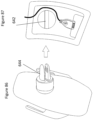
FIG. 37 depicts the body is provided with a cable laying channel (200) from a power storage device placing space to a fourth opening (202) adjacent to the sheath (204) having a left side (214), right side (212), top side (216), outer surface of a body (222), third opening (220), actuation button (218) and leaving the cord end (206) outside of the cable laying channel (200). The cord end (206) may detachably connected to the input operative end (208) of the female connector which is opposite the output operative end (210). FIG. 38 depicts the female connector (230), input operative end (232), cord end (234), cord (236), actuation button (238), second open end (240), surrounding bottom portion (242), first open end (244), top side (246), right side (248), left side (250), third opening (252) and outer surface of body (254).
FIGS. 39 and 40 depict that the inside surface of the sheath further comprises at least one limit point (260) to maintain the female connector to stay tightly in place. The limit point also prevents the USB cable from being pulled or dislodged during use.
FIGS. 41, 42, 43, 44, 45, 46, 47 and 48 depict difference examples of a body. This is by limitation only and intended to depict that the sheath is intended to be attached to many different types of body that can be worn or carried by a user. FIG. 41 depicts a sheath (3500) on gloves (3502). FIG. 42 depicts a sheath (3600) on a jacket (3602). FIG. 43 depicts a sheath (3700) on socks (3702). FIG. 44 depicts a sheath (3800) on a hat (3802). FIG. 45 depicts a sheath (3900) on glasses (3902). FIG. 46 depicts a sheath (4000) on goggles (4002). FIG. 47 depicts a sheath (4100) on sneakers (4102). FIG. 48 depicts a sheath (4200) on a belt (4202). The sheath as may have a bottom side with an opening (83) to allow the female connector to sit in the raised portion and the cord of the USB to go through the bottom side opening. A cover may extend above a shoulder strap and holds the actuation device in a first opening that aligns with a power output port and a second opening that aligns with the actuation button and having a recessed portion. The bottom side of the raised portion may have a bottom side opening to allow the female connector of the USB cable to sit in the sheath and the cord of the USB to go through the bottom side opening. There may be a cover that extends above a shoulder strap and holds the actuation device in a first opening that aligns with a power output port and a second opening that aligns with the actuation button and having a recessed portion.
According to another aspect of the present invention, wireless charging in envisioned. This differs from the previously described embodiments in that the device to be charged is not plugged into a USB extension cord, but rather is wirelessly charged by contact with a wireless charging pad. FIGS. 49, 50, 51, 52, 53, 54, 55, 56, 57, 58, 59, 60, 61, 62, 63, 64, 65, 66, 67, 68, 69 , 70, 71, 72, 73, 74, 75, 76, 77, 78, 79, 80, 81, 82, 83, 84, 85, 86, 87, 90, 91, 92, 93, 94, 95, 96, 97, 98, and 99 depict wireless charging embodiments according to the present invention.
A sheath for convenient charging, comprising: a raised portion with a fixed holder (360) for mobile phone and a bottom portion (362), and at least a portion of the bottom portion communicating with a body, wherein the fixed holder for mobile phone is extends above a surface of a body, and adjustable to tightly hold different sizes, different shape of mobile phone, wherein the sheath has an opening (364), the rear side (366) of raised portion receives a wireless charger (412), and the wireless charger stays inside of the raised portion, and can be removed from the opening of the sheath, wherein the raised portion and the fixed holder are positioned to make the wireless charger and mobile phone communicate with each other. This provides a stable position for a mobile phone or other device to charge wirelessly on the outer surface of the body. The rear side of raised portion receiving the wireless charger further comprises at least one adjustable limit point, to hold the wireless charger stay in place (See FIGS. 58 and 59 for limit points (408)). The adjustable limit points (408) hold the wireless charger (412) in opening (410). FIG. 63 depicts the wireless charger on the shoulder strap (450).
The holder for mobile phone may have vacuum suctions (400) to hold a device to be charged (e.g. a phone, music player, etc.), an adjustable gripper (402), elastic band (404), woven strip (404), a regular pocket (407), band with fasteners (406). The surface of the body may be inside of a bag pocket (9305), see FIG. 99 .
FIGS. 90, 91 and 92 depicts the bottom portion of the sheath communicates with the body by an attachment means attaching the sheath to the body, wherein the attachment means is selected from the group consisting of stitching (9001), glue (9003), rivet (9002), screw (9002).
FIG. 55 depicts the raised portion further comprises a fifth opening (364), the wireless charger and mobile phone in wireless communication with each other. FIG. 93 depicts a fourth opening (9301) is on the body adjacent to the sheath to remove and place the wireless charger inside of the sheath.
FIGS. 64, 65, and 66 depict a sheath for convenient charging, comprising: a raised portion with a second open end (500), and a bottom portion (502), a power storage space in the body, and a magnet component (504), a USB cable having a female connector with an operative end, wherein the magnet component is configured to receive a mobile phone wireless charging holder which has a magnetic adjustable component (504), wherein at least a portion of the bottom portion is in communication with a body (506), wherein, at least a portion of the sheath extends above a surface of a body, wherein the operative end of the female connector is retained in the second open end (500) of the raised portion to provide the female connector of the UBS cable in a firm and flat position with the operative end of the female connector being operable and above the surface of the body, wherein an exit on the body is adjacent to the sheath for the cable going through, which connects the female connector in the sheath to a power storage space in the body, wherein the mobile phone wireless charger connects to the operative end of the female connector. The device may have a magnet (508) to retain the device for wireless charging.
According to another embodiment, the device for wireless charging may be retained by a universal adaptation nut, as depicted in FIGS. 67 and 68 , depicting a sheath for convenient charging, having a raised portion with a second open end (600), a bottom portion (602), a power storage space in a body, and a universal adaptation nut (604 and 606), wherein the universal adaptation nut is configured to receive a mobile phone wireless charging holder (608). It should be noted that the wireless charging holder may be purchased by the user and is apart from the sheath, the universal adaption nut is configured to receive any such wireless charging holder. At least a portion of the bottom portion is in communication with the body, at least a portion of the sheath extends above a surface of the body, the operative end of a female connector is retained in the second open end (600) of the raised portion to provide the female connector of the UBS cable in a firm and flat position with the operative end of the female connector being operable and above the surface of the body, an exit on the body is adjacent to the sheath for the cable (609) going through, which connects the female connector in the sheath to a power storage space in the body, the mobile phone wireless charger connects to the operative end (610) of the female connector.
A sheath for convenient charging, comprising: a raised portion with a fixed adjustable mobile phone holder and a bottom portion, wherein the fixed adjustable mobile phone holder is adjustable to tightly hold different sizes, different shape of mobile phone, wherein the raised portion contains wireless charging components that are fixed inside of the sheath, wherein the sheath is on a body with a cable laying channel going from the sheath to a power storage space in the body, wherein at least a portion of the bottom portion is in communication with the body, wherein the raised portion and the fixed holder are attached to make the wireless charger and mobile phone is communication with each other, providing a stable position for a mobile phone charging by a wireless charger on the outer surface of the body. FIGS. 71, 72, 73 and 74 depict an example of an adjustable mobile phone holder with an extendable left arm (620) and extendable right arm (622). The raised portion has a rear side that receives the wireless charger (624) and has an opening (626) to remove the wireless charger and allow for wireless charging. FIGS. 75 and 76 depict a different example of an adjustable mobile phone holder. There is a left portion (628) and a right portion (630) with at least one connecting bar (632) that allows the distance between the left portion (628) and right portion (630) to be adjusted to accommodate different sized devices. The at least one connecting bar (632) may act to attach the sheath to the body. The raised portion may further comprises a fifth opening (626), the wireless charger and mobile phone in communication with each other.
FIGS. 80, 81, 82, 83, 84, 85, 94, 95, 96, 97 and 98 depict a sheath (636) for convenient charging, comprising: a raised portion with a fixed holder (638) for mobile phone and wireless charger, wherein the fixed holder is adjustable to tightly hold the both mobile phone and wireless charger in different sizes, different shapes, wherein at least a portion of the sheath is firmly attached on a body, and at least a portion of the holder extends above an outer surface of the body (640), wherein the raised portion with a fixed holder is attached to provide the wireless charger and the mobile phone in communication with each other, providing a stable position for a mobile phone charging by a wireless charger on the outer surface of the body. As discussed above, an adjustable fixed holder is intended to retain a device in a position such that it can be wirelessly charged by a wireless charger that is retained inside the raised portion. Retaining the phone can take many forms such as vacuum suction, adjustable gripper, elastic band, woven strip and band with fasteners. The bottom portion of sheath is in communication with the body by an attachment means, wherein the attachment means is selected from the group consisting of stitching, glue, rivet and screw.
FIGS. 86 and 87 depict a sheath for convenient charging, comprising: a raised portion with a second open end, a bottom portion, a power storage space in a body, and a bracket (642) for fixing, wherein the bracket for fixing is configured to receive a mobile phone wireless charging holder (as shown above that bracket may be in the opening to get enough space to receive the clip on the wireless charger). The wireless charger may have a clip (644) that connects to the bracket (642) to retain the device in a proximity to the wireless charger to allow for charging. At least a portion of the bottom portion is in communication with the body, at least a portion of the sheath extends above a surface of the body, the operative end of a female connector is retained in the second open end of the raised portion to provide the female connector of the UBS cable in a firm and flat position with the operative end of the female connector being operable and above the surface of the body, an exit on the body is adjacent to the sheath for the cable going through, which connects the female connector in the sheath to a power storage space in the body, the mobile phone wireless charger connects to the operative end of the female connector. The bottom portion of the sheath is attached to the body by stitching, glue, rivet, screw.
There may be a second outer surface that covers the outer surface of the body. Similarly, the outer surface of the body may be the inside of a pocket. The outer surface onto which the sheath is mounted may have an additional cover or be on the inside of a pocket without departing from the present invention. The sheath may be attached to the body with the first tapered closed end above the second open end. Specially, the second open end is substantially parallel to the ground of the user. This is to say that the open end of the sheath faces the ground. This provides another level of dust and water protection to the operative end of the USB cable.
The specific embodiments above are only detailed explanation on the technical solutions of the utility model, and the utility model is not limited only by the embodiments above. Any improvement or replacement based on the principle of the utility model shall be within the protection scope defined in claims of the utility model.

Claims (16)

The invention claimed is:
1. A sheath for convenient charging, comprising:
a raised portion with a fixed holder for a mobile phone and a bottom portion, and at least a portion of the bottom portion communicating with a body,
wherein the fixed holder for mobile phone extends above a surface of the body, and adjustable to tightly hold different sizes, different shapes of the mobile phone,
wherein the sheath has an opening, the rear side of the raised portion receives a wireless charger, and the wireless charger stays inside of the raised portion, and can be removed from the opening of the sheath,
wherein the sheath is separate from and attaches to the body,
wherein the raised portion and the fixed holder are positioned to make the wireless charger and the mobile phone communicate with each other.
2. A sheath as in claim 1, wherein the holder for the mobile phone is selected from a group of vacuum suction, adjustable gripper, elastic band, woven strip, band with fasteners and pocket.
3. A sheath as in claim 1, wherein the rear side of the raised portion receiving the wireless charger further comprises at least one adjustable limit point, to hold the wireless charger in place.
4. A sheath as in claim 1, wherein the bottom portion of the sheath communicates with the body by an attachment means attaching the sheath to the body, wherein the attachment means is selected from the group consisting of stitching, glue, rivet, screw.
5. A sheath as in claim 1, the surface of the body is inside of a bag pocket.
6. A sheath as in claim 1, wherein a cable laying channel is built on the body, from the sheath to a power storage space inside of the body.
7. A sheath as in claim 1, the raised portion further comprises a fifth opening, the wireless charger and mobile phone in wireless communication with each other.
8. A sheath as in claim 1, a fourth opening is on the body adjacent to the sheath to remove and place the wireless charger inside of the sheath.
9. A sheath for convenient charging, comprising:
a raised portion with an adjustable mobile phone holder and a bottom portion,
wherein the adjustable mobile phone holder is adjustable to tightly hold different sizes, different shape of mobile phone,
wherein the raised portion contains a wireless charger that is fixed inside of the sheath,
wherein the sheath is on a body with a cable laying channel going from the sheath to a power storage space in the body,
wherein at least a portion of the bottom portion is in communication with the body,
wherein the sheath is separate from and attaches to the body,
wherein the raised portion and the adjustable mobile phone holder are attached to make the wireless charger and mobile phone communication with each other, providing a stable position for mobile phone charging by the wireless charger on the outer surface of the body.
10. A sheath as in claim 9, wherein the adjustable mobile phone holder is selected from a group of vacuum suction, adjustable gripper, elastic band, woven strip, band with fasteners, and a pocket.
11. A sheath as in claim 9, wherein the raised portion has a rear side that receives the wireless charger and further comprises an opening to remove the wireless charger.
12. A sheath as in claim 9, the bottom portion of sheath is attached to the body by an attachment, wherein the attachment means is selected from the group consisting of stitching, glue, rivet and screw.
13. A sheath as in claim 9, wherein the surface of the body is inside of a bag pocket.
14. A sheath as in claim 9, wherein the cable laying channel is on the body, from the sheath to a power storage space inside of the body.
15. A sheath as in claim 9, the raised portion further comprises a fifth opening, the wireless charger and mobile phone in communication with each other.
16. A sheath as in claim 9, a fourth opening is on the body adjacent to the sheath to remove and place the wireless charger inside of the sheath.
US17/151,756 2014-11-18 2021-01-19 Sheath for convenient charging Active US11735949B2 (en)

Priority Applications (4)

Application Number Priority Date Filing Date Title
US17/151,756 US11735949B2 (en) 2014-11-18 2021-01-19 Sheath for convenient charging
US17/558,674 US11601009B2 (en) 2014-11-18 2021-12-22 Sheath for convenient charging
US17/903,078 US12057733B2 (en) 2014-11-18 2022-09-06 Sheath for convenient charging
US18/625,102 US20240250553A1 (en) 2014-11-18 2024-04-02 Wireless Charging System for Backpack or Other Luggage

Applications Claiming Priority (12)

Application Number Priority Date Filing Date Title
CN201420692148.1U CN204317802U (en) 2014-11-18 2014-11-18 Be convenient to case or the bag of charging
CN201420692148.1 2014-11-18
CN201520737260.7 2015-08-20
US14/836,104 US10574071B2 (en) 2014-11-18 2015-08-26 Bag or luggage with USB charging connector
CN201520737260.7U CN205611975U (en) 2015-09-22 2015-09-22 Case or package convenient to change charging wire
US14/930,719 US20170054245A1 (en) 2015-08-20 2015-11-03 Luggage or Bag for Convenient Replacement of Charging Cable
US16/007,055 US20180289133A1 (en) 2015-08-20 2018-06-13 Luggage or Bag for Convenient Replacement of Charging Cable
US16/388,994 US10931137B2 (en) 2014-11-18 2019-04-19 Sheath for USB charger
US16/738,208 US20200138173A1 (en) 2015-08-20 2020-01-09 Luggage or Bag for Convenient Replacement of Charging Cable
US16/838,059 US10931138B2 (en) 2015-08-26 2020-04-02 Sheath for USB charger
US17/151,756 US11735949B2 (en) 2014-11-18 2021-01-19 Sheath for convenient charging
US17/151,741 US11101683B2 (en) 2015-08-26 2021-01-19 Sheath for convenient charging

Related Parent Applications (4)

Application Number Title Priority Date Filing Date
US16/388,994 Continuation-In-Part US10931137B2 (en) 2014-11-18 2019-04-19 Sheath for USB charger
US16/738,208 Continuation-In-Part US20200138173A1 (en) 2014-11-18 2020-01-09 Luggage or Bag for Convenient Replacement of Charging Cable
US16/838,059 Continuation-In-Part US10931138B2 (en) 2014-11-18 2020-04-02 Sheath for USB charger
US17/151,741 Continuation-In-Part US11101683B2 (en) 2014-11-18 2021-01-19 Sheath for convenient charging

Related Child Applications (3)

Application Number Title Priority Date Filing Date
US16/838,059 Continuation-In-Part US10931138B2 (en) 2014-11-18 2020-04-02 Sheath for USB charger
US17/558,674 Continuation US11601009B2 (en) 2014-11-18 2021-12-22 Sheath for convenient charging
US17/903,078 Division US12057733B2 (en) 2014-11-18 2022-09-06 Sheath for convenient charging

Publications (2)

Publication Number Publication Date
US20210218267A1 US20210218267A1 (en) 2021-07-15
US11735949B2 true US11735949B2 (en) 2023-08-22

Family

ID=81456237

Family Applications (3)

Application Number Title Priority Date Filing Date
US17/151,756 Active US11735949B2 (en) 2014-11-18 2021-01-19 Sheath for convenient charging
US17/558,674 Active US11601009B2 (en) 2014-11-18 2021-12-22 Sheath for convenient charging
US17/903,078 Active US12057733B2 (en) 2014-11-18 2022-09-06 Sheath for convenient charging

Family Applications After (2)

Application Number Title Priority Date Filing Date
US17/558,674 Active US11601009B2 (en) 2014-11-18 2021-12-22 Sheath for convenient charging
US17/903,078 Active US12057733B2 (en) 2014-11-18 2022-09-06 Sheath for convenient charging

Country Status (1)

Country Link
US (3) US11735949B2 (en)

Cited By (1)

* Cited by examiner, † Cited by third party
Publication number Priority date Publication date Assignee Title
US20240090648A1 (en) * 2022-09-15 2024-03-21 Derrick Herron Backpack system with integrated health and physical safety components

Families Citing this family (1)

* Cited by examiner, † Cited by third party
Publication number Priority date Publication date Assignee Title
US11382402B2 (en) * 2019-03-03 2022-07-12 James King Water bottle with integral phone holder

Citations (57)

* Cited by examiner, † Cited by third party
Publication number Priority date Publication date Assignee Title
US20020198031A1 (en) 2001-06-25 2002-12-26 James Holmes David William Method and apparatus for providing power and wireless protocol capability to a wireless device, such as a wireless phone
US20040129749A1 (en) 2002-11-15 2004-07-08 Eric Hassett Protective enclosure with a line-out device adapted for use with electronic componentry
US6816760B1 (en) 2003-05-13 2004-11-09 Actron Manufacturing Company Enclosure with interface device for facilitating communications between an electronic device and a vehicle diagnostic system
US6870089B1 (en) 2002-11-12 2005-03-22 Randolph Dean Gray System and apparatus for charging an electronic device using solar energy
US20050140331A1 (en) * 2003-12-24 2005-06-30 Mcquade Shayne L. Solar bag with internal battery
US20060273757A1 (en) 2005-06-07 2006-12-07 Naguib Ramez Y Portable devices solar charger case
US20070215663A1 (en) 2006-03-15 2007-09-20 Chongson Ian S Water resistant case for electronic devices
US20070297149A1 (en) 2001-11-19 2007-12-27 Otter Products, Llc Modular accessory for protective case enclosing touch screen device
US20080011799A1 (en) 2006-04-21 2008-01-17 I-Chun Chang Solar energy backpack combination device
US20080125164A1 (en) 2006-11-27 2008-05-29 Sanjeev Kumar Singh Hand-held, portable electronic device with a retainer port for removably coupling an attachable wireless audiophone thereto
US20080210728A1 (en) 2006-10-28 2008-09-04 Jon Bihn Solar backpack
US20080283114A1 (en) 2006-11-08 2008-11-20 Randolph Gray Notebook carry case employing a solar energy charging and cooling system
US20090006677A1 (en) 2007-06-28 2009-01-01 Broadcom Corporation Universal serial bus dongle device with wireless telephony transceiver and system for use therewith
US20090061926A1 (en) 2007-08-31 2009-03-05 Daniel Lee Cell Phone with Bluetooth Inside
US20090224722A1 (en) 2008-03-06 2009-09-10 Steve Causey Purse Having A Power Recharger Built Therein
US20090276089A1 (en) 2008-04-07 2009-11-05 Julie Robin Bartholomew Apparatus for dispensing luggage recognition labels and methods for use
US7914306B1 (en) 2010-10-11 2011-03-29 Donald A. Blackwell Environmental protective covering for universal serial bus connectors
US20110110514A1 (en) 2009-11-09 2011-05-12 Research In Motion Limited Multi-button remote control headset with improved signaling
US20120262117A1 (en) * 2011-04-18 2012-10-18 Fka Distributing Co., D/B/A Homedics, Inc. Charging system
US20120262116A1 (en) 2011-04-18 2012-10-18 Fka Distributing Co. D/B/A Homedics, Inc. Charging system
US20120286718A1 (en) * 2011-03-15 2012-11-15 David Richards Systems and methods for providing a personal electronics carrying device
US20120299528A1 (en) 2011-05-26 2012-11-29 Scarmozzino Luann Photovoltaic handbag and system
US20130026726A1 (en) 2011-07-30 2013-01-31 Thomas Christina L Customizable Pack and System and Method of Constructing and Using Same
US20130162389A1 (en) 2011-12-21 2013-06-27 Crucs Holdings, Llc Apparatus and method to aid in finding misplaced, forgotten, or unused items
US20130214931A1 (en) 2012-02-17 2013-08-22 Vodafone Ip Licensing Limited Induction charging system
US20130249673A1 (en) 2010-02-22 2013-09-26 Tori Ferrari Luggage Tracking Device
US20140002239A1 (en) 2012-06-27 2014-01-02 Treefrog Developments, Inc. Tracking and control of personal effects
US20140061273A1 (en) 2012-08-28 2014-03-06 Milspray Llc Escape and survival system
KR101390704B1 (en) 2012-11-22 2014-04-30 주식회사 머글 Usb memory safety management system using smartphones
US20140171132A1 (en) 2012-12-14 2014-06-19 Apple Inc. Method and Apparatus for Automatically Repeating Alarms and Notifications in Response to Device Motion
US20140327401A1 (en) 2013-05-02 2014-11-06 Custom Leathercraft Manufacturing Co., Inc. Utility bags with battery pack-to-universal serial bus power devices
KR20140132850A (en) 2013-05-08 2014-11-19 서정운 A Backpack with Battery Pack
US9144281B2 (en) 2013-10-10 2015-09-29 Goplug Bags, Inc. Bag with built-in receptacle device
US20150296644A1 (en) 2013-08-09 2015-10-15 Peter Chin Cable management device
US20150318716A1 (en) 2013-05-02 2015-11-05 Custom Leathercraft Manufacturing Co., Inc. Adaptive battery pack-to-universal serial bus power devices
US20150326044A1 (en) * 2014-05-06 2015-11-12 M-Edge International Corp. Bag with power interface for mobile consumer electronics
US20150359127A1 (en) 2014-06-10 2015-12-10 PebbleBee LLC Tracking device
US20150366333A1 (en) 2014-06-20 2015-12-24 Li Zhijian Backpack for convenient charging
US9287722B2 (en) 2013-03-15 2016-03-15 Donald S. Williams Personal e-port apparatus
US20160141904A1 (en) 2014-11-18 2016-05-19 Li Zhijian Bag and luggages for convenient charging
US9419456B2 (en) 2013-09-25 2016-08-16 Custom Leathercraft Manuf. Co., Inc. Battery pack-to-universal serial bus power devices
US20170119121A1 (en) 2015-10-29 2017-05-04 Alfredo Munoz Travel bag
US9722439B2 (en) 2014-03-24 2017-08-01 Edward Williams Bag with a portable electronic device charger
US9800075B2 (en) 2014-06-04 2017-10-24 Societe Bic Smart charging cable and method for operating a portable electronic device
CN206659368U (en) 2017-04-10 2017-11-24 郑祖学 A kind of intelligent Ms's knapsack
US9865153B2 (en) 2015-04-24 2018-01-09 Li Zhijian Method using a mobile computing device to improve Bluetooth anti-lost reminder in precise positioning and remindering
US20180152037A1 (en) 2016-11-29 2018-05-31 Travelers Club Luggage, Inc. Luggage Having Charging Port (2 in 1)
US20180198295A1 (en) 2017-01-11 2018-07-12 Maria Warney Portable Charging Luggage
US20190045897A1 (en) * 2016-04-12 2019-02-14 ARLO SKYE, Inc. Electronic luggage device
US20190067979A1 (en) * 2017-08-28 2019-02-28 Wiwaves, Inc. Wireless charging device and system
CN208610074U (en) 2018-07-03 2019-03-19 深圳市汤姆拓客科技有限公司 A kind of New-type charge knapsack
US20200000207A1 (en) 2018-06-28 2020-01-02 Yubo Liu Backpack integrated with charging function
US10547036B1 (en) 2018-05-31 2020-01-28 M-Edge International Corporation Power interface ensemble and module for mobile consumer electronics
CN211017673U (en) 2019-12-18 2020-07-14 李志平 USB conversion interface embedded on case aluminum frame
US10992075B2 (en) 2018-01-02 2021-04-27 Duraflex Hong Kong Limited Attachable surface cover for USB port
US20210169203A1 (en) 2019-12-05 2021-06-10 MagnoGrip Inc. Shoulder bag with integrated usb charger
US11202490B1 (en) 2017-02-21 2021-12-21 Quiana Lloyd Smart bag

Family Cites Families (5)

* Cited by examiner, † Cited by third party
Publication number Priority date Publication date Assignee Title
US20050116684A1 (en) * 2003-11-27 2005-06-02 Kim Ju-Young Portable charger for mobile phones
US20070060210A1 (en) * 2005-08-03 2007-03-15 Tennrich International Corp. Strap attached with a cell unit
US20100213892A1 (en) * 2009-02-23 2010-08-26 Desanctis Jeanne Portable docking station for powering multiple AC-powered battery chargers and multiple DC-powered battery chargers simultaneously
US20150014337A1 (en) * 2013-07-09 2015-01-15 Peter Fanelli Method and Device for Covering Structures and Other Objects
US9506901B2 (en) * 2014-02-28 2016-11-29 William K. Lewis Adaptable combined carbon monoxide and smoke detector

Patent Citations (59)

* Cited by examiner, † Cited by third party
Publication number Priority date Publication date Assignee Title
US20020198031A1 (en) 2001-06-25 2002-12-26 James Holmes David William Method and apparatus for providing power and wireless protocol capability to a wireless device, such as a wireless phone
US20070297149A1 (en) 2001-11-19 2007-12-27 Otter Products, Llc Modular accessory for protective case enclosing touch screen device
US6870089B1 (en) 2002-11-12 2005-03-22 Randolph Dean Gray System and apparatus for charging an electronic device using solar energy
US20040129749A1 (en) 2002-11-15 2004-07-08 Eric Hassett Protective enclosure with a line-out device adapted for use with electronic componentry
US6816760B1 (en) 2003-05-13 2004-11-09 Actron Manufacturing Company Enclosure with interface device for facilitating communications between an electronic device and a vehicle diagnostic system
US20050140331A1 (en) * 2003-12-24 2005-06-30 Mcquade Shayne L. Solar bag with internal battery
US20060273757A1 (en) 2005-06-07 2006-12-07 Naguib Ramez Y Portable devices solar charger case
US20070215663A1 (en) 2006-03-15 2007-09-20 Chongson Ian S Water resistant case for electronic devices
US20080011799A1 (en) 2006-04-21 2008-01-17 I-Chun Chang Solar energy backpack combination device
US20080210728A1 (en) 2006-10-28 2008-09-04 Jon Bihn Solar backpack
US20080283114A1 (en) 2006-11-08 2008-11-20 Randolph Gray Notebook carry case employing a solar energy charging and cooling system
US20080125164A1 (en) 2006-11-27 2008-05-29 Sanjeev Kumar Singh Hand-held, portable electronic device with a retainer port for removably coupling an attachable wireless audiophone thereto
US20090006677A1 (en) 2007-06-28 2009-01-01 Broadcom Corporation Universal serial bus dongle device with wireless telephony transceiver and system for use therewith
US20090061926A1 (en) 2007-08-31 2009-03-05 Daniel Lee Cell Phone with Bluetooth Inside
US20090224722A1 (en) 2008-03-06 2009-09-10 Steve Causey Purse Having A Power Recharger Built Therein
US20090276089A1 (en) 2008-04-07 2009-11-05 Julie Robin Bartholomew Apparatus for dispensing luggage recognition labels and methods for use
US20110110514A1 (en) 2009-11-09 2011-05-12 Research In Motion Limited Multi-button remote control headset with improved signaling
US20130249673A1 (en) 2010-02-22 2013-09-26 Tori Ferrari Luggage Tracking Device
US7914306B1 (en) 2010-10-11 2011-03-29 Donald A. Blackwell Environmental protective covering for universal serial bus connectors
US20120286718A1 (en) * 2011-03-15 2012-11-15 David Richards Systems and methods for providing a personal electronics carrying device
US20120262117A1 (en) * 2011-04-18 2012-10-18 Fka Distributing Co., D/B/A Homedics, Inc. Charging system
US20120262116A1 (en) 2011-04-18 2012-10-18 Fka Distributing Co. D/B/A Homedics, Inc. Charging system
US8593108B2 (en) 2011-04-18 2013-11-26 Rfa Brands, Llc Portable charging system
US20120299528A1 (en) 2011-05-26 2012-11-29 Scarmozzino Luann Photovoltaic handbag and system
US20130026726A1 (en) 2011-07-30 2013-01-31 Thomas Christina L Customizable Pack and System and Method of Constructing and Using Same
US20130162389A1 (en) 2011-12-21 2013-06-27 Crucs Holdings, Llc Apparatus and method to aid in finding misplaced, forgotten, or unused items
US20130214931A1 (en) 2012-02-17 2013-08-22 Vodafone Ip Licensing Limited Induction charging system
US20140002239A1 (en) 2012-06-27 2014-01-02 Treefrog Developments, Inc. Tracking and control of personal effects
US20140061273A1 (en) 2012-08-28 2014-03-06 Milspray Llc Escape and survival system
KR101390704B1 (en) 2012-11-22 2014-04-30 주식회사 머글 Usb memory safety management system using smartphones
US20140171132A1 (en) 2012-12-14 2014-06-19 Apple Inc. Method and Apparatus for Automatically Repeating Alarms and Notifications in Response to Device Motion
US9287722B2 (en) 2013-03-15 2016-03-15 Donald S. Williams Personal e-port apparatus
US20140327401A1 (en) 2013-05-02 2014-11-06 Custom Leathercraft Manufacturing Co., Inc. Utility bags with battery pack-to-universal serial bus power devices
US20150318716A1 (en) 2013-05-02 2015-11-05 Custom Leathercraft Manufacturing Co., Inc. Adaptive battery pack-to-universal serial bus power devices
KR20140132850A (en) 2013-05-08 2014-11-19 서정운 A Backpack with Battery Pack
US20150296644A1 (en) 2013-08-09 2015-10-15 Peter Chin Cable management device
US9419456B2 (en) 2013-09-25 2016-08-16 Custom Leathercraft Manuf. Co., Inc. Battery pack-to-universal serial bus power devices
US9144281B2 (en) 2013-10-10 2015-09-29 Goplug Bags, Inc. Bag with built-in receptacle device
US9722439B2 (en) 2014-03-24 2017-08-01 Edward Williams Bag with a portable electronic device charger
US20150326044A1 (en) * 2014-05-06 2015-11-12 M-Edge International Corp. Bag with power interface for mobile consumer electronics
US9800075B2 (en) 2014-06-04 2017-10-24 Societe Bic Smart charging cable and method for operating a portable electronic device
US20150359127A1 (en) 2014-06-10 2015-12-10 PebbleBee LLC Tracking device
US10130163B2 (en) 2014-06-20 2018-11-20 Li Zhijian Backpack for convenient charging
US20150366333A1 (en) 2014-06-20 2015-12-24 Li Zhijian Backpack for convenient charging
US20160141904A1 (en) 2014-11-18 2016-05-19 Li Zhijian Bag and luggages for convenient charging
US9865153B2 (en) 2015-04-24 2018-01-09 Li Zhijian Method using a mobile computing device to improve Bluetooth anti-lost reminder in precise positioning and remindering
US20170119121A1 (en) 2015-10-29 2017-05-04 Alfredo Munoz Travel bag
US20190045897A1 (en) * 2016-04-12 2019-02-14 ARLO SKYE, Inc. Electronic luggage device
US20180152037A1 (en) 2016-11-29 2018-05-31 Travelers Club Luggage, Inc. Luggage Having Charging Port (2 in 1)
US20180198295A1 (en) 2017-01-11 2018-07-12 Maria Warney Portable Charging Luggage
US11202490B1 (en) 2017-02-21 2021-12-21 Quiana Lloyd Smart bag
CN206659368U (en) 2017-04-10 2017-11-24 郑祖学 A kind of intelligent Ms's knapsack
US20190067979A1 (en) * 2017-08-28 2019-02-28 Wiwaves, Inc. Wireless charging device and system
US10992075B2 (en) 2018-01-02 2021-04-27 Duraflex Hong Kong Limited Attachable surface cover for USB port
US10547036B1 (en) 2018-05-31 2020-01-28 M-Edge International Corporation Power interface ensemble and module for mobile consumer electronics
US20200000207A1 (en) 2018-06-28 2020-01-02 Yubo Liu Backpack integrated with charging function
CN208610074U (en) 2018-07-03 2019-03-19 深圳市汤姆拓客科技有限公司 A kind of New-type charge knapsack
US20210169203A1 (en) 2019-12-05 2021-06-10 MagnoGrip Inc. Shoulder bag with integrated usb charger
CN211017673U (en) 2019-12-18 2020-07-14 李志平 USB conversion interface embedded on case aluminum frame

Non-Patent Citations (1)

* Cited by examiner, † Cited by third party
Title
US District Court Western District of Texas, Swissdigital USA CO., Ltd. v. Wenger SA, Civil Action No. 6:21-cv-453 Wenger SA's Preliminary Invalidity Contentions.

Cited By (1)

* Cited by examiner, † Cited by third party
Publication number Priority date Publication date Assignee Title
US20240090648A1 (en) * 2022-09-15 2024-03-21 Derrick Herron Backpack system with integrated health and physical safety components

Also Published As

Publication number Publication date
US11601009B2 (en) 2023-03-07
US12057733B2 (en) 2024-08-06
US20230040986A1 (en) 2023-02-09
US20210218267A1 (en) 2021-07-15
US20220149647A1 (en) 2022-05-12

Similar Documents

Publication Publication Date Title
US10931137B2 (en) Sheath for USB charger
US12057733B2 (en) Sheath for convenient charging
US8884583B2 (en) Accessory or fashion item that charges various electronic devices
US9722439B2 (en) Bag with a portable electronic device charger
US20170238664A1 (en) Accessory or fashion item that charges various electronic devices
US20200138173A1 (en) Luggage or Bag for Convenient Replacement of Charging Cable
US9696756B1 (en) Device case with added functionality
US10931138B2 (en) Sheath for USB charger
US20130342969A1 (en) Apparatus for securing an electronic device to the body of a user
US11101683B2 (en) Sheath for convenient charging
JP2014036510A (en) Portable electrical equipment case with charging function and attachment function
US20240250553A1 (en) Wireless Charging System for Backpack or Other Luggage
WO2017114269A1 (en) Case or bag comprising bluetooth controller
KR102369689B1 (en) A bag capable of wireless recharge
US20110319146A1 (en) Cellular phone protector
US20240120755A1 (en) One way charging safety cable for bag or luggage
CN209898522U (en) Portable computer bag
CN210724952U (en) Multifunctional mobile phone shell
JP2006296176A (en) Charging pochette anywhere and charging bag anywhere
KR200342598Y1 (en) Clothes for using both as a vest and a bag for keeping a portable telecommunication terminal
KR20130004702U (en) Case on hand-mounted for cellular phone
KR20200041737A (en) battery belt
KR20160012822A (en) Flexible Battery
KR20110086906A (en) Front wearing bag
KR20050050524A (en) Clothes for using both as a vest and a bag for keeping a portable telecommunication terminal

Legal Events

Date Code Title Description
FEPP Fee payment procedure

Free format text: ENTITY STATUS SET TO UNDISCOUNTED (ORIGINAL EVENT CODE: BIG.); ENTITY STATUS OF PATENT OWNER: SMALL ENTITY

FEPP Fee payment procedure

Free format text: ENTITY STATUS SET TO SMALL (ORIGINAL EVENT CODE: SMAL); ENTITY STATUS OF PATENT OWNER: SMALL ENTITY

STPP Information on status: patent application and granting procedure in general

Free format text: SPECIAL NEW

STPP Information on status: patent application and granting procedure in general

Free format text: NON FINAL ACTION MAILED

STPP Information on status: patent application and granting procedure in general

Free format text: RESPONSE TO NON-FINAL OFFICE ACTION ENTERED AND FORWARDED TO EXAMINER

STPP Information on status: patent application and granting procedure in general

Free format text: NON FINAL ACTION MAILED

STPP Information on status: patent application and granting procedure in general

Free format text: RESPONSE TO NON-FINAL OFFICE ACTION ENTERED AND FORWARDED TO EXAMINER

STPP Information on status: patent application and granting procedure in general

Free format text: NOTICE OF ALLOWANCE MAILED -- APPLICATION RECEIVED IN OFFICE OF PUBLICATIONS

STPP Information on status: patent application and granting procedure in general

Free format text: PUBLICATIONS -- ISSUE FEE PAYMENT VERIFIED

STCB Information on status: application discontinuation

Free format text: ABANDONMENT FOR FAILURE TO CORRECT DRAWINGS/OATH/NONPUB REQUEST

STCF Information on status: patent grant

Free format text: PATENTED CASE