US11719301B2 - Fluidic flexible matrix composite (FFMC) tube vibration control system - Google Patents
Fluidic flexible matrix composite (FFMC) tube vibration control system Download PDFInfo
- Publication number
- US11719301B2 US11719301B2 US16/399,458 US201916399458A US11719301B2 US 11719301 B2 US11719301 B2 US 11719301B2 US 201916399458 A US201916399458 A US 201916399458A US 11719301 B2 US11719301 B2 US 11719301B2
- Authority
- US
- United States
- Prior art keywords
- ffmc
- tubes
- tube
- valve
- aircraft
- Prior art date
- Legal status (The legal status is an assumption and is not a legal conclusion. Google has not performed a legal analysis and makes no representation as to the accuracy of the status listed.)
- Active, expires
Links
- 239000002131 composite material Substances 0.000 title claims abstract description 54
- 239000011159 matrix material Substances 0.000 title claims abstract description 24
- 239000006096 absorbing agent Substances 0.000 claims abstract description 35
- 239000007788 liquid Substances 0.000 claims abstract description 14
- 238000010521 absorption reaction Methods 0.000 claims abstract description 11
- 230000001105 regulatory effect Effects 0.000 claims abstract description 7
- 238000013016 damping Methods 0.000 claims description 41
- 230000007423 decrease Effects 0.000 claims description 14
- 230000008859 change Effects 0.000 claims description 9
- 230000004888 barrier function Effects 0.000 claims description 7
- 230000008878 coupling Effects 0.000 claims description 6
- 238000010168 coupling process Methods 0.000 claims description 6
- 238000005859 coupling reaction Methods 0.000 claims description 6
- 238000005452 bending Methods 0.000 claims description 4
- 230000007246 mechanism Effects 0.000 claims description 4
- 238000012546 transfer Methods 0.000 claims description 3
- 230000003534 oscillatory effect Effects 0.000 claims 2
- 239000012530 fluid Substances 0.000 description 50
- 230000007935 neutral effect Effects 0.000 description 20
- 239000000463 material Substances 0.000 description 19
- 238000012545 processing Methods 0.000 description 19
- 238000006073 displacement reaction Methods 0.000 description 11
- 230000003601 intercostal effect Effects 0.000 description 8
- 238000005086 pumping Methods 0.000 description 8
- 230000004044 response Effects 0.000 description 7
- 238000010586 diagram Methods 0.000 description 6
- 230000000694 effects Effects 0.000 description 6
- 239000003381 stabilizer Substances 0.000 description 6
- 230000004048 modification Effects 0.000 description 4
- 238000012986 modification Methods 0.000 description 4
- 230000009467 reduction Effects 0.000 description 4
- 239000004593 Epoxy Substances 0.000 description 3
- 230000009471 action Effects 0.000 description 3
- 230000004075 alteration Effects 0.000 description 3
- 230000008901 benefit Effects 0.000 description 3
- 230000001276 controlling effect Effects 0.000 description 3
- 238000013461 design Methods 0.000 description 3
- 238000000034 method Methods 0.000 description 3
- 239000011347 resin Substances 0.000 description 3
- 229920005989 resin Polymers 0.000 description 3
- 239000000565 sealant Substances 0.000 description 3
- 238000006467 substitution reaction Methods 0.000 description 3
- 229920000049 Carbon (fiber) Polymers 0.000 description 2
- 239000004917 carbon fiber Substances 0.000 description 2
- 238000011161 development Methods 0.000 description 2
- 239000006260 foam Substances 0.000 description 2
- 230000006870 function Effects 0.000 description 2
- 238000002955 isolation Methods 0.000 description 2
- VNWKTOKETHGBQD-UHFFFAOYSA-N methane Chemical compound C VNWKTOKETHGBQD-UHFFFAOYSA-N 0.000 description 2
- 239000000203 mixture Substances 0.000 description 2
- 229920000642 polymer Polymers 0.000 description 2
- 230000008569 process Effects 0.000 description 2
- OKTJSMMVPCPJKN-UHFFFAOYSA-N Carbon Chemical compound [C] OKTJSMMVPCPJKN-UHFFFAOYSA-N 0.000 description 1
- RYGMFSIKBFXOCR-UHFFFAOYSA-N Copper Chemical compound [Cu] RYGMFSIKBFXOCR-UHFFFAOYSA-N 0.000 description 1
- 229910000831 Steel Inorganic materials 0.000 description 1
- 238000013459 approach Methods 0.000 description 1
- 230000006399 behavior Effects 0.000 description 1
- 230000005540 biological transmission Effects 0.000 description 1
- 229910052799 carbon Inorganic materials 0.000 description 1
- 238000006243 chemical reaction Methods 0.000 description 1
- 238000010276 construction Methods 0.000 description 1
- 239000002826 coolant Substances 0.000 description 1
- 229910052802 copper Inorganic materials 0.000 description 1
- 239000010949 copper Substances 0.000 description 1
- 230000003247 decreasing effect Effects 0.000 description 1
- 238000012938 design process Methods 0.000 description 1
- 229920001971 elastomer Polymers 0.000 description 1
- 239000004744 fabric Substances 0.000 description 1
- 239000011152 fibreglass Substances 0.000 description 1
- NBVXSUQYWXRMNV-UHFFFAOYSA-N fluoromethane Chemical compound FC NBVXSUQYWXRMNV-UHFFFAOYSA-N 0.000 description 1
- 238000010438 heat treatment Methods 0.000 description 1
- 238000012423 maintenance Methods 0.000 description 1
- 238000004519 manufacturing process Methods 0.000 description 1
- 230000000116 mitigating effect Effects 0.000 description 1
- 230000003287 optical effect Effects 0.000 description 1
- 229920002635 polyurethane Polymers 0.000 description 1
- 239000004814 polyurethane Substances 0.000 description 1
- 239000010959 steel Substances 0.000 description 1
- 239000003351 stiffener Substances 0.000 description 1
- 238000010200 validation analysis Methods 0.000 description 1
- 238000004804 winding Methods 0.000 description 1
Images


Classifications
-
- F—MECHANICAL ENGINEERING; LIGHTING; HEATING; WEAPONS; BLASTING
- F16—ENGINEERING ELEMENTS AND UNITS; GENERAL MEASURES FOR PRODUCING AND MAINTAINING EFFECTIVE FUNCTIONING OF MACHINES OR INSTALLATIONS; THERMAL INSULATION IN GENERAL
- F16F—SPRINGS; SHOCK-ABSORBERS; MEANS FOR DAMPING VIBRATION
- F16F7/00—Vibration-dampers; Shock-absorbers
- F16F7/10—Vibration-dampers; Shock-absorbers using inertia effect
- F16F7/1034—Vibration-dampers; Shock-absorbers using inertia effect of movement of a liquid
-
- B—PERFORMING OPERATIONS; TRANSPORTING
- B64—AIRCRAFT; AVIATION; COSMONAUTICS
- B64C—AEROPLANES; HELICOPTERS
- B64C17/00—Aircraft stabilisation not otherwise provided for
-
- F—MECHANICAL ENGINEERING; LIGHTING; HEATING; WEAPONS; BLASTING
- F16—ENGINEERING ELEMENTS AND UNITS; GENERAL MEASURES FOR PRODUCING AND MAINTAINING EFFECTIVE FUNCTIONING OF MACHINES OR INSTALLATIONS; THERMAL INSULATION IN GENERAL
- F16F—SPRINGS; SHOCK-ABSORBERS; MEANS FOR DAMPING VIBRATION
- F16F7/00—Vibration-dampers; Shock-absorbers
- F16F7/10—Vibration-dampers; Shock-absorbers using inertia effect
- F16F7/1005—Vibration-dampers; Shock-absorbers using inertia effect characterised by active control of the mass
- F16F7/1017—Vibration-dampers; Shock-absorbers using inertia effect characterised by active control of the mass by fluid means
-
- F—MECHANICAL ENGINEERING; LIGHTING; HEATING; WEAPONS; BLASTING
- F16—ENGINEERING ELEMENTS AND UNITS; GENERAL MEASURES FOR PRODUCING AND MAINTAINING EFFECTIVE FUNCTIONING OF MACHINES OR INSTALLATIONS; THERMAL INSULATION IN GENERAL
- F16F—SPRINGS; SHOCK-ABSORBERS; MEANS FOR DAMPING VIBRATION
- F16F2222/00—Special physical effects, e.g. nature of damping effects
- F16F2222/08—Inertia
-
- F—MECHANICAL ENGINEERING; LIGHTING; HEATING; WEAPONS; BLASTING
- F16—ENGINEERING ELEMENTS AND UNITS; GENERAL MEASURES FOR PRODUCING AND MAINTAINING EFFECTIVE FUNCTIONING OF MACHINES OR INSTALLATIONS; THERMAL INSULATION IN GENERAL
- F16F—SPRINGS; SHOCK-ABSORBERS; MEANS FOR DAMPING VIBRATION
- F16F2228/00—Functional characteristics, e.g. variability, frequency-dependence
- F16F2228/06—Stiffness
- F16F2228/066—Variable stiffness
-
- F—MECHANICAL ENGINEERING; LIGHTING; HEATING; WEAPONS; BLASTING
- F16—ENGINEERING ELEMENTS AND UNITS; GENERAL MEASURES FOR PRODUCING AND MAINTAINING EFFECTIVE FUNCTIONING OF MACHINES OR INSTALLATIONS; THERMAL INSULATION IN GENERAL
- F16F—SPRINGS; SHOCK-ABSORBERS; MEANS FOR DAMPING VIBRATION
- F16F2230/00—Purpose; Design features
- F16F2230/18—Control arrangements
-
- F—MECHANICAL ENGINEERING; LIGHTING; HEATING; WEAPONS; BLASTING
- F16—ENGINEERING ELEMENTS AND UNITS; GENERAL MEASURES FOR PRODUCING AND MAINTAINING EFFECTIVE FUNCTIONING OF MACHINES OR INSTALLATIONS; THERMAL INSULATION IN GENERAL
- F16F—SPRINGS; SHOCK-ABSORBERS; MEANS FOR DAMPING VIBRATION
- F16F2236/00—Mode of stressing of basic spring or damper elements or devices incorporating such elements
- F16F2236/08—Torsion
Definitions
- This disclosure relates generally to aircraft, and more particularly, though not exclusively, to systems and apparatuses for controlling vibrations of various components of an aircraft using fluidic flexible matrix composite tubes.
- Aircraft include mechanical components that produce vibrations during operation.
- airflow around various parts can induce further vibrations that may exacerbate the vibrations from the mechanical components.
- One approach to mitigating vibrations is to include additional structural members such as ribs, stiffeners, spars, and the like to increase stiffness of the mechanical components to a level that damps such vibrations by an acceptable level.
- adding more structural members can increase the complexity and the weight of such a mechanical component.
- an aircraft component comprises a composite material and a fluidic flexible matrix composite (FFMC) tube.
- the composite material comprises a plurality of layers, and a cavity disposed within the plurality of layers.
- the FFMC tube occupies the cavity.
- the FFMC tube is configured to isolate vibration of the aircraft component based on the combined stiffness of the FFMC tube and mechanical structure.
- a vibration damping system comprises an aerodynamic aircraft member comprising an outer surface and fluidic flexible matrix composite (FFMC) tubes coupled to the outer surface.
- FFMC fluidic flexible matrix composite
- a cross section of the aerodynamic aircraft member comprises quadrants.
- the FFMC tubes are coupled to the outer surface and configured to damp a torsional vibration of the aerodynamic aircraft member based on the FFMC tubes being fluidically coupled to one another and positioned in different ones of the quadrants that are located diagonal to one another.
- an aircraft comprises an aircraft component, a sensor, and a multiple frequency vibration absorber.
- the sensor is operable to detect a frequency of a vibration of the aircraft component.
- the multiple frequency vibration absorber is coupled to the aircraft component and configured to absorb the vibration.
- the multiple frequency vibration absorber comprises: a beam element attached to the aircraft component, a fluidic flexible matrix composite (FFMC) tube coupled to the beam element, a valve fluidically coupled to the FFMC tube, and a controller.
- the FFMC tube is configured add and/or remove stiffness from the multiple frequency vibration absorber in order for the multiple frequency vibration absorber to isolate vibration at multiple frequencies.
- the valve is to control the stiffness of the FFMC tube based on regulating a flow of a liquid through the FFMC tube.
- the controller is to actively control isolation frequency of the mechanical system via the stiffness of the FFMC tube based on the valve being, e.g., open or closed.
- the controller is configured to open the valve to decrease the stiffness of the FFMC tube based on the sensor detecting that the vibration is in a first frequency range and close the valve to increase the stiffness of the FFMC tube based on the sensor detecting that the vibration is in a second frequency range.
- FIGS. 1 A, 1 B, 2 , and 3 illustrate example aircraft, in accordance with some embodiments of the present disclosure.
- FIG. 4 illustrates a portion of an anisotropic flexible matrix composite material, in accordance with some embodiments of the present disclosure.
- FIGS. 5 A, 5 B, 6 , 7 A, 7 B, and 7 C illustrate various details of fluidic flexible matrix composite (FFMC) tubes, in accordance with some embodiments of the present disclosure.
- FFMC fluidic flexible matrix composite
- FIGS. 8 , 9 , and 10 illustrate simplified component diagrams of vibration control systems comprising fluidic flexible matrix composite tubes, in accordance with some embodiments of the present disclosure.
- FIGS. 11 A and 11 B illustrate simplified diagrams of a vibration control system in operation on a cantilever, in accordance with some embodiments of the present disclosure.
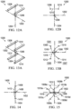
- FIGS. 12 A, 12 B, 13 A, 13 B, 14 , and 15 illustrate various configurations of multiple FFMC tubes in vibration control systems, in accordance with some embodiments of the present disclosure.
- FIGS. 16 , 17 , 18 , and 19 illustrate details of multiple frequency vibration absorbers, in accordance with some embodiments of the present disclosure.
- FIGS. 20 A, 20 B, 20 C, 21 A, 21 B, 22 , 23 , 24 , 25 A, 25 B, 25 C, 26 , 27 A, 27 B, 28 A, 28 B, and 28 C illustrate details of vibration control systems that utilize FFMC tubes to damp vibration of an aircraft wing.
- FIGS. 29 A, 29 B, 29 C, 30 A, 30 B, 31 A, 31 B, 32 A, and 32 B illustrate details of vibration control systems that utilize FFMC tubes to damp vibration of an aircraft empennage.
- FIGS. 1 A and 1 B illustrate an example of an aircraft, which in this case is a rotorcraft 101 .
- FIG. 1 A illustrates a side view of rotorcraft 101
- FIG. 1 B illustrates a perspective view of rotorcraft 101 .
- Rotorcraft 101 has a rotor system 103 with a plurality of rotor blades 105 . The pitch of each rotor blade 105 can be managed or adjusted in order to selectively control direction, thrust, and lift of rotorcraft 101 .
- Rotorcraft 101 further includes a fuselage 107 , anti-torque system 109 , an empennage 111 , and a tail structure 120 .
- tail structure 120 can represent a horizontal stabilizer.
- Torque is supplied to rotor system 103 and anti-torque system 109 using one or more engines. Each engine can apply a torque to the rotor system 103 to rotate the rotor blades 105 at a rotational frequency.
- FIG. 2 illustrates a perspective view of an example of an aircraft, which in this case is a tiltrotor aircraft 201 .
- Tiltrotor aircraft 201 include nacelles 203 a and 203 b , a wing 205 , a fuselage 207 , empennage 213 , and a stabilizer structure 220 .
- Each nacelle 203 a and 203 b can include an engine and gearbox for driving rotor systems 211 a and 211 b , respectively.
- the engines can apply a torque to rotor systems 211 a and 211 b , respectively, to rotate rotor blades at a rotational frequency.
- Nacelles 203 a and 203 b are each configured to rotate between a helicopter mode, in which the nacelles 203 a and 203 b are approximately vertical (as illustrated in FIG. 2 ), and an airplane mode, in which the nacelles 203 a and 203 b are approximately horizontal.
- the helicopter mode the nacelle 203 a and 203 b and the rotor systems 211 a and 211 b are positioned substantially vertical to provide a lifting thrust.
- the nacelle 203 a and 203 b and the rotor systems 211 a and 211 b are positioned substantially horizontal to provide a forward thrust in which a lifting force is supplied by the wing 205 .
- tiltrotor aircraft 201 can be operated such that the nacelle 203 a and 203 b and the rotor systems 211 a and 211 b are selectively positioned between airplane mode and helicopter mode, which can be referred to as a conversion mode.
- helicopter mode which can be referred to as a conversion mode.
- the rotor blades of the rotor systems 211 a and 211 b rotate at a first rotational frequency when in the helicopter mode and rotate at a second rotational frequency when in the airplane mode.
- FIG. 3 illustrates a perspective view of an example of an aircraft, which in this case is a jet aircraft 301 .
- the jet aircraft 301 includes a fuselage 303 , wings 305 a and 305 b , and jet propulsion systems 307 a and 307 b , an empennage 313 , a vertical stabilizer 309 , and horizontal stabilizers 311 a and 311 b .
- the jet propulsion systems 307 a and 307 b include fixed jet engines.
- the jet propulsion systems 307 a and 307 b as well as control surfaces on the wings 305 a and 305 b , the vertical stabilizer 309 , and/or the horizontal stabilizers 311 a and 311 b , which can be selectively controlled in order to selectively control direction, thrust, and lift of the jet aircraft 301 .
- the rotorcraft 101 , the tiltrotor aircraft 201 , and the jet aircraft 301 of FIGS. 1 A, 1 B, 2 , and 3 are merely illustrative of a variety of aircraft that can be used to implement embodiments of the present disclosure.
- Other aircraft implementations can include, for example, hybrid aircraft, gyrocopters, drones, a variety of helicopter configurations, among other examples.
- the described embodiments can also be implemented using non-aircraft vehicles and devices.
- Rotor systems are a major source of vibrations affecting an aircraft.
- the engines and transmission apply a torque to the rotor system to rotates the rotor blades at a rotational frequency or “0”.
- the rotor blades collectively cause structures supporting the blades to vibrate.
- such structures subjected to vibrations can include, but are not limited to a mast supporting the blades, an airframe to which the mast is attached, an empennage or a tail boom attached to the airframe, a wing supporting the rotor system, and the like.
- the frequency of such vibrations is sometimes referred to as N per revolution and is commonly abbreviated and referred to herein as “N-per-rev.”
- N-per-rev is a function of, among other things, the number of blades, “N”, in the rotor system, i.e., assuming identical rotor blades are equally spaced around a rotor hub and moving at a constant rotational velocity.
- N-per-rev is a frequency that is an integer multiple of the rotational frequency, ⁇ , of the rotor system, where the integer is the number of blades in the system.
- ⁇ the rotational frequency
- a rotor system operating at a rotational frequency of 5 Hz and comprising 3 blades has an N-per-rev equal to 3*5 Hz or 15 Hz.
- a rotor system operating at the same rotational frequency and comprising 5 blades has an N-per-rev equal to 5*5 Hz or 25 Hz.
- the operational frequency is also referred to as 1-per-rev.
- Other integer multiples of the rotational frequency can have a dramatic impact on the vibration of components of an aircraft.
- 2-per-rev is 2 ⁇ the rotational frequency, which in the above example is 2*5 or 10 Hz; the 3-per-rev is 3 ⁇ the rotational frequency, which in the above example is 3*5 or 15 Hz; etc. While the other vibration components contribute to overall vibrations of the aircraft, in many cases, n-per-rev is a dominant source of vibrations (e.g., in terms of design loads).
- an aircraft component may have a first natural frequency is does not coincide with an operational frequency of an aircraft, it can still experience vibrations during the operation of the aircraft.
- Some aircraft components such as wings and empennages may have low inherent damping, which can cause the vibrations to decay slowly. Consequently, the aircraft components may be fitted with vibration control systems to mitigate such vibrations.
- a weight is selected to counteract vibration at a particular frequency.
- Such a weight when its mass is selected to counteract vibration at the particular frequency, is sometimes referred to as a “tuned mass.”
- the tuned mass acts in a manner similar to a pendulum that can vibrate out-of-phase with the particular frequency and, thereby, provide an inertial force that counteracts vibrations at the particular frequency.
- a tuned mass can add significant weight to the aircraft, which could potentially reduce the operation efficiency of the aircraft and place additional stress on structural components that support such masses.
- a tuned mass is necessarily tuned to a particular frequency, it may be ineffective for counteracting vibrations at other frequencies. Indeed, a tuned mass system, which is tuned for a particular frequency, may actually exacerbate vibrations frequencies outside of the particular frequency.
- a solution to the above-identified challenges (and others) disclosed herein includes vibration control systems that rely on inertia and/or resistance provided by moving a working fluid through a fluidic flexible matrix composite (FFMC) tube (also known as F 2 MC tubes).
- FFMC fluidic flexible matrix composite
- Embodiments of the present disclosure rely on inertance and resistance of a fluidic circuit, which are analogous to mass and damping properties in a mechanical vibration control system, to absorb vibrations.
- a damper includes structural damping, which dissipates energy to reduce the vibrations.
- Some dampers of the present disclosure utilize the resistance of the fluidic circuit between FFMC tubes to dissipate energy and, thereby, reduce vibrations.
- An absorber counteracts vibrations based on inertia of an object such as a mass.
- Some absorbers of the present disclosure utilize the inertance produced by FFMC tubes cyclically pumping a working fluid through a fluidic circuit between FFMC tubes to counteract vibration. Analogous to a pendulum, absorbers of the present disclosure can pump the working fluid out-of-phase with the vibration that it counteracts. Some embodiments of the present disclosure utilize an adjustable orifice to control the resistance of the fluidic circuit, which can be used to tune the damping characteristics of the system to multiple frequencies. While some traditional systems are tuned for a single frequency, embodiments of the present disclosure are advantageously tunable to two or more frequencies and/or a range of frequencies.
- the following figures provide details of the construction of fluidic flexible matrix composite (FFMC) tubes and their use in absorbers and dampers of the present disclosure.
- FIG. 4 illustrates a portion of an anisotropic flexible matrix composite material 400 (i.e., the anisotropic composite material 400 ) in a three-dimensional coordinate system comprising axes X, Y, and Z.
- the anisotropic composite material 400 comprises multiple layers of strands that, together, contribute to the thickness ti.
- the strands may be made of carbon, steel, or another high strength material.
- Each of the multiple layers comprises strands oriented at an angle, ⁇ , relative to the X axis in FIG. 4 .
- Alternating layers may be aligned at equal and opposite values of the angle ⁇ for example, +45° and ⁇ 45°. In other specific examples, the angle ⁇ may be 15, 30, 40, or 55.
- the axes labeled 1 and 2 in the FIG. 4 correspond to a local coordinate system that is aligned with the angle ⁇ of the strands. Winding the strands in the alternating layers generates the anisotropic composite material 400 and imparts structural properties that are different in each of the axes 1 and 2 .
- the Young's moduli in a direction parallel to axis 1 may be a first value and the Young's moduli in a direction perpendicular to axis 1 and parallel to axis 2 may be a second value.
- the anisotropic composite material 400 is stiffer in one direction, such as parallel to axis 1 , than in another direction, such as parallel to axis 2 . Because of the anisotropic properties of the anisotropic composite material 400 , the anisotropic composite material 400 can be used to form a portion of a fluidic flexible matrix composite (FFMC) tube, which can produce an internal pressure and change volume based on an axial strain. An example of such a tube is described below with respect to FIGS. 5 A and 5 B .
- FFMC fluidic flexible matrix composite
- FIGS. 5 A and 5 B illustrate various details of a fluidic flexible matrix composite (FFMC) tube 500 , in accordance with some embodiments of the present disclosure.
- FIG. 5 A is a three-dimensional view of a portion of the FFMC tube 500 .
- FIG. 5 B is a transverse cross-section of the FFMC tube 500 of FIG. 5 A .
- the FFMC tube 500 comprises a tube of the anisotropic composite material 400 (of FIG. 4 ) having an outer radius r 1 and a bladder 502 having an outer radius r 2 . Together, the anisotropic composite material 400 and the bladder 502 enclose a working fluid 504 having an outer radius r 3 .
- the bladder 502 is nested within the tube of the anisotropic composite material 400 .
- the bladder 502 is made of a compliant material such as rubber or polyurethane and seals the working fluid 504 within the FFMC tube 500 .
- the working fluid 504 may be a high density and low viscosity fluid such as a liquid coolant (e.g., a fluorocarbon oil).
- a liquid coolant e.g., a fluorocarbon oil.
- a tensile axial strain applied to the FFMC tube causes a volume of the FFMC tube to decrease
- compressive axial strain applied to the FFMC tube causes the volume of the FFMC tube to increase.
- the tube of the anisotropic composite material 400 can operate to pump the working fluid through a fluidic circuit based on axial strains, e.g., as is described in further detail below with respect to FIGS. 6 , 7 A, 7 B , and 7 C.
- FIG. 6 illustrates a longitudinal cross-section through a fluidic flexible matrix composite (FFMC) tube 600 , in accordance with some embodiments of the present disclosure.
- the FFMC tube 600 comprises an anisotropic composite tube 602 , a bladder 604 , end fittings 616 and 610 , attachment fittings 618 and 612 , a conduit fitting 614 , sealant clamps 606 a and 606 b , and attachment crimps 608 a and 608 b .
- the sealant clamps 606 a and 606 b attach the anisotropic composite tube 602 and the bladder 604 to the end fittings 616 and 610 , respectively.
- the sealant clamps 606 a and 606 b create a liquid tight-seal to retain fluid (such as a working fluid) in an internal channel 624 . Threads on the attachment fittings 612 and 618 interlock with threads on the end fittings 610 and 616 , respectively.
- the attachment crimp 608 a attaches the anisotropic composite tube 602 around the attachment fittings 612 and the end fitting 610 .
- the attachment crimp 608 b attaches the anisotropic composite tube 602 around the attachment fittings 618 and the end fitting 616 . Threaded ends of the attachment fittings 618 and 612 extend out from the attachment crimps 608 a and 608 b .
- threaded ends are configured to attach the FFMC tube 600 to another object such as an aircraft component.
- fasters such as nuts, washers and the like may be utilized attached to the exposed threaded ends of the attachment fittings 618 and 612 to a plate, which is coupled to an aircraft component, or may be directly coupled to the aircraft component.
- the conduit fitting 614 is configured to fluidically couple the FFMC tube 600 to a conduit in fluidic circuit.
- a nominal length L 2 of the FFMC tube 600 is measured between extreme ends of the attachment crimps 608 a and 608 b .
- An effective length L 1 of the FFMC tube 600 is measured between obstructions to the volume change of the FFMC tube 600 , which in this case is the end fittings 610 and 616 .
- the effective length L 1 may be selected to damp or absorb vibrations at a desired frequency.
- the effective length L 1 varies as the FFMC tube 600 changes volume when pumping a working fluid as illustrated in FIGS. 7 A, 7 B, and 7
- FIGS. 7 A, 7 B, and 7 C illustrate the FFMC tube 600 pumping a working fluid, in accordance with some embodiments of the present disclosure.
- FIG. 7 A illustrates the FFMC tube 600 in a neutral state where no axial strain is applied to the FFMC tube 600 .
- the effective length L 1 is unchanged (e.g., relative to FIG. 6 ) and the outside diameter of the FFMC tube is D 1 .
- the angle ⁇ determines the structural properties of an anisotropic composite material comprised in an FFMC tube and, therefore, determines some dynamic behavior of the FFMC tube.
- FIGS. 7 A illustrates the FFMC tube 600 pumping a working fluid, in accordance with some embodiments of the present disclosure.
- FIG. 7 A illustrates the FFMC tube 600 in a neutral state where no axial strain is applied to the FFMC tube 600 .
- the effective length L 1 is unchanged (e.g., relative to FIG. 6 ) and the outside diameter of the FFMC tube
- FIG. 7 B illustrates a compressive axial strain C 1 applied to the FFMC tube 600 .
- the FFMC tube 600 increases volume of the FFMC tube 600 and a maximum outside diameter of the FFMC tube is D 2 , which is greater than the outside diameter D 1 of the neutral state.
- the effective length L 3 decreases relative to the neutral state, i.e., L 1 >L 3 .
- the FIG. 7 C illustrates a tensile axial strain T 1 applied to the FFMC tube 600 . Under the tensile axial strain T 1 the FFMC tube 600 decreases volume of the FFMC tube 600 and a minimum outside diameter of the FFMC tube is D 3 , which is less than the outside diameter D 1 of the neutral state.
- the effective length 1.4 increases relative to the neutral state, i.e., L 4 >L 1 .
- the FFMC tube 600 is filled with a working fluid.
- a working fluid e.g., shortened or stretched
- the constraining effect of the multiple layers of strands in the FFMC tube 600 allows the FFMC tube 600 to pump up to two orders of magnitude more fluid per unit axial strain than can a piston of the same diameter.
- a small mass of fluid being pumped by the FFMC tubes can provide the same effect as a large inertia from a relatively large mass.
- Two or more FFMC tubes may be coupled to one another by a fluidic circuit including one or more conduits and a valve.
- the valve can change the resistance to flow through the fluidic circuit. Flow resistance caused by the valve the fluidic circuit as well as frictional losses the conduits can contribute to damping provided by a vibration control system using FFMC tubes. While the overall mass of the working fluid remains constant because it is contained by the fluidic circuit and tubes, the stiffness and damping provided by the system can be varied based on changing the size of the orifice, e.g., in real time. Because the FFMC tubes change volume in response to axial strain, they pump fluid through the fluidic circuit to create fluid inertance.
- each of stiffness, mass, and damping are tunable.
- the stiffness is tunable based on a length and a diameter of the FFMC tube
- the mass is tunable based on the amount of working fluid used in the system
- damping is tunable based on a length conduit in the fluidic matrix, among other things.
- the variety of tunable characteristics provided by such a system enables more flexibility and customization that is offered with traditional vibration control systems.
- FIG. 8 is simplified component diagram of vibration control system 800 .
- the vibration control system 800 includes FFMC tubes 802 and 804 fluidically coupled to a fluidic circuit 806 .
- the fluidic circuit 806 includes conduits 808 , 810 , and 812 , a valve 814 , and a reservoir 816 .
- the fluidic circuit 806 is operable to carry a capacity of a working fluid between the FFMC tubes 802 and 804 and the reservoir 816 via the valve 814 .
- Each of the FFMC tubes 802 and 804 include an anisotropic composite material that enables them to pump a working fluid, e.g., as described with respect to FIGS. 7 A, 7 B, and 7 C .
- the working fluid circulates through the fluidic circuit 806 based on the pumping action of the FFMC tubes 802 and 804 .
- the conduit 808 is coupled between the FFMC tube 802 and the valve 814 .
- the conduit 810 is coupled between the FFMC tube 804 and the valve 814 .
- the conduit 812 is coupled between the valve 814 and the reservoir 816 .
- the valve 814 is positioned between the FFMC tubes 802 and 804 in the fluidic circuit 806 .
- the valve 814 is operable to open and close to control a resistance to flow of the working fluid through the conduits 808 , 810 , and 812 . This resistance to flow may be increases or decreases to increase or decrease the damping provided by the vibration control system 800 .
- valve 814 may be set to a closed position to completely obstruct an orifice in valve 814 (i.e., setting relatively high damping), an open position to completely open the orifice (i.e., setting relatively low damping), or one or more intermediate positions between the first position and the second position.
- the reservoir 816 can hold a capacity of liquid that is pumped from the FFMC tubes 802 and 804 .
- the FFMC tubes 802 and 804 may draw liquid from the reservoir 816 as they fill with liquid.
- the valve may be set to a specific position manually, e.g., by a maintenance person.
- each of the FFMC tubes 802 and 804 is based on the relative displacement the other. For example, when both of the FFMC tubes 802 and 804 experience approximately the same axial strain (e.g., same magnitude and direction), the FFMC tubes 802 and 804 will pump in the same direction and will fill or draw working fluid from the reservoir 816 . Such a situation may occur, e.g., when both of the FFMC tubes 802 and 804 are placed on the same side of a neutral axis of a bending beam (see, e.g., FIGS. 12 A and 12 B below).
- the FFMC tubes 802 and 804 experience approximately equal and opposite axial strains, the FFMC tubes 802 and 804 will pump in the opposite directions and will exchange the working fluid in approximately amounts from one another and will neither fill nor draw working fluid from the reservoir 816 .
- the FFMC tubes 802 and 804 are placed on the opposite side of a neutral axis of a bending beam (see, e.g., FIG. 14 ).
- the vibration control system 800 may exclude the reservoir 816 and, instead, the conduit 812 may serve as a linear reservoir or an inertia track in which the working fluid can accumulate as needed based on the pumping of the FFMC tubes 1608 a and 1608 b .
- the frictional losses experienced by the working fluid along the length of the inertia track can also contribute to the damping provided by the vibration control system 800 .
- the vibration control system 800 provides damping to an aircraft component based on fluid resistance of the fluidic circuit 806 .
- an aircraft component may have low inherent damping, which can cause vibrations introduced to the aircraft component to decay slowly.
- the damping provided by frictional losses of a working fluid flowing through the conduits 808 , 810 , and 812 can be used to add damping to the aircraft component.
- the added damping can increase total damping (e.g., the sum of inherent damping and added damping) to equal or exceed a threshold value.
- Damping provided by the fluidic circuit 806 can be adjusted based on several factors including, e.g., a position of the valve 814 , a diameter of one or more of the conduits 808 , 810 , and 812 , a length of one or more of the conduits 808 , 810 , and 812 , and/or combinations thereof. One or more of the factors may be used to tune the damping to a particular level.
- the valve 814 is movable between an open position to completely open an orifice through which the working fluid can flow; a closed position to completely obstruct the orifice; and a plurality of intermediate positions between the open position and the closed position.
- the intermediate positions can correspond to fractions of open and/or closed and may be adjusted to increase or decrease the frictional losses in the fluidic circuit 806 .
- the valve may add little or no frictional losses when in the open position (e.g., a minimum value). The frictional losses increase as the valve is moved from the open position toward the closed position (i.e., through the intermediate positions).
- the length and radius of the inertia track e.g., conduit 812 ) can be used to adjust the inertance of the working fluid and/or the resistance of the fluidic circuit 806 .
- the inertance provided by the working fluid is inversely proportional to the square of the radius (e.g., r2) of the inertia track and is proportional to a length of the inertia track.
- the resistance of the fluidic circuit 806 is inversely proportional to the r4 of the inertia track.
- damping increases as the radius of a conduit decreases. A large radius corresponds to low flow resistance and, therefore, lower damping. A small radius corresponds to high flow resistance and, therefore, higher damping.
- the track is designed to provide a desired level of inertance with relatively low damping provided by the inertia track.
- valve is used a primary source of flow resistance and therefore, damping in the vibration control system 800 .
- Some exemplary models, designs, and design processes related to FFMC tubes and fluidic circuits are discussed in a 2016 thesis by Kentaro Miura titled, “MODELING, DESIGN, AND EXPERIMENTAL VALIDATION OF A TAILBOOM VIBRATION ABSORBER USING FLUIDIC FLEXIBLE MATRIX COMPOSITE TUBES,” which is hereby incorporated by reference in its entirety.
- FIG. 9 is simplified component diagram of a vibration control system 900 .
- the vibration control system 900 includes FFMC tubes 902 and 904 fluidically coupled to a fluidic circuit 906 .
- the fluidic circuit 906 includes conduits 908 , 910 , and 912 , valve 914 , and a reservoir 916 .
- Many components of the FIG. 9 are similar to corresponding components in the FIG. 8 ; the description of such components is not repeated here only for the sake of brevity.
- a difference from the vibration control system 800 of FIG. 8 is that the vibration control system 900 of FIG. 9 includes a processing unit 918 .
- the processing unit includes a controller 920 , a sensor 922 , a processor 924 , and a memory 926 .
- the controller 920 is operable to actively control absorption and/or damping of vibrations via the FFMC tubes 902 and 904 based on actuating the valve 914 .
- the controller 920 may comprise an active control device such as a servomotor to open and close the valve 914 .
- the controller 920 may utilize the processor 924 to receive, process, and execute actions based on readings from the sensor 922 .
- the sensor 922 may include an accelerometer, a gyroscope, or other sensor operable of directly or indirectly detecting vibrations and/or vibration frequency.
- the controller 920 may actively control absorption and/or damping of the vibration via the FFMC tubes 902 and 904 by: opening the valve 914 to decrease the stiffness of the FFMC tubes 902 and 904 based on the sensor 922 detecting that the vibration is in a first frequency range, opening the valve 914 to increase the stiffness of the FFMC tubes 902 and 904 based on the sensor 922 detecting that the vibration is in a second frequency range.
- the controller 920 eliminates the need for manual control of the valve 914 . Instead, the controller 920 can dynamically (e.g., in near real-time) modify the stiffness of the FFMC tubes 902 and 904 .
- Such modification can occur while an aircraft on which the controller 920 is located is airborne. This can significantly reduce vibrations for a wide range of frequencies, which can improve the service life of an aircraft component to which the system is connected.
- the controller 920 can actively set the stiffness of the FFMC tubes 902 and 904 to a first value based on a tiltrotor aircraft operating in helicopter mode (i.e., at a first operational frequency) and, at another point in time, actively set the stiffness of the FFMC tubes 902 and 904 to a second value based on a tiltrotor aircraft operating in airplane mode (i.e., at a second operational frequency).
- the processor 924 executes instructions from the memory 926 and/or other memory elements such as other memory accessible to the vibration control system 900 .
- the processor 424 may comprise a microprocessor, controller, an application-specific integrated circuit (ASIC), a field programmable gate array (FPGA), digital signal processor (DSP), or any other suitable computing device, resource, or combination of hardware, stored software and/or encoded logic operable to process data.
- ASIC application-specific integrated circuit
- FPGA field programmable gate array
- DSP digital signal processor
- the memory 926 may comprise any form of volatile or non-volatile memory including, without limitation, magnetic media (e.g., one or more tape drives), optical media, random access memory (RAM), read-only memory (ROM), flash memory, removable media, an erasable programmable read only memory (EPROM), an electrically erasable programmable ROM (EEPROM)), a memory element in an application-specific integrated circuit (ASIC), a memory element in a field programmable gate array (FPGA), or any other suitable memory component or components.
- the memory stores executable instructions that relate the readings from the sensor 922 to a state of the valve 914 .
- the controller 920 and/or the processor 924 cooperate to execute such instructions.
- the memory 926 may store a correspondence such as a table between a frequency of a vibration a position of a valve in a fluidic circuit. The controller 920 may sets the position of the valve based on the correspondence.
- logic may be encoded in one or more tangible media, which may be inclusive of non-transitory tangible media and/or non-transitory computer readable storage media (e.g., embedded logic provided in an ASIC, embedded logic provided in an FPGA, logic provided digital signal processing instructions, in software [potentially inclusive of object code and source code] to be executed by a processor, or other similar machine, etc.).
- tangible media e.g., embedded logic provided in an ASIC, embedded logic provided in an FPGA, logic provided digital signal processing instructions, in software [potentially inclusive of object code and source code] to be executed by a processor, or other similar machine, etc.
- FIGS. 8 and 9 illustrate the vibration control systems 800 and 900 , respectively, each having two FFMC tubes.
- embodiments of the present disclosure are not limited to such embodiments.
- the teachings of the present disclosure are applicable to various numbers and configurations of FFMC tubes.
- Some embodiments of the present disclosure may include 1, 2, 4, 8, 10, or any other number of FFMC tubes.
- FIG. 10 is simplified component diagram of a vibration control system 1000 , which includes four FFMC tubes 1002 , 1004 , 1006 , and 1008 fluidically coupled to a fluidic circuit 1010 .
- the fluidic circuit 1010 includes conduits, a valve 1012 , and a processing unit 1014 .
- Many components of the FIG. 10 are similar to corresponding components in the FIG. 9 ; the description of such components is not repeated here only for the sake of brevity.
- FIGS. 11 A and 11 B illustrate simplified diagrams of a system 1100 including a cantilevered beam 1108 , in accordance with some embodiments of the present disclosure.
- FIG. 11 A illustrates the system 1100 when the cantilevered beam 1108 is in an undeformed state.
- the system 1100 includes a supporting structure 1110 , the cantilevered beam 1108 , FFMC tubes 1102 a and 1102 b , and a fluidic circuit 1106 .
- the cantilevered beam 1108 is rigidly attached to the supporting structure 1110 such as by fasteners and/or welds.
- Each of the FFMC tubes 1102 a and 1102 b is rigidly coupled to the cantilevered beam 1108 at a position that is offset from a neutral axis of the cantilevered beam 1008 a distance O 1 .
- the fluidic circuit 1106 fluidically couples the FFMC tubes 1102 a and 1102 b to one another.
- the fluidic circuit 1106 includes a valve 1116 , which may be selectively opened or closed to change the resistance to flow of a working fluid through the fluidic circuit 1106 .
- each of the FFMC tubes 1102 a and 1102 b is in a neutral state, e.g., as described with respect to FIG. 7 A .
- Each of the FFMC tubes 1102 a and 1102 b are configured to damp a vibration of the cantilevered beam 1108 based on a stiffness of the respective FFMC tube.
- the stiffness of the FFMC tubes 1102 a and 1102 b is a function of at least the fluid resistance of the fluidic circuit 1106 .
- the cantilevered beam 1108 may correspond to an aircraft component that is subjected to vibrations during operation of an aircraft. The vibrations cause the cantilevered beam 1108 to oscillate between deflecting in an upward direction and deflecting in a downward direction relative to that shown in FIG. 11 A .
- the variation of stiffness and damping in the fluidic circuit 106 allows for a tuned response at multiple frequencies by manipulating the valve 1116 . By opening or closing the valve 1116 , the natural frequency of the system can be changed.
- FIG. 11 B illustrates the system 1100 when cantilevered beam 1108 is in a deformed state and is deflecting in a downward direction.
- the FFMC tube 1102 a is coupled to a top of the cantilevered beam 1108 .
- the FFMC tube 1102 b coupled to a bottom of the cantilevered beam 1108 .
- the top of the cantilevered beam 1108 elongates and the bottom of the cantilevered beam 1108 shortens.
- the FFMC tube 1102 a receives a tensile axial strain and the FFMC tube 1102 b receives a compressive axial strain from the cantilevered beam 1108 .
- the strains are equal and opposite to one another.
- Each of the FFMC tubes 1102 a and 1102 b pump a working fluid though the fluidic circuit 1106 based on the axial strains.
- the FFMC tube 1102 a decreases in volume, which pumps the working fluid from the FFMC tube 1102 a into the fluidic circuit 1106 based on the tensile axial strain, e.g., as illustrated in FIG. 7 C .
- the FFMC tube 1102 b increases in volume, which sucks the working fluid into FFMC tube 1102 b from the fluidic circuit 1106 based on the compressive axial strain, e.g., as illustrated in FIG. 7 B .
- the pumping and suction by the FFMC tubes 1102 a and 1102 b balance one another and force the working fluid to move from the FFMC tube 1102 a toward the FFMC tube 1102 b .
- the cantilevered beam 1108 may be oscillate between deflecting in the downward direction and the deflecting in an upward direction where the strains experienced by the FFMC tubes 1102 a and 1102 b is reversed, i.e., the FFMC tube 1102 a receives a compressive axial strain and the FFMC tube 1102 b receives a tensile axial strain.
- the working fluid may be cycled back and forth between the FFMC tubes 1102 a and 1102 b via the fluidic circuit 1106 .
- FIGS. 12 A, 12 B, 13 A, 13 B, 14 , and 15 illustrate various configurations in which multiple FFMC tubes may be coupled to an aircraft component to provide vibration control in a vibration control system, in accordance with some embodiments of the present disclosure.
- FIGS. 12 A and 12 B illustrate a configuration 1200 of two FFMC tubes 1208 and 1210 coupled by a fluidic circuit 1212 .
- FIG. 12 A is a three-dimensional view of the configuration 1200 .
- FIG. 12 B is a front view of the configuration 1200 .
- the configuration 1200 is organized around a set of axes 1202 and 1204 which pass through a neutral point 1206 of an aircraft component (not shown).
- a neutral point may be inclusive of a centroid of a cross sectional shape, an intersection of a vertical neutral axis and a horizontal neutral axis, a center of stiffness of the aircraft component, or another geometric, structural, or analytical neutral point of an aircraft component.
- the location the FFMC tubes 1208 and 1210 is symmetric with respect to the neutral point 1206 .
- the symmetric configuration prevents the stiffness provided by the FFMC tubes 1208 and 1210 from introducing lateral eccentricities that could erroneously induce torsion while the FFMC tubes 1208 and 1210 control vibrations of the aircraft component.
- FIGS. 13 A and 13 B illustrate a configuration 1300 of four FFMC tubes 1308 , 1310 , 1312 , and 1314 .
- FIG. 13 A is a three-dimensional view of the configuration 1300 .
- FIG. 13 B is a front view of the configuration 1300 .
- the configuration 1300 is organized around axes 1302 and 1304 which pass through a neutral point 1306 of an aircraft component (not shown).
- the axes 1302 and 1304 divide the cross section into quadrants 1301 , 1303 , 1305 , and 1307 .
- Each of the FFMC tubes 1308 , 1310 , 1312 , and 1314 is coupled to the aircraft component and configured to damp a torsional vibration of the aircraft component based on the FFMC tubes being fluidically coupled to one another and positioned in different ones of the quadrants that are located diagonal to one another.
- the FFMC tubes 1308 and 1314 are fluidically coupled to one another by a fluidic circuit 1316 and are located in quadrants 1301 and 1307 , respectively, which are diagonal to one another.
- the FFMC tubes 1310 and 1312 are fluidically coupled to one another by a fluidic circuit 1318 and are located in quadrants 1303 and 1305 , respectively, which are diagonal to one another.
- the FFMC tubes are divided into two pairs that are fluidically coupled between quadrants located diagonally from one another.
- the fluidic circuits 1316 and 1318 are independent and are isolated from one another.
- each of the fluidic circuits 1316 and 1318 includes the components as described with respect to the fluidic circuits of FIG. 8 . In other embodiments, each of the fluidic circuits 1316 and 1318 includes the components as described with respect to the fluidic circuits of FIG. 9 .
- Each of the FFMC tubes is configured to receive an axial deformation based on the torsional vibration.
- the configuration 1300 can directly damp the torsional vibration, which may cause twisting that induces equal and opposite axial strains in quadrants of the aircraft component that are at diagonal positions relative to one another.
- the FFMC tube 1308 may receive a tensile axial strain based on the torsional vibration while, simultaneously, the FFMC tube 1314 receives a compressive axial strain based on the torsional vibration (or vice versa).
- the FFMC tube 1310 may receive a tensile axial strain based on the torsional vibration while, simultaneously, the FFMC tube 1312 receives compressive axial strain based on the torsional vibration (or vice versa).
- FIG. 14 illustrates a front view of a configuration 1400 of two FFMC tubes 1408 and 1410 coupled by a fluidic circuit 1412 .
- the configuration 1400 is organized around a set of axes 1402 and 1404 which pass through a neutral point 1406 of an aircraft component (not shown).
- the location the FFMC tubes 1408 and 1410 is symmetric with respect to the neutral point 1406 .
- the symmetry of the configuration 1400 prevents the stiffness provided by the FFMC tubes 1408 and 1410 from introducing lateral or vertical eccentricities that could erroneously induce torsion while the FFMC tubes 1408 and 1410 control vibrations of the aircraft component.
- FIG. 15 a front view of a configuration 1500 of eight FFMC tubes 1508 a , 1508 b , 1508 c , 1508 d , 1512 a , 1512 b , 1512 c , and 1512 d .
- the configuration 1500 is organized around axes 1502 and 1504 which pass through a neutral point 1506 of an aircraft component (not shown).
- the FFMC tubes 1508 i.e., 1508 a , 1508 b , 1508 c , and 1508 d
- the FFMC tubes 1508 are coupled via a fluidic circuit 1512 .
- the FFMC tubes 1510 are coupled via a fluidic circuit 1516 . Because the FFMC tubes 1508 are offset farther from the axis 1502 than the FFMC tubes 1510 , the FFMC tubes 1508 may more efficiently damp vertical vibrations than the FFMC tubes 1510 , e.g., due to the FFMC tubes 1508 having a longer moment arm distance relative to the axis 1502 .
- the FFMC tubes 1510 may more efficiently damp horizontal vibrations than the FFMC tubes 1508 , e.g., due to the FFMC tubes 1508 having a longer moment arm distance relative to the axis 1504 .
- the configuration 1500 may simultaneously damp vertical vibrations based on the FFMC tubes 1508 , lateral vibrations based on the FFMC tubes 1510 , and torsional vibrations based on a combination of the FFMC tubes 1508 and 1510 .
- FIGS. 16 and 17 illustrate details of multiple frequency vibration absorber 1600 coupled to an aircraft component 1602 , in accordance with some embodiments of the present disclosure.
- FIG. 16 is a three-dimensional view of the multiple frequency vibration absorber 1600 .
- FIG. 17 is a side view of the multiple frequency vibration absorber 1600 .
- the aircraft component 1602 may be coupled to an aircraft and may receive vibrations from the aircraft such as 1-per-rev, 2-per-rev, N-per-rev, or other vibrations.
- the multiple frequency vibration absorber 1600 is operable to absorb at least a portion of the vibrations of the aircraft component 1602 which can reduce the perceived vibration of the aircraft component 1602 .
- the multiple frequency vibration absorber 1600 includes a beam element 1604 , a mass 1606 , fluidic flexible matrix composite (FFMC) tubes 1608 a and 1608 b , attachment plates 1610 a and 1610 b , a controller 1612 , a fluidic circuit 1620 , and a sensor 1622 .
- the beam element 1604 is attached to the aircraft component 1602 .
- the mass 1606 is rigidly attached to the beam element 1604 and is configured to tune a natural frequency of the beam element 1604 . Because the mass 1606 is rigidly attached to the beam it is fixed and stationary relative to the beam element 1604 (e.g., the mass 1606 does not move axially along the length of the beam element).
- the attachment plates 1610 a and 1610 b couple the FFMC tubes 1608 a and 1608 b to the beam element 1604 .
- the attachment plates 1610 a and 1610 b may be coupled to the beam element 1604 by a faster, a weld, and the like.
- the sensor 1622 is operable to detect a frequency of a vibration of the aircraft component.
- the FFMC tubes 1608 a and 1608 b are configured to absorb the vibration of the aircraft component 1602 based, at least in part, on a stiffness of the FFMC tubes 1608 a and 1608 b and/or the inertance of a working fluid pumped though the fluidic circuit 1620 by the FFMC tubes 1608 a and 1608 b .
- the controller 1612 actively control absorption of the vibration via the FFMC tubes 1608 a and 1608 b by controlling flow of a working fluid through the fluidic circuit 1620 based on frequency data received from the sensor 1622 .
- the fluidic circuit 1620 is fluidically coupled to each of the FFMC tubes 1608 a and 1608 b .
- the fluidic circuit 1620 includes the conduits 1614 a , 1614 b , and 1618 and a valve 1616 .
- the fluidic circuit 1620 is filled with a working fluid, which is pumped based on axial strain experienced by the FFMC tubes 1608 a and 1608 b .
- the conduits 1614 a and 1614 b attach the FFMC tubes 1608 a and 1608 b , respectively, to the conduit 1618 via the valve 1616 .
- the valve 1616 is to control the stiffness of the FFMC tubes 1608 a and 1608 b based on regulating a flow of the working fluid into and out of the FFMC tubes 1608 a and 1608 b .
- the valve 1616 also controls the inertance of the working fluid as it is pumped though the fluidic circuit 1620 .
- the conduit 1618 may serve as a linear reservoir or an inertia track in which the working fluid can accumulate as needed based on the pumping of the FFMC tubes 1608 a and 1608 b .
- the valve 1616 may be a ball valve, a plug valve, a globe valve, and or any other valve including an orifice and a barrier coupled to the orifice being moveable between an open and a closed position.
- the controller 1612 can actively control absorption of the vibration via the FFMC tubes 1608 a and 1608 b based on actuating the valve 1616 .
- the controller 1612 may identify and modify a position of the valve 1616 .
- the controller 1612 can open the valve 1616 to decrease the stiffness of the FFMC tubes 1608 a and 1608 b based on the sensor detecting that the vibration is in a first frequency range and close the valve 1616 to increase the stiffness of the FFMC tubes 1608 a and 1608 b based on the sensor 1622 detecting that the vibration is in a second frequency range.
- the first frequency range is higher than the second frequency range.
- the sensor 1622 and the controller 1612 cooperate in a feedback to actively control the frequency response of the multiple frequency vibration absorber 1600 to various frequencies.
- the FFMC tubes 1608 a and 1608 b absorb the vibration of the aircraft component and change the frequency response (e.g., reduce the maximum displacement) of the aircraft component by dynamically changing the stiffness of the multiple frequency vibration absorber 1600 .
- closing the valve 1616 increases the stiffness of the FFMC tubes based on increasing resistance to the flow of the working fluid through the FFMC tube.
- Opening the valve 1616 decreases the stiffness of the FFMC tube based on decreasing resistance to the flow of the working fluid through the FFMC tube.
- FIG. 18 is a graph of frequency response of the multiple frequency vibration absorber 1600 , in accordance with some embodiments of the present disclosure.
- Curve 1802 illustrates a baseline performance of the multiple frequency vibration absorber 1600 , i.e., without any vibration control system.
- Curve 1806 illustrates the frequency response of the multiple frequency vibration absorber 1600 when the valve 1616 is completely open.
- Curve 1804 illustrates the frequency response of the multiple frequency vibration absorber 1600 when the valve 1616 is completely closed. These curves show that by opening and closing the valve 1616 , the natural frequency of the multiple frequency vibration absorber 1600 can be changed.
- the natural frequency of the multiple frequency vibration absorber 1600 can be tuned between the values of curves 1804 and 1806 by partially opening the valve 1616 .
- the multiple frequency vibration absorber 1600 can be tuned to absorb a desired frequency by using the valve 1616 to set the natural frequency of the multiple frequency vibration absorber 1600 .
- FIG. 19 illustrates a system 1900 in which a multiple frequency vibration absorber is applied to a seat in an aircraft, in accordance with some embodiments of the present disclosure.
- the system 1900 includes a seat, which is attached to and receives vibrations from an aircraft 1906 .
- a multiple frequency vibration absorber 1904 is attached to the seat 1902 .
- the aircraft 1906 may generate vibrations, e.g., at a specific frequency
- the multiple frequency vibration absorber 1904 is tuned to absorb the vibrations at the specific frequency.
- FIGS. 20 A, 20 B, 20 C, 21 A, 21 B, 22 , 23 , 24 , 25 A, 25 B, 25 C, 26 , 27 A, 27 B, 28 A, 28 B, and 28 C illustrate details of vibration control systems that utilize FFMC tubes to damp vibration of an aircraft wing such as the wing 205 of the tiltrotor aircraft 201 of FIG. 2 and/or the wings 305 a and 305 b of the jet aircraft 301 of FIG. 3 .
- FIGS. 20 A, 20 B, and 20 C illustrate a system 2000 in which a vibration control system 2001 is coupled to an external surface 2004 of an aircraft wing 2002 .
- FIG. 20 A is a three-dimensional view of the system 2000 .
- FIG. 20 B is a view of the system 2000 from the viewpoint of the arrows labeled “ 20 B” in FIG. 20 A .
- FIG. 20 C is a view of the system 2000 from the viewpoint of the arrows labeled “ 20 C” in FIG. 20 A .
- the vibration control system 2001 includes FFMC tubes 2008 a and 2008 b , attachment plates 2006 a and 2006 b , and a fluidic circuit 2016 .
- the attachment plates 2006 a and 2006 b attach the FFMC tubes 2008 a and 2008 b to the external surface 2004 of the aircraft wing 2002 in a configuration that corresponds to the configuration 1200 of FIGS. 12 A and 12 B .
- the attachment plates 2006 a and 2006 b also couple the FFMC tubes 2008 a and 2008 b to one another, which can cause the FFMC tubes 2008 a and 2008 b receive approximately the same strain and therefore produce balanced inertance effects that do not introduce eccentricities in the stiffness provided by the vibration control system 2001 .
- the fluidic circuit 2016 includes conduits 2010 a , 2010 b , 2014 , and valve 2012 .
- the vibration control system 2001 includes FFMC tubes 2008 a and 2008 b , attachment plates 2006 a and 2006 b , and a fluidic circuit 2016 .
- Many components of the vibration control system 2001 of FIG. 20 are similar to corresponding components in the vibration control system 800 of FIG. 8 ; the description of such components is not repeated here only for the sake of brevity.
- the FFMC tubes 2008 a and 2008 b in the vibration control system 2001 are operable damp vibrations of the aircraft wing 2002 based on a stiffness of the FFMC tubes 2008 a and 2008 b , which can be controlled, at least in part, by the setting a position of the valve 2012 .
- the vibration control system 2001 is passive and the valve 2012 is, e.g., manually operated.
- the vibration control system 2001 is active or semi-active and includes a processing unit such as the processing unit 918 of FIG. 9 to actively control damping vibrations of the aircraft wing 2002 via the FFMC tubes 2008 a and 2008 b based on actuating the valve 2012 .
- a processing unit such as the processing unit 918 of FIG. 9 to actively control damping vibrations of the aircraft wing 2002 via the FFMC tubes 2008 a and 2008 b based on actuating the valve 2012 .
- FIGS. 20 A, 20 B, and 20 C illustrate two FFMC tubes coupled to the same side of an aircraft wing
- FIGS. 21 A and 21 B illustrate FFMC tubes coupled to the opposite sides of an aircraft wing.
- FIGS. 21 A and 21 B illustrate a system 2100 in which a vibration control system 2101 is coupled to an external surface 2104 of an aircraft wing 2102 .
- FIG. 21 A is a three-dimensional view of the system 2100 .
- FIG. 21 B is a view of the system 2100 from the viewpoint of the arrows labeled “ 21 B” in FIG. 21 A .
- the vibration control system 2101 includes FFMC tubes 2106 , 2108 , 2112 , and 2110 and attachment plates 2114 a , 2114 b , 2116 a , 2116 b , 2118 a , 2118 b , 2120 a , and 2120 b , and at least one fluidic circuit (not shown).
- the attachment plates attach the FFMC tubes to the external surface 2104 of the aircraft wing 2102 in a configuration that corresponds to the configuration 1300 of FIGS. 13 A and 13 B .
- the fluidic circuit of the vibration control system 2101 may be configured in various ways.
- the fluidic circuit of the vibration control system 2101 includes the components as described with respect to the fluidic circuits of FIG. 10 .
- the vibration control system 2101 includes two or more fluidic circuits that couple diagonal pairs of the FFMC tubes 2106 , 2108 , 2110 , and 2112 to damp torsional vibrations such as the fluidic circuits 1316 and 1318 as described with respect to the fluidic circuits of FIGS. 13 a and 13 B.
- any subset or combination of the FFMC tubes 2106 , 2108 , 2110 , and 2112 may be coupled to one another to create one or more fluidic circuits within the vibration control system 2101 according to the teachings of the present disclosure.
- the fluidic circuit may be located outside of the aircraft wing 2102 .
- the fluidic circuit may pass though and/or be located inside of the aircraft wing 2102 (i.e., enclosed within the external surface 2104 ).
- the FFMC tubes 2106 , 2108 , 2110 , and 2112 in the vibration control system 2101 are operable to damp vibrations of the aircraft wing 2102 based on a stiffness of the FFMC tubes 2106 , 2108 , 2112 , and 2110 , which can be controlled at least in part by the setting a position of a valve in the fluidic circuit.
- the vibration control system 2101 is passive and the valve is, e.g., manually operated.
- the vibration control system 2101 is active or semi-active and includes a processing unit such as the processing unit 918 of FIG.
- FIGS. 21 A and 21 B illustrate the vibration control system 2001 coupled to the external surface 2004 of the aircraft wing 2002 , embodiments of the present disclosure are not limited to such implementations.
- the vibration control system 2001 is coupled to an internal surface of the aircraft wing 2002 .
- FIGS. 22 , 23 , and 24 are graphs of displacement per unit force related to an aircraft component such as a wing or empennage.
- FIG. 22 is a graph 2200 of vertical displacement per unit force, measured in meters per Newton, versus a forcing frequency, measured in Hertz. Each plot illustrates the magnitude of vertical displacement per unit force across a range of frequencies.
- Curve 2202 illustrates a baseline performance of the aircraft component, i.e., without any vibration control system.
- Curve 2204 illustrates a performance of the aircraft component with a vibration control system using 10 inch effective length FFMC tubes, which represents an 85% reduction in tip displacement as illustrate by 2208 .
- Curve 2206 illustrates a performance of the aircraft component with a vibration control system 21 inch effective length FFMC tubes, which represents an 88% reduction in tip displacement as illustrate by 2210 .
- FIG. 23 is a graph of horizontal displacement per unit force, measured in meters per Newton, versus a forcing frequency, measured in Hertz.
- Curve 2302 illustrates a baseline performance of the aircraft component, i.e., without any vibration control system.
- Curve 2304 illustrates a performance of the aircraft component with a vibration control system using 10 inch effective length FFMC tubes, which represents an 69% reduction in tip displacement as illustrate by 2308 .
- Curve 2306 illustrates a performance of the aircraft component with a vibration control system using 21 inch effective length FFMC tubes, which represents an 77% reduction in tip displacement as illustrate by 2310 .
- FIG. 24 is a graph of torsional displacement per unit force, measured in radians per Newton, versus a forcing frequency, measured in Hertz.
- Curve 2402 illustrates a baseline performance of the aircraft component, i.e., without any vibration control system.
- Curve 2404 illustrates a performance of the aircraft component with a vibration control system using 21 inch effective length FFMC tubes.
- FIGS. 20 A, 20 B, 20 C, 21 A, and 21 B illustrate FFMC tubes coupled to an external surface of an aircraft wing
- FIGS. 25 A, 25 B, and 25 C illustrate FFMC tubes located inside an outer mold line of an aircraft wing.
- FIGS. 25 A, 25 B, and 25 C illustrate a system 2500 in which a vibration control system 2501 is embedded within a composite material 2518 forming an aircraft wing 2503 .
- FIG. 25 A is a three-dimensional view of the system 2500 .
- FIG. 25 B is a view of the system 2500 from the viewpoint of the arrows labeled “ 25 B” in FIG. 25 A .
- FIG. 25 C is a cross-section of the system 2500 taken along the arrows labeled “ 25 C” in FIG. 25 A .
- the vibration control system 2501 includes FFMC tubes 2508 , 2510 , 2512 , and 2514 and at least one fluidic circuit (not shown) coupling two or more of the FFMC tubes 2508 , 2510 , 2512 , and 2514 .
- the composite material 2518 is a structural load bearing skin that supports aerodynamic loads and defines the outer mold line of the aircraft wing 2503 .
- the composite material 2518 includes a plurality of layers comprising an outer surface 2502 , an inner surface 2504 , and a fill material 2506 located between the outer surface 2502 and the inner surface 2504 .
- the outer surface 2502 and the inner surface 2504 includes carbon fiber sheets, fiberglass sheets, ply weaves, fabric and tape, copper mesh (e.g., to mitigate electrostatic charges), heating elements for deicing, and/or combinations thereof and the fill material 2506 includes a polymer such as a resin, epoxy, combinations thereof, or any other composition.
- the outer surface 2502 and the inner surface 2504 includes metallic sheets and the fill material 2506 includes a honeycomb or foam.
- the aircraft wing 2503 forms a cavity 2516 , which house additional components such as structural elements, wiring, tubing, and the like.
- the FFMC tubes 2508 , 2510 , 2512 , and 2514 are embedded within the material 2506 of the composite material 2518 in a configuration that corresponds to the configuration 1300 of FIGS. 13 A and 13 B .
- the fluidic circuit of the vibration control system 2501 may be configured in various ways. For example, any subset or combination of the FFMC tubes 2508 , 2510 , 2512 , and 2514 may be coupled to one another to create one or more fluidic circuits within the vibration control system 2505 according to the teachings of the present disclosure.
- the fluidic circuit can extend though composite material 2518 and into the cavity 2516 .
- the FFMC tubes 2508 , 2510 , 2512 , and 2514 the vibration control system 2501 are operable to damp vibrations of the aircraft wing 2503 based on a stiffness of the FFMC tubes 2508 , 2510 , 2512 , and 2514 .
- Many components of the vibration control system 2501 are similar to corresponding components described with respect to other embodiments of the present disclosure, such as in the FIGS. 21 A and 21 B ; the description of such components is not repeated here only for the sake of brevity.
- the vibration control system 2501 is enclosed within the outer mold line of the aircraft wing 2503 , which advantageously help to maintain an undisrupted airflow around the aircraft wing 2503 while still providing the damping effects of the vibration control system 2501 .
- FIG. 26 illustrates a portion of an aircraft 2600 .
- the aircraft 2600 includes a wing 2601 , which extends from a fuselage 2606 .
- An exterior surface of the wing is not shown in the FIG. 26 in order to illustrate an internal structure of the wing 2601 .
- a root end of the wing 2601 is attached to the aircraft 2600 via spars (e.g., spars 2602 a and 2602 b ) which support loads from the wing 2601 and transfer the loads to the aircraft via an airframe (not shown).
- Ribs e.g., ribs 2604 a , 2604 b , and 2604 c ) span between the spars to provide the internal structure of the wing 2601 .
- Each of the spars cantilever from the fuselage 2606 .
- the wing 2601 and internal structural members such as the spars 2602 a and 2602 b and the ribs 2604 a , 2604 b , and 2604 c may experience vibrations during flight.
- the vibration control systems of the present disclosure can be integrated directly into internal structural members to help damp such vibrations.
- Each of the spars 2602 a and 2602 b may include such vibration control systems, e.g., as described below with respect to the FIGS. 27 A and 27 B .
- FIGS. 27 A and 27 B illustrate details of a root end of a spar 2602 , which may couple to an airframe and/or a fuselage of an aircraft.
- FIG. 27 A is a three-dimensional view of the root end of a spar 2602 .
- FIG. 27 B is a side view of the root end of a spar 2602 .
- the spar 2602 is formed from a composite material a plurality of layers.
- the spar 2602 includes an upper chord 2702 a , a lower chord 2702 b , and a web material 2704 .
- a vibration control system 2701 is embedded in cavity formed by a polymeric material 2706 at the root end of the spar 2602 .
- the vibration control system 2701 includes FFMC tubes 2708 a and 2708 b , attachment plates 2710 and 2712 , and a fluidic circuit 2714 .
- the vibration control system 2701 is operable to damp vibrations based on a stiffness of the FFMC tubes 2708 a and 2708 b , which can be controlled via the fluidic circuit 2714 .
- the FFMC tubes 2708 a and 2708 b are attached between the attachment plates 2710 and 2712 .
- the attachment plate 2712 may be partially embedder within the polymeric material 2706 or may be attached with mechanical fasteners.
- the attachment plate 2712 couples the polymeric material 2706 and the FFMC tubes 2708 a and 2708 b to one another and is configured to transfer vibrations to the FFMC tubes 2708 a and 2708 b .
- the attachment plate 2710 is attached to the upper chord 2702 a and the lower chord 2702 b .
- the fluidic circuit 2714 extends through the attachment plate 2710 and includes conduits coupling the FFMC tubes 2708 a and 2708 b to an inertia track via a ball valve 2716 .
- the ball valve 2716 controls the stiffness of the FFMC tubes based on regulating the amount of resistance to flow that the working fluid experiences in the circuit.
- the ball valve 2716 comprises an orifice and a corresponding barrier coupled to the orifice.
- the barrier is movable between a first position to completely obstruct the orifice, a second position to completely open the orifice, and a third position between the first position and the second position.
- the ball valve 2716 may be replaced by a different type of valve.
- FIGS. 28 A, 28 B, and 28 C illustrate an example method of fabricating the spar 2602 .
- FIG. 28 A illustrates the spar 2602 having the material for the upper chord 2702 a , the lower chord 2702 b , the web material 2704 assembled.
- a mandrel 2718 is in place between the upper chord 2702 a and the lower chord 2702 b .
- the polymeric material 2706 can then be added to the spar.
- a liquid resin or epoxy may be poured into the stack up of materials forming the spar 2602 and allowed to cure or set with the mandrel 2718 in place.
- the mandrel 2718 is removed, as is illustrated in FIG. 28 B .
- the space previously occupied by the mandrel 2718 forms a cavity 2720 in which the vibration control system 2701 is finally attached.
- any one or more of the embodiments of FIGS. 20 A, 20 B, 20 C, 21 A, 21 B, 25 A, 25 B, 25 C, 26 , 27 A, 27 B, 28 A, 28 B , and/or 28 C may include or access a processing unit (see, e.g., processing unit 918 of FIG. 9 ) to actively control damping vibrations of the aircraft wing via FFMC tubes.
- a processing unit see, e.g., processing unit 918 of FIG. 9
- FIGS. 29 A, 29 B, 29 C, 30 A, 30 B, 31 A, 31 B, 32 A, and 32 B illustrate details of vibration control systems that utilize FFMC tubes to damp vibration of an aircraft empennage such as the empennage 111 of the Rotorcraft 101 of FIGS. 1 A and 1 B , the empennage 213 of the tiltrotor aircraft 201 of FIG. 2 , and/or the empennage 313 of the jet aircraft 301 of FIG. 3 .
- Each of the vibration control systems described with respect to the FIGS. 29 A, 29 B, 29 C, 30 A, 30 B, 31 A, 31 B, 32 A, and 32 B can include the . . . .
- FIGS. 29 A, 29 B, and 29 C illustrate a system 2900 in which a vibration control system 2901 is coupled to an external surface 2902 of an aircraft empennage 2903 and damps vibrations of the aircraft empennage 2903 .
- FIG. 29 A is a three-dimensional view from above the system 2900 .
- FIG. 29 b is a three-dimensional view from below the system 2900 .
- FIG. 29 C is a front view of the system 2900 .
- the aircraft empennage 2903 includes internal ribs 2904 and intercostal members 2908 , which support an external surface 2902 .
- the intercostal members 2908 between adjacent ones of the internal ribs 2904 .
- the vibration control system 2901 includes FFMC tubes 2906 a , 2906 b , 2906 c , and 2906 d and fluidic circuits 2910 and 2912 .
- Attachment plates attach each of the FFMC tubes 2906 a , 2906 b , 2906 c , and 2906 d to the external surface 2902 of the aircraft empennage 2903 in a configuration that corresponds to the configuration 1300 of FIGS. 13 A and 13 B .
- the fluidic circuit of the vibration control system 2901 may be configured in various ways. In some embodiments, the fluidic circuit of the vibration control system 2901 includes the components as described with respect to the fluidic circuits of FIG. 10 .
- the vibration control system 2901 includes two or more fluidic circuits that couple diagonal pairs of the FFMC tubes 2906 a , 2906 b , 2906 c , and 2906 d to counteract torsional vibrations such as the fluidic circuits 1316 and 1318 as described with respect to the fluidic circuits of FIGS. 13 a and 13 B.
- any subset or combination of the FFMC tubes 2906 a , 2906 b , 2906 c , and 2906 d may be coupled to one another to create one or more fluidic circuits within the vibration control system 2901 according to the teachings of the present disclosure.
- the fluidic circuit may be located outside of the aircraft empennage 2903 . In other examples, the fluidic circuit may pass though and/or be located inside of the aircraft empennage 2903 (i.e., enclosed within the external surface 2902 ).
- the FFMC tubes 2906 a , 2906 b , 2906 c , and 2906 d in the vibration control system 2901 are operable to damp vibrations of the aircraft empennage 2903 based on a stiffness of the FFMC tubes 2906 a , 2906 b , 2906 c , and 2906 d , which can be controlled at least in part by the setting a position of a valve in each of the fluidic circuits 2910 and 2912 .
- the vibration control system 2901 is passive and the valve is, e.g., manually operated.
- the vibration control system 2901 is active or semi-active and includes a processing unit, such as the processing unit 918 of FIG. 9 , to actively control absorption of vibrations of the aircraft empennage 2903 via the FFMC tubes 2906 a , 2906 b , 2906 c , and 2906 d based on actuating a valve.
- FIGS. 30 A and 30 B illustrate a system 3000 in which a vibration control system 3010 spans between internal ribs of an aircraft empennage 3001 and is operable to damp vibrations of the aircraft empennage 3008 .
- FIG. 30 A is a three-dimensional view of the system 3000 .
- FIG. 30 B is a view of the system 3000 from the viewpoint of the arrows labeled “ 30 B” in FIG. 30 A .
- the aircraft empennage 3001 includes internal ribs 3004 a , 3004 b , 3004 c , and 3004 d and intercostal members 3006 a , 3006 b , and 3006 c , which support an external surface 3002 .
- the intercostal members 3006 a , 3006 b , and 3006 c span between adjacent ones of the internal ribs 3004 a , 3004 b , 3004 c , and 3004 d .
- the vibration control system 3010 includes FFMC tubes 3008 a and 3008 b and a fluidic circuit 3012 fluidically coupling the FFMC tubes 3008 a and 3008 b .
- the FFMC tubes 3008 a and 3008 b are attached between the internal ribs 3004 a and 3004 b .
- the FFMC tubes 3008 a and 3008 b are operable to damp vibrations of the aircraft empennage 3001 based on a stiffness of the FFMC tubes 3008 a and 3008 b , which can be controlled at least in part by the setting a position of a valve in the fluidic circuits and 3012 .
- the vibration control system 3010 is passive and the valve is, e.g., manually operated.
- the vibration control system 3010 is active or semi-active and includes a processing unit, such as the processing unit 918 of FIG. 9 , to actively control absorption of vibrations of the aircraft empennage 3001 via the FFMC tubes 3008 a and 3008 b based on actuating the valve.
- FIGS. 31 A and 31 B illustrate a system 3100 in which a vibration control system 3110 spans between internal ribs of an aircraft empennage 3101 and is operable to damp vibrations of the aircraft empennage 3108 .
- FIG. 31 A is a three-dimensional view of the system 3100 .
- FIG. 31 B is a view of the system 3100 from the viewpoint of the arrows labeled “ 31 B” in FIG. 31 A .
- the aircraft empennage 3101 includes internal ribs 3104 a , 3104 b , 3104 c , and 3104 d and intercostal members 3106 a and 3106 b , which support an external surface 3102 .
- the intercostal members 3106 a and 3106 b span between adjacent ones of the internal ribs 3104 b , 3104 c , and 3104 d .
- the vibration control system 3110 includes FFMC tubes 3108 a , 3108 b , 3108 c , and 3108 d and one or more fluidic circuit (not shown) fluidically coupling the FFMC tubes 3108 a , 3108 b , 3108 c , and 3108 d .
- the FFMC tubes 3108 a , 3108 b , 3108 c , and 3108 d are attached between the internal ribs 3104 a and 3104 b.
- the FFMC tubes 3108 a , 3108 b , 3108 c , and 3108 d are operable to damp vibrations of the aircraft empennage 3101 based on a stiffness of the FFMC tubes 3108 a , 3108 b , 3108 c , and 3108 d , which can be controlled at least in part by the setting a position of a valve in the one or more fluidic circuits.
- the FFMC tubes 3108 a , 3108 b , 3108 c , and 3108 d may be utilized to counteract vertical, horizontal, and/or torsional vibrations.
- the one or more fluidic circuit of the vibration control system 3110 may be configured in various ways.
- the one or more fluidic circuit of the vibration control system 3110 includes the components as described with respect to the fluidic circuits of FIG. 10 , e.g., to counteract a combination of vertical, horizontal, and/or torsional vibrations.
- the vibration control system 3110 includes two or more fluidic circuits that couple diagonal pairs of the FFMC tubes 3108 a , 3108 b , 3108 c , and 3108 d to primarily counteract torsional vibrations such as the fluidic circuits 1316 and 1318 as described with respect to the fluidic circuits of FIGS. 13 A and 13 B .
- any subset or combination of the FFMC tubes 3108 a , 3108 b , 3108 c , and 3108 d may be coupled to one another to create one or more fluidic circuits within the vibration control system 3110 according to the teachings of the present disclosure.
- the vibration control system 3110 is passive and the valve is, e.g., manually operated.
- the vibration control system 3110 is active or semi-active and includes a processing unit, such as the processing unit 918 of FIG. 9 , to actively control absorption of vibrations of the aircraft empennage 3101 via the FFMC tubes 3108 a , 3108 b , 3108 c , and 3108 d based on actuating the valve.
- FIGS. 32 A and 32 B illustrate a system 3200 in which a vibration control system 3214 is embedded within a composite material 3216 forming an aircraft empennage 3201 and is operable to damp vibrations of the aircraft empennage 3201 .
- FIG. 32 A is a three-dimensional view of the system 3200 .
- FIG. 32 B is a view of the system 3200 from the viewpoint of the arrows labeled “ 32 B” in FIG. 32 A .
- the aircraft empennage 3201 includes internal ribs 3204 a , 3204 b , 3204 c , and 3204 d and intercostal members 3206 a and 3206 b , which support an external surface 3202 .
- the intercostal members 3206 a and 3206 b span between adjacent ones of the internal ribs 3204 b , 3204 c , and 3204 d .
- the vibration control system 3210 includes FFMC tubes 3210 a , 3210 b , 3210 c , and 3210 d and one or more fluidic circuit (not shown) fluidically coupling the FFMC tubes 3210 a , 3210 b , 3210 c , and 3210 d .
- the composite material 3216 is a structural load bearing skin that supports aerodynamic loads and defines the outer mold line of the aircraft empennage 3201 .
- the composite material 3216 comprises an outer surface 3204 , an inner surface 3206 , and a fill material 3208 located between the outer surface 3204 and the inner surface 3206 .
- the outer surface 3204 and the inner surface 3206 includes carbon fiber sheets and the fill material 3208 includes a polymer such as a resin, epoxy, or any other composition.
- the outer surface 3204 and the inner surface 3206 includes metallic sheets and the fill material 3208 includes a honeycomb or foam.
- the aircraft empennage 3201 forms a cavity 3212 , which may house additional components such as structural elements, wiring, tubing, and the like.
- the FFMC tubes 3208 a , 3208 b , 3208 c , and 3208 d are operable to damp vibrations of the aircraft empennage 3201 based on a stiffness of the FFMC tubes 3208 a , 3208 b , 3208 c , and 3208 d , which can be controlled at least in part by the setting a position of a valve in the one or more fluidic circuits.
- the FFMC tubes 3208 a , 3208 b , 3208 c , and 3208 d may be utilized to counteract vertical, horizontal, and/or torsional vibrations.
- the one or more fluidic circuit of the vibration control system 3210 may be configured in various ways.
- the one or more fluidic circuit of the vibration control system 3210 includes the components as described with respect to the fluidic circuits of FIG. 10 , e.g., to counteract a combination of vertical, horizontal, and/or torsional vibrations.
- the vibration control system 3210 includes two or more fluidic circuits that couple diagonal pairs of the FFMC tubes 3208 a , 3208 b , 3208 c , and 3208 d to primarily counteract torsional vibrations such as the fluidic circuits 1326 and 1328 as described with respect to the fluidic circuits of FIGS. 13 A and 13 B .
- any subset or combination of the FFMC tubes 3208 a , 3208 b , 3208 c , and 3208 d may be coupled to one another to create one or more fluidic circuits within the vibration control system 3210 according to the teachings of the present disclosure.
- the fluidic circuit may extend though composite material 3216 and into the cavity 3212 .
- the vibration control system 3210 is passive and the valve is, e.g., manually operated.
- the vibration control system 3210 is active or semi-active and includes a processing unit, such as the processing unit 918 of FIG.
- Each of the vibration control system 3214 is enclosed within the outer mold line of the aircraft empennage 3201 , which advantageously help to maintain an undisrupted airflow around the aircraft empennage 3201 while still providing the damping effects of the vibration control system 3214 .
- embodiments of the present disclosure utilize a certain number of members, such as FFMC tubes, fluidic circuits, vibration control systems, plates, spars, processing units, attachment mechanisms, and the like.
- members such as FFMC tubes, fluidic circuits, vibration control systems, plates, spars, processing units, attachment mechanisms, and the like.
- embodiments of the present disclosure are not limited to the specific number of members in the illustrated embodiments.
- the number of members can vary between different embodiments. For example, some embodiments may be implemented using more, less, and/or other member than those illustrated in the Figures.
- some embodiments may consolidate two or more of the members into a single member.
- several embodiments of the present disclosure refer to and/or show fasteners. Such fasteners are inclusive of screws, nuts, bolts, welds or any other mechanical fasteners for attaching two or more components to one another.
- some components may be implemented separately, consolidated into one or more integrated components, and/or omitted.
- methods associated with certain embodiments may be implemented using more, less, and/or other steps than those described herein, and their steps may be performed in any suitable order.
Landscapes
- Engineering & Computer Science (AREA)
- General Engineering & Computer Science (AREA)
- Mechanical Engineering (AREA)
- Aviation & Aerospace Engineering (AREA)
- Vibration Prevention Devices (AREA)
Abstract
Description
Claims (19)
Priority Applications (1)
| Application Number | Priority Date | Filing Date | Title |
|---|---|---|---|
| US16/399,458 US11719301B2 (en) | 2019-04-30 | 2019-04-30 | Fluidic flexible matrix composite (FFMC) tube vibration control system |
Applications Claiming Priority (1)
| Application Number | Priority Date | Filing Date | Title |
|---|---|---|---|
| US16/399,458 US11719301B2 (en) | 2019-04-30 | 2019-04-30 | Fluidic flexible matrix composite (FFMC) tube vibration control system |
Publications (2)
| Publication Number | Publication Date |
|---|---|
| US20200347903A1 US20200347903A1 (en) | 2020-11-05 |
| US11719301B2 true US11719301B2 (en) | 2023-08-08 |
Family
ID=73017690
Family Applications (1)
| Application Number | Title | Priority Date | Filing Date |
|---|---|---|---|
| US16/399,458 Active 2042-12-17 US11719301B2 (en) | 2019-04-30 | 2019-04-30 | Fluidic flexible matrix composite (FFMC) tube vibration control system |
Country Status (1)
| Country | Link |
|---|---|
| US (1) | US11719301B2 (en) |
Cited By (1)
| Publication number | Priority date | Publication date | Assignee | Title |
|---|---|---|---|---|
| US20250289566A1 (en) * | 2024-02-28 | 2025-09-18 | The Boeing Company | Tunable blade assembly, a blade assembly, and a method of controlling vibration |
Families Citing this family (1)
| Publication number | Priority date | Publication date | Assignee | Title |
|---|---|---|---|---|
| FR3092634B1 (en) * | 2019-02-11 | 2021-10-29 | Thales Sa | DEVICE INCLUDING A SET OF VIBRATION ABSORBERS AND VEHICLE EQUIPPED WITH SUCH A DEVICE |
Citations (8)
| Publication number | Priority date | Publication date | Assignee | Title |
|---|---|---|---|---|
| US989958A (en) | 1909-10-30 | 1911-04-18 | Hermann Frahm | Device for damping vibrations of bodies. |
| US6954686B2 (en) | 2003-11-17 | 2005-10-11 | Eurocopter | Method of tuning a vibration absorber |
| US20060151272A1 (en) * | 2002-09-24 | 2006-07-13 | Smith Michael R | Piezoelectric liquid inertia vibration eliminator |
| US20070001052A1 (en) * | 2003-02-03 | 2007-01-04 | Eurocopter Deutschland Gmbh | Method for damping rear extension arm vibrations of rotorcrafts and rotorcraft with a rear extension arm vibration damping device |
| US7617874B2 (en) | 2006-09-11 | 2009-11-17 | Schlumberger Technology Corporation | Flexible matrix composite actuator for use in subsurface wellbores |
| US20160280363A1 (en) * | 2015-03-24 | 2016-09-29 | Bell Helicopter Textron Inc. | Active vibration isolation with direct fluid actuation |
| US10113537B2 (en) * | 2016-04-08 | 2018-10-30 | Ecole Polytechnique Federale De Lausanne (Epfl) | Variable stiffness device and method of manufacturing the same |
| US20210403148A1 (en) * | 2017-03-15 | 2021-12-30 | Bell Textron Inc. | Vibration Isolation Systems for Compound Helicopters |
-
2019
- 2019-04-30 US US16/399,458 patent/US11719301B2/en active Active
Patent Citations (12)
| Publication number | Priority date | Publication date | Assignee | Title |
|---|---|---|---|---|
| US989958A (en) | 1909-10-30 | 1911-04-18 | Hermann Frahm | Device for damping vibrations of bodies. |
| US9771150B2 (en) * | 2000-09-26 | 2017-09-26 | Bell Helicopter Textron Inc. | Piezoelectric liquid inertia vibration eliminator |
| US20060151272A1 (en) * | 2002-09-24 | 2006-07-13 | Smith Michael R | Piezoelectric liquid inertia vibration eliminator |
| US8499907B2 (en) * | 2002-09-24 | 2013-08-06 | Bell Helicopter Textron Inc. | Piezoelectric liquid inertia vibration eliminator |
| US20070001052A1 (en) * | 2003-02-03 | 2007-01-04 | Eurocopter Deutschland Gmbh | Method for damping rear extension arm vibrations of rotorcrafts and rotorcraft with a rear extension arm vibration damping device |
| US20080173754A1 (en) * | 2003-02-03 | 2008-07-24 | Airbus Deutschland Gmbh | Method for damping rear extension arm vibrations of rotorcraft and rotorcraft with a rear extension arm vibration damping device |
| US6954686B2 (en) | 2003-11-17 | 2005-10-11 | Eurocopter | Method of tuning a vibration absorber |
| US7617874B2 (en) | 2006-09-11 | 2009-11-17 | Schlumberger Technology Corporation | Flexible matrix composite actuator for use in subsurface wellbores |
| US20160280363A1 (en) * | 2015-03-24 | 2016-09-29 | Bell Helicopter Textron Inc. | Active vibration isolation with direct fluid actuation |
| US9745055B2 (en) * | 2015-03-24 | 2017-08-29 | Bell Helicopter Textron Inc. | Active vibration isolation with direct fluid actuation |
| US10113537B2 (en) * | 2016-04-08 | 2018-10-30 | Ecole Polytechnique Federale De Lausanne (Epfl) | Variable stiffness device and method of manufacturing the same |
| US20210403148A1 (en) * | 2017-03-15 | 2021-12-30 | Bell Textron Inc. | Vibration Isolation Systems for Compound Helicopters |
Non-Patent Citations (5)
| Title |
|---|
| Krott, Matthew, Edward Smith, and Christopher D. Rahn, "Experimental Validation of Multi-Mode Tailboom Passive Vibration Control Using Fluidic Flexible Matrix Composite Tubes," Annual Forum Proceedings-AHS International. American Helicopter Society, 2017, 11 pages. |
| Miura, K, Krott, M.J., Smith, E.C., and Rahn, C.D., "Experimental Demonstration of a Vibration Absorber Using Braid-Sheathed Fluidic Flexible Matrix Composite Tubes," The Pennsylvania State University, date unknown, 22 pages. |
| Miura, K, Smith, E.C., and Rahn, C.D., "Modeling and Design of a Tailboom Vibration Absorber Using Fluidic Flexible Matrix Composite Tubes," Journal of the American Helicopter Society, vol. 62 Issue 4, Oct. 2017, 12 pages. |
| Miura, K., "Modeling, Design, and Experimental Validation of a Tailboom Vibration Absorber Using Fluidic Flexible Matrix Composite Tubes," A Dissertation in Mechanical Engineering, The Pennsylvania State University, Department of Mechanical and Nuclear Engineering, May 2016, 208 pages; https://www.mne.psu.edu/mrl/theses/KMiura%20dissertation%20final.pdf. |
| Shan, Ying, et al. "Fluidic flexible matrix composites for autonomous structural tailoring," Active and Passive Smart Structures and Integrated Systems 2007, vol. 6525, International Society for Optics and Photonics, 2007, 20 pages; https://apps.dtic.mil/dtic/tr/fulltext/u2/a488029.pdf. |
Cited By (1)
| Publication number | Priority date | Publication date | Assignee | Title |
|---|---|---|---|---|
| US20250289566A1 (en) * | 2024-02-28 | 2025-09-18 | The Boeing Company | Tunable blade assembly, a blade assembly, and a method of controlling vibration |
Also Published As
| Publication number | Publication date |
|---|---|
| US20200347903A1 (en) | 2020-11-05 |
Similar Documents
| Publication | Publication Date | Title |
|---|---|---|
| Patil et al. | Nonlinear aeroelastic analysis of complete aircraft in subsonic flow | |
| US8870547B2 (en) | Structural element for an aircraft and spacecraft and method for producing a structural element of this type | |
| US8622375B2 (en) | Dual frequency damper for an aircraft | |
| CA2983143C (en) | Soft-in-plane proprotor systems | |
| US20160236773A1 (en) | Dynamic pitch adjustment devices, systems, and methods | |
| Smith et al. | Aeroelastic response, loads, and stability of a composite rotor in forward flight | |
| US20030012650A1 (en) | Fluid inertia drag damper for rotary wing aircraft rotor | |
| US11719301B2 (en) | Fluidic flexible matrix composite (FFMC) tube vibration control system | |
| US20180162520A1 (en) | Soft-in-Plane Proprotor Systems | |
| US9765825B2 (en) | Rotor hub damper for a rotorcraft | |
| Martins et al. | Hybrid control technique applied to an aero-servo-viscoelastic simplified wing model | |
| Gamboa et al. | Flutter analysis of a composite variable-span wing | |
| Nitzsche et al. | The SHARCS project: Smart hybrid active rotor control systems for noise and vibration attenuation of helicopter rotor blades | |
| Shen | Comprehensive aeroelastic analysis of helicopter rotor with trailing-edge flap for primary control and vibration control | |
| CN102722609B (en) | Hingeless rotor blade model and layer pavement design method thereof | |
| Cho | Active Vibration Control Using Electric Rotor Torques In eVTOL Aircraft | |
| US20190092460A1 (en) | Rotor Hub with Blade-to-Blade Dampers and Axisymmetric Elastomeric Spherical Bearings | |
| Ondra et al. | Actuation requirements of an active tendon concept in rotorcraft | |
| Trowbridge | Fluidic Flexible Matrix Composite Damped Vibration Absorbers for Stiff-Inplane Hingeless Rotor Blades | |
| Krott et al. | Coupled and Multimode Tailboom Vibration Control Using Fluidic Flexible Matrix Composite Tubes | |
| 은원종 | Analytical and Experimental Evaluation of an Active Trailing-edge Flap (ATF) for Vibratory Loads Reduction in Rotorcraft | |
| Anderson et al. | Active vibration control in rotorcraft systems using smart actuators | |
| Dalli et al. | Identification of flap motion parameters for vibration reduction in helicopter rotors with multiple active trailing edge flaps | |
| Han | Flap-wise loads reduction of rotor blades by embedded flap-wise absorbers | |
| Saxton | Modelling and stability analysis of a composite helicopter rotor blade with integrated active fibres |
Legal Events
| Date | Code | Title | Description |
|---|---|---|---|
| AS | Assignment |
Owner name: BELL HELICOPTER TEXTRON INC., TEXAS Free format text: ASSIGNMENT OF ASSIGNORS INTEREST;ASSIGNORS:ROMANO, PETER QUINN;SEIFERT, MICHAEL S.;BOSWORTH, JEFFREY M.;SIGNING DATES FROM 20190417 TO 20190426;REEL/FRAME:049039/0095 |
|
| FEPP | Fee payment procedure |
Free format text: ENTITY STATUS SET TO UNDISCOUNTED (ORIGINAL EVENT CODE: BIG.); ENTITY STATUS OF PATENT OWNER: LARGE ENTITY |
|
| AS | Assignment |
Owner name: BELL TEXTRON RHODE ISLAND INC., RHODE ISLAND Free format text: ASSIGNMENT OF ASSIGNORS INTEREST;ASSIGNOR:BELL TEXTRON INC.;REEL/FRAME:057287/0683 Effective date: 20200101 Owner name: TEXTRON INNOVATIONS INC., RHODE ISLAND Free format text: ASSIGNMENT OF ASSIGNORS INTEREST;ASSIGNOR:BELL TEXTRON RHODE ISLAND INC.;REEL/FRAME:057287/0775 Effective date: 20200101 |
|
| STPP | Information on status: patent application and granting procedure in general |
Free format text: NOTICE OF ALLOWANCE MAILED -- APPLICATION RECEIVED IN OFFICE OF PUBLICATIONS |
|
| STPP | Information on status: patent application and granting procedure in general |
Free format text: AWAITING TC RESP., ISSUE FEE NOT PAID |
|
| STPP | Information on status: patent application and granting procedure in general |
Free format text: DOCKETED NEW CASE - READY FOR EXAMINATION |
|
| STPP | Information on status: patent application and granting procedure in general |
Free format text: NON FINAL ACTION MAILED |
|
| STPP | Information on status: patent application and granting procedure in general |
Free format text: RESPONSE TO NON-FINAL OFFICE ACTION ENTERED AND FORWARDED TO EXAMINER |
|
| STPP | Information on status: patent application and granting procedure in general |
Free format text: NOTICE OF ALLOWANCE MAILED -- APPLICATION RECEIVED IN OFFICE OF PUBLICATIONS |
|
| STPP | Information on status: patent application and granting procedure in general |
Free format text: PUBLICATIONS -- ISSUE FEE PAYMENT VERIFIED |
|
| STCF | Information on status: patent grant |
Free format text: PATENTED CASE |
|
| CC | Certificate of correction |