US11719018B2 - Removable magnetic door handle - Google Patents
Removable magnetic door handle Download PDFInfo
- Publication number
- US11719018B2 US11719018B2 US16/915,377 US202016915377A US11719018B2 US 11719018 B2 US11719018 B2 US 11719018B2 US 202016915377 A US202016915377 A US 202016915377A US 11719018 B2 US11719018 B2 US 11719018B2
- Authority
- US
- United States
- Prior art keywords
- handle
- magnets
- top face
- access panel
- bottom face
- Prior art date
- Legal status (The legal status is an assumption and is not a legal conclusion. Google has not performed a legal analysis and makes no representation as to the accuracy of the status listed.)
- Active, expires
Links
Images


Classifications
-
- E—FIXED CONSTRUCTIONS
- E05—LOCKS; KEYS; WINDOW OR DOOR FITTINGS; SAFES
- E05B—LOCKS; ACCESSORIES THEREFOR; HANDCUFFS
- E05B1/00—Knobs or handles for wings; Knobs, handles, or press buttons for locks or latches on wings
- E05B1/0015—Knobs or handles which do not operate the bolt or lock, e.g. non-movable; Mounting thereof
-
- B—PERFORMING OPERATIONS; TRANSPORTING
- B64—AIRCRAFT; AVIATION; COSMONAUTICS
- B64C—AEROPLANES; HELICOPTERS
- B64C1/00—Fuselages; Constructional features common to fuselages, wings, stabilising surfaces or the like
- B64C1/14—Windows; Doors; Hatch covers or access panels; Surrounding frame structures; Canopies; Windscreens accessories therefor, e.g. pressure sensors, water deflectors, hinges, seals, handles, latches, windscreen wipers
- B64C1/1407—Doors; surrounding frames
- B64C1/1461—Structures of doors or surrounding frames
-
- E—FIXED CONSTRUCTIONS
- E05—LOCKS; KEYS; WINDOW OR DOOR FITTINGS; SAFES
- E05B—LOCKS; ACCESSORIES THEREFOR; HANDCUFFS
- E05B47/00—Operating or controlling locks or other fastening devices by electric or magnetic means
- E05B47/0038—Operating or controlling locks or other fastening devices by electric or magnetic means using permanent magnets
-
- B—PERFORMING OPERATIONS; TRANSPORTING
- B64—AIRCRAFT; AVIATION; COSMONAUTICS
- B64C—AEROPLANES; HELICOPTERS
- B64C29/00—Aircraft capable of landing or taking-off vertically, e.g. vertical take-off and landing [VTOL] aircraft
- B64C29/0008—Aircraft capable of landing or taking-off vertically, e.g. vertical take-off and landing [VTOL] aircraft having its flight directional axis horizontal when grounded
- B64C29/0016—Aircraft capable of landing or taking-off vertically, e.g. vertical take-off and landing [VTOL] aircraft having its flight directional axis horizontal when grounded the lift during taking-off being created by free or ducted propellers or by blowers
- B64C29/0033—Aircraft capable of landing or taking-off vertically, e.g. vertical take-off and landing [VTOL] aircraft having its flight directional axis horizontal when grounded the lift during taking-off being created by free or ducted propellers or by blowers the propellers being tiltable relative to the fuselage
-
- E—FIXED CONSTRUCTIONS
- E05—LOCKS; KEYS; WINDOW OR DOOR FITTINGS; SAFES
- E05B—LOCKS; ACCESSORIES THEREFOR; HANDCUFFS
- E05B1/00—Knobs or handles for wings; Knobs, handles, or press buttons for locks or latches on wings
- E05B1/0015—Knobs or handles which do not operate the bolt or lock, e.g. non-movable; Mounting thereof
- E05B2001/0023—Knobs or handles which do not operate the bolt or lock, e.g. non-movable; Mounting thereof being movable into a non-operating position, e.g. foldable towards the mounting plane
Definitions
- This disclosure relates in general to the field of aircraft and, more particularly, though not exclusively, to a removable magnetic door handle for such aircraft.
- Aircraft typically have provided on exterior surfaces thereof doors or access panels for enabling access to an aircraft interior. Such doors or panels are often exceptionally large and therefore benefit from having handles disposed thereon to facilitate removal of the door/panel from and installation of the door/panel on the aircraft; however, handles on an exterior surface of an aircraft result in excess weight and added aerodynamic drag.
- One embodiment is a handle assembly for an access panel comprising a support structure including upper and lower supports attached to the access panel, each of the upper and lower supports comprising a top face and a bottom face; a handle for selectively engaging with the support structure, the handle comprising a grip portion and upper and lower flanges extending perpendicularly from the grip portion, each of the upper and lower flanges comprising a top face; and a retention mechanism for retaining the handle in contact with the support structure with a combination of magnetic and mechanical force.
- an access panel comprising at least one handle assembly connected to the access panel, the at least one handle assembly comprising a support structure including upper and lower supports attached to the access panel, each of the upper and lower supports comprising a top face and a bottom face; a handle for selectively engaging with the support structure, the handle comprising a grip portion and upper and lower flanges extending perpendicularly from the grip portion, each of the upper and lower flanges comprising a top face; and a retention mechanism comprising a pair of magnets and a keyed slot for retaining the handle in contact with the support structure.
- Another embodiment is an aircraft comprising an access panel; at least one handle assembly connected to the access panel, the at least one handle assembly comprising:
- a support structure including upper and lower supports attached to the access panel, each of the upper and lower supports comprising a top face and a bottom face; a handle for selectively engaging with the support structure, the handle comprising a grip portion and upper and lower flanges extending perpendicularly from the grip portion, each of the upper and lower flanges comprising a top face; and a retention mechanism comprising a pair of magnets and a keyed slot for retaining the handle in contact with the support structure.
- FIGS. 1 and 2 illustrate an example tiltrotor aircraft in which a removable magnetic door handle in accordance with embodiments described herein may be implemented and showing the aircraft configured to operate in a helicopter mode and an airplane mode, respectively;
- FIG. 3 is an illustration of the tiltrotor aircraft of FIGS. 1 and 2 with the wing and rotors removed to facilitate illustration and explanation of the removable magnetic door handle in accordance with embodiments described herein;
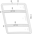
- FIG. 4 illustrates a door panel for a tiltrotor aircraft to which a pair of removable magnetic door handles in accordance with embodiments described herein are connected;
- FIG. 5 illustrates a more detailed view of a removeable magnetic door handle in accordance with embodiments described herein;
- FIGS. 6 A and 6 B illustrate operation of the removable magnetic door handle of FIG. 5 ;
- FIG. 7 illustrates a more detailed view of a connection mechanism for connecting a top end of the removable magnetic door handle of FIG. 5 to the door panel.
- forward may refer to a spatial direction that is closer to a front of an aircraft relative to another component or component aspect(s).
- aft may refer to a spatial direction that is closer to a rear of an aircraft relative to another component or component aspect(s).
- inboard may refer to a location of a component that is within the fuselage of an aircraft and/or a spatial direction that is closer to or along a centerline of the aircraft (wherein the centerline runs between the front and the rear of the aircraft) or other point of reference relative to another component or component aspect.
- outboard may refer to a location of a component that is outside the fuselage of an aircraft and/or a spatial direction that farther from the centerline of the aircraft or other point of reference relative to another component or component aspect.
- the removable magnetic door handle for selectively connecting to a door or access panel (hereinafter collectively referred to as a “door”) of an aircraft, for example.
- the removable magnetic door handle includes self-locating rare earth magnets that assist in pulling handle into its installed position and locking the handle into place.
- the magnets pull the handle into a location that includes a keyed slot to further lock the handle into place to withstand door removal handling loads or wind gust loads and prevent handle rotation. No fasteners or alignment efforts are needed, resulting in reduced installation/removal time, as well as reduced labor costs.
- the design is scalable, modular, and may be used for any door or access panel hold requirements, as well as operations and maintenance. Handle weight and aerodynamic drag may be eliminated from the aircraft by removing the handle during flight and attaching it when the door or access panel needs to be removed.
- FIGS. 1 and 2 illustrate an example tiltrotor aircraft 101 that includes ducted rotors (or fans).
- the tiltrotor aircraft 101 is convertible between a helicopter mode (shown in FIG. 1 ), which allows for vertical takeoff and landing, hovering, and low speed directional movement, and an airplane mode (shown in FIG. 2 ), which allows for forward flight as well as horizontal takeoff and landing.
- Aircraft 101 comprises a fuselage 103 with a fixed wing 105 that extends therefrom and a plurality of rotatable ducts 107 .
- Each duct 107 houses a power plant for driving an attached rotor 109 in rotation.
- Each rotor 109 has a plurality of blades 111 configured to rotate within ducts 107 .
- aircraft 101 is configured with four ducts 107 , including two ducts 107 a and 107 b that form a forward pair of ducts and two ducts 107 c and 107 d that form an aft pair of ducts.
- Each duct 107 is rotatably coupled to fuselage 103 of aircraft 101 via a spindle.
- Ducts 107 a and 107 b are coupled directly to fuselage 103 by a respective spindle 113 .
- Ducts 107 c and 107 d are each independently coupled to a corresponding end of wing 105 via a respective spindle 115 .
- each of ducts 107 c and 107 d includes a winglet 117 that is coupled thereto. It should be appreciated that aircraft 101 is not limited to the illustrated configuration having four ducts 107 , and that aircraft 101 may alternatively be implemented with more or fewer ducts 107 .
- ducts 107 can be selectively controlled to control direction, thrust, and lift of rotors 109 .
- ducts 107 are repositionable to convert aircraft 101 between a helicopter mode and an airplane mode.
- ducts 107 are positioned such that aircraft 101 is in helicopter mode, which allows for vertical takeoff and landing, hovering, and low-speed directional movement.
- ducts 107 are positioned such that aircraft 101 is in airplane mode, which allows for high-speed forward-flight.
- ducts 107 direct their respective thrusts in the aft direction to propel aircraft 101 .
- Aircraft 101 is operable to fly in all directions during the vertical takeoff and landing (i.e., helicopter) mode configuration of FIG. 1 , although faster forward flight is achievable while in the forward flight (i.e., airplane) mode configuration of FIG. 2 .
- Ducted fans 107 may be tiltable between the vertical and horizontal positions by spindles 113 , 115 , which are rotatable in response to commands originating from a pilot and/or a flight control system of the aircraft 101 .
- FIG. 3 illustrates the fuselage 103 of the aircraft 101 so that a door, or access panel, 300 is more clearly visible.
- door 300 covers an opening in skin 302 of the fuselage 103 ; therefore, removing the door 300 provides access to the opening and thus into the fuselage.
- aircraft 101 may be provided with additional doors for accessing areas of the aircraft internal to the fuselage 103 , for example.
- door 300 is provided with removable magnetic door handles 304 embodying features that will be described in greater detail hereinbelow.
- FIG. 4 is a more detailed view of the door 300 with the handles 304 attached.
- door 300 includes channels 400 (in particular, C-channels) in which handles 304 are attached and/or secured, as will be described in greater detail below.
- Channels 400 may be made from aluminum and may be standard extrusions or machined parts.
- channels comprise a support structure for the door panel for providing additional stiffness.
- handles 304 are useful and/or necessary for removing the door 300 from the fuselage 103 and returning the door to the fuselage, during flight of the aircraft 101 , the handles increase the weight of the aircraft and result in aerodynamic drag. Therefore, the fact that handles 304 may be selectively securely attached to the door 300 when needed and easily removed from the door 300 when not in use and/or when the aircraft 101 is in flight is highly beneficial.
- FIG. 5 is a more detailed view of a removable magnetic door handle 500 (which may be used to implement handles 304 ) connected to a door 502 (which may correspond to door 300 ) in accordance with features of embodiments described herein.
- removable magnetic door handle 500 comprises an elongated grip portion 504 that may be grasped by a user during removal and/or installation of the door 502 in connection with an aircraft.
- features 506 comprising indentations may be provided on an interior face of grip portion 504 for accommodating the user's fingers, rendering the grip portion 504 easier and more comfortable to grasp.
- Flanges 508 are disposed on opposite ends of grip portion 504 and extend substantially perpendicular to and form approximately 90 degree angles with the grip portion such that the handle 500 has a roughly C-shaped profile.
- handle supports 510 are provided and are recessed within a channel 512 provided in an external face of the door 502 .
- the channel 512 may be covered by a skin 513 of the door 502 (or a separate skin), with openings 514 in the skin provided for receiving flanges 508 .
- supports 510 comprise C-channels portions including a web 516 and flanges 518 .
- Flanges 518 engage side walls of the channel 512 .
- dimensions (e.g., depth and width) of the channel 512 are sufficient to accommodate corresponding dimensions of the supports 510 .
- Supports 510 may be made from aluminum and may be fastened to or integrated with channels 400 .
- distal ends of upper faces of flanges 508 engage with bottom faces of supports 510 and are maintained in contact and appropriate alignment with one another via magnetic and mechanical forces.
- magnets 600 are disposed on or in flanges 508 .
- the magnets 600 may be recessed into flanges 508 and exposed through upper faces thereof.
- magnets 600 are implemented as rare earth magnets, which are strong permanent magnets made from alloys of rare-earth elements. Rare-earth magnets are the strongest type of permanent magnets currently available, producing magnetic fields in excess of 1.4 teslas, whereas ferrite or ceramic magnets typically exhibit fields of 0.5 to 1 tesla.
- top faces of flanges 508 may be provided with locking features 602 disposed proximate distal ends thereof.
- locking features 602 may be implemented as tabs or protrusions projecting from top faces of flanges 508 for engaging with slots 604 disposed in bottom faces of webs 516 of supports 510 .
- Slots 604 may be disposed only partially through webs 516 or may be cut all the way through webs 516 .
- one of the features 602 and the corresponding slot 604 comprise a “keyed slot.”
- supports 510 are also provided with magnets 700 , which may be recessed into and exposed on bottom faces of webs 516 .
- the magnets 700 comprise rare earth magnets.
- corresponding pairs of magnets 600 , 700 exhibit sufficient attractive force upon one another to draw the upper faces of the flanges 508 toward the bottom faces of the webs 516 , as indicated by arrows 702 , pulling the locking features 606 into the slots 604 to ensure proper alignment of the handle 500 within the channel 512 , and to maintain the handle in secure connection with the door 502 until the handle is manually removed; that is, until manual force sufficient to overcome the magnetic attraction is exerted on the handle in a direction indicated by an arrow 704 .
- the orientation of the handle installation with door is such that gravity, the locking feature and magnets all work together in unison to eliminate the need for fasteners.
- engagement of locking features 602 within slots 604 prevent the handle 500 from being disengaged from the door 502 merely by applying force in a direction perpendicular to the face of the door (i.e., pulling the handle out) or rotation of the handle relative to the door. Allowing rotation of the handle relative to the door would reduce control of handling the door and cause persons hand to be pinched between door and handle. It is anticipated that other types of locking mechanisms including a protrusion and appropriately shaped receptacle for preventing such disengagement of the handle 500 from the door 502 may additionally and/or alternatively be provided for performing the same function.
- aircraft illustrated herein such as aircraft 101
- aircraft is merely illustrative of a variety of aircraft that can implement the embodiments disclosed herein.
- the various embodiments described herein may be used on any aircraft that utilizes motors.
- Other aircraft implementations can include hybrid aircraft, tiltrotor aircraft, quad tiltrotor aircraft, unmanned aircraft, gyrocopters, airplanes, helicopters, commuter aircraft, fixed wing aircraft, electric aircraft, hybrid-electric aircraft, ducted fan aircraft having any number of ducted fans, tiltwing aircraft, including tiltwing aircraft having one or more interwing linkages, more or fewer ducted fans or non-ducted rotors and the like.
- ducted fan aircraft having any number of ducted fans, tiltwing aircraft, including tiltwing aircraft having one or more interwing linkages, more or fewer ducted fans or non-ducted rotors and the like.
- the embodiments described herein can be integrated into a variety of aircraft configurations. It should be appreciated that even though aircraft are particularly well-suited to implement the embodiments of the present disclosure, non
- Example 1 is a handle assembly for an access panel including a support structure including upper and lower supports attached to the access panel, each of the upper and lower supports comprising a top face and a bottom face; a handle for selectively engaging with the support structure, the handle comprising a grip portion and upper and lower flanges extending perpendicularly from the grip portion, each of the upper and lower flanges comprising a top face; and a retention mechanism for retaining the handle in contact with the support structure with a combination of magnetic and mechanical force.
- the handle assembly of Example 1 may further include the retention mechanism comprising a pair of magnets and a keyed slot.
- Example 3 the handle assembly of any of Examples 1 and 2 may further include each of the magnets comprising a rare earth magnet.
- Example 4 the handle assembly of any of Examples 1-3 may further include a first magnet of the pair of magnets being disposed in the top face of the upper flange and wherein a second magnet of the pair of magnets being disposed in the bottom face of the upper support.
- Example 5 the handle assembly of any of Examples 1-4 may further include the keyed slot comprising a protrusion in one of the top face of the upper flange and the bottom face of the upper support and a corresponding slot for receiving and retaining the protrusion disposed in the other one of the top face of the upper flange and the bottom face of the upper support.
- Example 6 the handle assembly of any of Examples 1-5 may further include the retention mechanism comprising a first retention mechanism for retaining the top face of the upper flange in contact with the bottom face of the upper support and a second retention mechanism for retaining the top face of the lower flange in contact with the bottom face of the lower flange.
- Example 7 the handle assembly of any of Examples 1-6 may further include the retention mechanism inhibiting movement of the handle in a direction normal to a plane of the access panel.
- Example 8 the handle assembly of any of Examples 1-7 may further include the retention mechanism inhibiting movement of the handle in a downward direction absent application of a predetermined force.
- Example 9 is an access panel including at least one handle assembly connected to the access panel, the at least one handle assembly comprising a support structure including upper and lower supports attached to the access panel, each of the upper and lower supports comprising a top face and a bottom face; a handle for selectively engaging with the support structure, the handle comprising a grip portion and upper and lower flanges extending perpendicularly from the grip portion, each of the upper and lower flanges comprising a top face; and a retention mechanism comprising a pair of magnets and a keyed slot for retaining the handle in contact with the support structure.
- the access panel of Example 9 may further include each of the magnets comprising a rare earth magnet.
- Example 11 the access panel of any of Examples 9-10 may further include a first magnet of the pair of magnets being disposed in the top face of the upper flange and a second magnet of the pair of magnets being disposed in the bottom face of the upper support.
- Example 12 the access panel of any of Examples 9-11 may further include the keyed slot comprising a protrusion in one of the top face of the upper flange and the bottom face of the upper support and a corresponding slot for receiving and retaining the protrusion disposed in the other one of the top face of the upper flange and the bottom face of the upper support.
- Example 13 the access panel of any of Examples 9-12 may further include the retention mechanism comprising a first retention mechanism for retaining the top face of the upper flange in contact with the bottom face of the upper support and a second retention mechanism for retaining the top face of the lower flange in contact with the bottom face of the lower flange.
- Example 14 the access panel of any of Examples 9-13 may further include the keyed slot inhibiting movement of the handle in a direction normal to a plane of the access panel.
- Example 15 the access panel of any of Examples 9-14 may further include the pair of magnets inhibiting movement of the handle in a downward direction absent application of a predetermined force.
- Example 16 is an aircraft comprising an access panel; at least one handle assembly connected to the access panel, the at least one handle assembly comprising a support structure including upper and lower supports attached to the access panel, each of the upper and lower supports comprising a top face and a bottom face; a handle for selectively engaging with the support structure, the handle comprising a grip portion and upper and lower flanges extending perpendicularly from the grip portion, each of the upper and lower flanges comprising a top face; and a retention mechanism comprising a pair of magnets and a keyed slot for retaining the handle in contact with the support structure.
- Example 17 the aircraft of Example 16 may further include each of the magnets comprising a rare earth magnet and a first magnet of the pair of magnets being disposed in the top face of the upper flange and wherein a second magnet of the pair of magnets being disposed in the bottom face of the upper support.
- Example 18 the aircraft of any of Examples 16-17 may further include the keyed slot comprising a protrusion in one of the top face of the upper flange and the bottom face of the upper support and a corresponding slot for receiving and retaining the protrusion disposed in the other one of the top face of the upper flange and the bottom face of the upper support.
- Example 19 the aircraft of any of Examples 16-18 may further include the retention mechanism comprising a first retention mechanism for retaining the top face of the upper flange in contact with the bottom face of the upper support and a second retention mechanism for retaining the top face of the lower flange in contact with the bottom face of the lower flange.
- Example 20 the aircraft of any of Examples 16-19 may further include the keyed slot inhibiting movement of the handle in a direction normal to a plane of the access panel and the pair of magnets inhibiting movement of the handle in a downward direction absent application of a predetermined force.
- R Rl+k*(Ru ⁇ Rl)
- k is a variable ranging from 1 percent to 100 percent with a 1 percent increment, i.e., k is 1 percent, 2 percent, 3 percent, 4 percent, 5 percent, . . . 50 percent, 51 percent, 52 percent, . . . , 95 percent, 96 percent, 95 percent, 98 percent, 99 percent, or 100 percent.
- any numerical range defined by two R numbers as defined in the above is also specifically disclosed.
- certain embodiments may be implemented using more, less, and/or other components than those described herein.
- some components may be implemented separately, consolidated into one or more integrated components, and/or omitted.
- methods associated with certain embodiments may be implemented using more, less, and/or other steps than those described herein, and their steps may be performed in any suitable order.
- each of the expressions “at least one of X, Y and Z”, “at least one of X, Y or Z”, “one or more of X, Y and Z”, “one or more of X, Y or Z” and “A, B and/or C” can mean any of the following: 1) X, but not Y and not Z; 2) Y, but not X and not Z; 3) Z, but not X and not Y; 4) X and Y, but not Z; 5) X and Z, but not Y; 6) Y and Z, but not X; or 7) X, Y, and Z.
- first”, “second”, “third”, etc. are intended to distinguish the particular nouns (e.g., blade, rotor, element, device, condition, module, activity, operation, etc.) they modify. Unless expressly stated to the contrary, the use of these terms is not intended to indicate any type of order, rank, importance, temporal sequence, or hierarchy of the modified noun.
- first X and “second X” are intended to designate two X elements that are not necessarily limited by any order, rank, importance, temporal sequence, or hierarchy of the two elements.
- “at least one of”, “one or more of”, and the like can be represented using the “(s)” nomenclature (e.g., one or more element(s)).
Landscapes
- Engineering & Computer Science (AREA)
- Mechanical Engineering (AREA)
- Aviation & Aerospace Engineering (AREA)
- Aiming, Guidance, Guns With A Light Source, Armor, Camouflage, And Targets (AREA)
Abstract
Description
Claims (16)
Applications Claiming Priority (3)
| Application Number | Priority Date | Filing Date | Title |
|---|---|---|---|
| ININ202021021432 | 2020-05-21 | ||
| IN202021021432 | 2020-05-21 | ||
| IN202021021432 | 2020-05-21 |
Publications (2)
| Publication Number | Publication Date |
|---|---|
| US20210363780A1 US20210363780A1 (en) | 2021-11-25 |
| US11719018B2 true US11719018B2 (en) | 2023-08-08 |
Family
ID=78607822
Family Applications (1)
| Application Number | Title | Priority Date | Filing Date |
|---|---|---|---|
| US16/915,377 Active 2041-10-19 US11719018B2 (en) | 2020-05-21 | 2020-06-29 | Removable magnetic door handle |
Country Status (1)
| Country | Link |
|---|---|
| US (1) | US11719018B2 (en) |
Cited By (2)
| Publication number | Priority date | Publication date | Assignee | Title |
|---|---|---|---|---|
| US20210363781A1 (en) * | 2020-05-21 | 2021-11-25 | Bell Textron Inc. | Two position door handle with push-push mechanism |
| US11840861B1 (en) * | 2022-05-02 | 2023-12-12 | Theresa Harper | Selectively securable, magnetically attachable and removable, foot activated doorway opener, preferably for horizontally sliding screen doors |
Families Citing this family (3)
| Publication number | Priority date | Publication date | Assignee | Title |
|---|---|---|---|---|
| US11821235B2 (en) * | 2020-05-21 | 2023-11-21 | Textron Innovations Inc | Integrated door handle with hinged access cover |
| US20250052480A1 (en) * | 2023-07-10 | 2025-02-13 | Hisense USA Corporation | Refrigerator door handle |
| USD1040640S1 (en) * | 2024-05-12 | 2024-09-03 | Shenzhen City Qianhai Shengda Industrial Co., Ltd | Magnetic screen door reinforcement |
Citations (5)
| Publication number | Priority date | Publication date | Assignee | Title |
|---|---|---|---|---|
| US3484894A (en) * | 1967-12-15 | 1969-12-23 | Ltv Electrosystems Inc | Removable handle |
| US5887927A (en) * | 1997-10-01 | 1999-03-30 | Southco, Inc. | Folding handle device |
| US8567430B2 (en) * | 2009-10-30 | 2013-10-29 | Masco Corporation Of Indiana | Magnetic coupling for faucet handle |
| US20170283030A1 (en) * | 2016-04-01 | 2017-10-05 | Textron Aviation Inc. | Entry handle |
| US20200190847A1 (en) * | 2016-11-11 | 2020-06-18 | Pure Hold Limited | Self-cleaning door handle cover |
-
2020
- 2020-06-29 US US16/915,377 patent/US11719018B2/en active Active
Patent Citations (5)
| Publication number | Priority date | Publication date | Assignee | Title |
|---|---|---|---|---|
| US3484894A (en) * | 1967-12-15 | 1969-12-23 | Ltv Electrosystems Inc | Removable handle |
| US5887927A (en) * | 1997-10-01 | 1999-03-30 | Southco, Inc. | Folding handle device |
| US8567430B2 (en) * | 2009-10-30 | 2013-10-29 | Masco Corporation Of Indiana | Magnetic coupling for faucet handle |
| US20170283030A1 (en) * | 2016-04-01 | 2017-10-05 | Textron Aviation Inc. | Entry handle |
| US20200190847A1 (en) * | 2016-11-11 | 2020-06-18 | Pure Hold Limited | Self-cleaning door handle cover |
Cited By (3)
| Publication number | Priority date | Publication date | Assignee | Title |
|---|---|---|---|---|
| US20210363781A1 (en) * | 2020-05-21 | 2021-11-25 | Bell Textron Inc. | Two position door handle with push-push mechanism |
| US11976496B2 (en) * | 2020-05-21 | 2024-05-07 | Textron Innovations Inc. | Two position door handle with push-push mechanism |
| US11840861B1 (en) * | 2022-05-02 | 2023-12-12 | Theresa Harper | Selectively securable, magnetically attachable and removable, foot activated doorway opener, preferably for horizontally sliding screen doors |
Also Published As
| Publication number | Publication date |
|---|---|
| US20210363780A1 (en) | 2021-11-25 |
Similar Documents
| Publication | Publication Date | Title |
|---|---|---|
| US11719018B2 (en) | Removable magnetic door handle | |
| US20220274715A1 (en) | Aircraft rotor assembly with segmented input shaft for electric motor stack and gearbox unit | |
| EP3702276B1 (en) | A multirotor joined-wing aircraft with vtol capabilities | |
| CN109665094B (en) | Multi-rotor aircraft with fuselage and at least one wing | |
| US11220852B2 (en) | Aircraft having versatile door systems | |
| KR20200063073A (en) | A vertical take-off and landing multirotor aircraft with at least eight thrust producing units | |
| US12084173B2 (en) | Rotor alignment tab | |
| CA3050051C (en) | A compound helicopter with a fixed wing arrangement | |
| EP3929089A1 (en) | Electric motor stack with integral one-piece gearbox input shaft | |
| US20220324558A1 (en) | Tilting hexrotor aircraft | |
| KR20130026506A (en) | Personal aircraft | |
| US12234011B2 (en) | Convertiplane with stopped rotors, and repositionable rotor blades | |
| US11827344B2 (en) | Low noise ducted fan | |
| US11976496B2 (en) | Two position door handle with push-push mechanism | |
| US11634233B2 (en) | Distributed battery bank for ducted-rotor aircraft | |
| US11519196B2 (en) | Utility door handle assembly | |
| US11591081B2 (en) | Vertical-lift augmentation system | |
| US11821235B2 (en) | Integrated door handle with hinged access cover | |
| US12240597B2 (en) | Aircraft with wing having integrated ducted fans | |
| US11772804B2 (en) | Electric tiltrotor aircraft with offset tilting motors | |
| US11685502B2 (en) | Modular hybrid airframe structure for battery thermal event protection and repair | |
| US11565799B2 (en) | Adjustable ducted rotor blade tip extension | |
| US20210403149A1 (en) | Rotor system with reconfigurable duct | |
| US11745867B2 (en) | Pylon conversion actuator for tiltrotor aircraft | |
| JP2026505834A (en) | Aircraft with flow guidance structure and flow guidance system |
Legal Events
| Date | Code | Title | Description |
|---|---|---|---|
| AS | Assignment |
Owner name: BELL TEXTRON INC., TEXAS Free format text: ASSIGNMENT OF ASSIGNORS INTEREST;ASSIGNORS:AMANTE, WILLIAM ANTHONY;KOPPA SIDDALINGAPPA, ARUNKUMAR;BANSAL, DARPAN;SIGNING DATES FROM 20200620 TO 20200622;REEL/FRAME:053076/0728 |
|
| FEPP | Fee payment procedure |
Free format text: ENTITY STATUS SET TO UNDISCOUNTED (ORIGINAL EVENT CODE: BIG.); ENTITY STATUS OF PATENT OWNER: LARGE ENTITY |
|
| AS | Assignment |
Owner name: TEXTRON INNOVATIONS INC., RHODE ISLAND Free format text: ASSIGNMENT OF ASSIGNORS INTEREST;ASSIGNOR:BELL TEXTRON RHODE ISLAND INC.;REEL/FRAME:057732/0430 Effective date: 20210101 Owner name: BELL TEXTRON RHODE ISLAND INC., RHODE ISLAND Free format text: ASSIGNMENT OF ASSIGNORS INTEREST;ASSIGNOR:BELL TEXTRON INC.;REEL/FRAME:057732/0340 Effective date: 20210101 |
|
| STPP | Information on status: patent application and granting procedure in general |
Free format text: NON FINAL ACTION MAILED |
|
| STPP | Information on status: patent application and granting procedure in general |
Free format text: PUBLICATIONS -- ISSUE FEE PAYMENT VERIFIED |
|
| STCF | Information on status: patent grant |
Free format text: PATENTED CASE |