US11718402B2 - Systems and methods for a thrust-vector controlled hybrid unmanned aerial and ground vehicle with improved grasping - Google Patents
Systems and methods for a thrust-vector controlled hybrid unmanned aerial and ground vehicle with improved grasping Download PDFInfo
- Publication number
- US11718402B2 US11718402B2 US17/335,968 US202117335968A US11718402B2 US 11718402 B2 US11718402 B2 US 11718402B2 US 202117335968 A US202117335968 A US 202117335968A US 11718402 B2 US11718402 B2 US 11718402B2
- Authority
- US
- United States
- Prior art keywords
- vehicle
- propeller
- deflector
- optimal
- angle
- Prior art date
- Legal status (The legal status is an assumption and is not a legal conclusion. Google has not performed a legal analysis and makes no representation as to the accuracy of the status listed.)
- Active, expires
Links
Images


Classifications
-
- B—PERFORMING OPERATIONS; TRANSPORTING
- B64—AIRCRAFT; AVIATION; COSMONAUTICS
- B64C—AEROPLANES; HELICOPTERS
- B64C39/00—Aircraft not otherwise provided for
- B64C39/02—Aircraft not otherwise provided for characterised by special use
- B64C39/024—Aircraft not otherwise provided for characterised by special use of the remote controlled vehicle type, i.e. RPV
-
- B—PERFORMING OPERATIONS; TRANSPORTING
- B64—AIRCRAFT; AVIATION; COSMONAUTICS
- B64C—AEROPLANES; HELICOPTERS
- B64C13/00—Control systems or transmitting systems for actuating flying-control surfaces, lift-increasing flaps, air brakes, or spoilers
- B64C13/02—Initiating means
- B64C13/16—Initiating means actuated automatically, e.g. responsive to gust detectors
-
- B—PERFORMING OPERATIONS; TRANSPORTING
- B64—AIRCRAFT; AVIATION; COSMONAUTICS
- B64C—AEROPLANES; HELICOPTERS
- B64C37/00—Convertible aircraft
-
- B—PERFORMING OPERATIONS; TRANSPORTING
- B64—AIRCRAFT; AVIATION; COSMONAUTICS
- B64C—AEROPLANES; HELICOPTERS
- B64C9/00—Adjustable control surfaces or members, e.g. rudders
- B64C9/08—Adjustable control surfaces or members, e.g. rudders bodily displaceable
-
- B—PERFORMING OPERATIONS; TRANSPORTING
- B64—AIRCRAFT; AVIATION; COSMONAUTICS
- B64U—UNMANNED AERIAL VEHICLES [UAV]; EQUIPMENT THEREFOR
- B64U10/00—Type of UAV
- B64U10/70—Convertible aircraft, e.g. convertible into land vehicles
-
- B—PERFORMING OPERATIONS; TRANSPORTING
- B64—AIRCRAFT; AVIATION; COSMONAUTICS
- B64U—UNMANNED AERIAL VEHICLES [UAV]; EQUIPMENT THEREFOR
- B64U50/00—Propulsion; Power supply
- B64U50/10—Propulsion
- B64U50/18—Thrust vectoring
-
- B—PERFORMING OPERATIONS; TRANSPORTING
- B64—AIRCRAFT; AVIATION; COSMONAUTICS
- B64U—UNMANNED AERIAL VEHICLES [UAV]; EQUIPMENT THEREFOR
- B64U10/00—Type of UAV
- B64U10/10—Rotorcrafts
- B64U10/13—Flying platforms
-
- B—PERFORMING OPERATIONS; TRANSPORTING
- B64—AIRCRAFT; AVIATION; COSMONAUTICS
- B64U—UNMANNED AERIAL VEHICLES [UAV]; EQUIPMENT THEREFOR
- B64U10/00—Type of UAV
- B64U10/10—Rotorcrafts
- B64U10/13—Flying platforms
- B64U10/14—Flying platforms with four distinct rotor axes, e.g. quadcopters
-
- B—PERFORMING OPERATIONS; TRANSPORTING
- B64—AIRCRAFT; AVIATION; COSMONAUTICS
- B64U—UNMANNED AERIAL VEHICLES [UAV]; EQUIPMENT THEREFOR
- B64U2201/00—UAVs characterised by their flight controls
- B64U2201/10—UAVs characterised by their flight controls autonomous, i.e. by navigating independently from ground or air stations, e.g. by using inertial navigation systems [INS]
Definitions
- the present disclosure generally relates to unmanned aerial and ground vehicles (UAGVs), and in particular, to improved control and maneuverability for UAGVs using thrust-vector control.
- UAGVs unmanned aerial and ground vehicles
- Multicopters are becoming popular for various tasks such as pick-and-place and contaminant collection. In a variety of these tasks, interactions with the environment or humans are an inevitable aspect of the task. To enable aerial grasping/manipulation, multicopters are equipped with rigid or soft graspers. However, aerial grasping/manipulation is a challenging task as it requires extremely precise real-time position control which is almost impossible due to ground effect. Especially in outdoor environments, extremely precise motion sensors are not available. For example, GPS sensors are predominantly utilized outdoors for position estimation. Although these sensors are cheap and are a good source of localization in the world frame, they are not accurate enough to perform critical tasks like aerial grasping and manipulation.
- FIG. 1 is a photograph showing a thrust vector-controlled unmanned aerial and ground vehicle having a plurality of deflectors, a plurality of propellers, and a grasper;
- FIG. 2 is a photograph showing a side view of the vehicle of FIG. 1 illustrating locations of various electronic components
- FIG. 3 is an illustration showing actuation hardware for the vehicle of FIG. 1 ;
- FIG. 4 A is an illustration showing net upward force on the body of the vehicle of FIG. 1 produced by a single propeller
- FIG. 4 B is an illustration showing net vertical force on the body of the vehicle of FIG. 1 produced by a single propeller
- FIGS. 5 A- 5 C are a series of block diagrams showing a controller for the vehicle of FIG. 1 and associated electronic components;
- FIG. 6 is a photograph showing the vehicle of FIG. 1 traveling on the ground and approaching an object
- FIGS. 7 A and 7 B are sequential photographs of the vehicle of FIG. 1 respectively showing the grasper surrounding and gripping an object;
- FIG. 8 is a graphical representation showing pulse width modulation (PWM) with respect to thrust of the vehicle of FIG. 1 following experimental testing;
- FIGS. 9 A- 9 C are a series of graphical representations showing airflow being directed by the plurality of propellers around the plurality of deflectors, each deflector being strategically angled to direct airflow around the vehicle of FIG. 1 ;
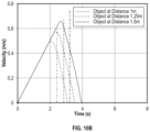
- FIG. 10 A- 10 D are a series of graphical representations showing state trajectories with NMPC and control signals with respect to error;
- FIG. 11 is a graphical representation showing a relation between contour area and distance for the camera
- FIG. 12 is a graphical representation showing NMPC control performance for an object placed at different initial conditions for a total of 45 trials.
- FIG. 13 is a diagram showing an example computing system for implementation of the controller of FIG. 5 A- 5 C .
- the vehicle defines a body and a plurality of arms extending from a center of the body.
- Each of the plurality of arms includes a respective rotatable propeller and a deflector located underneath the propeller.
- Each deflector is operable for controlled upward or downward rotation relative to a direction of elongation of the arm (i.e. raised or lowered, respectively) to redirect airflow underneath and around the vehicle as the propeller rotates.
- each deflector may be individually raised or lowered such that airflow can be precisely controlled for improved maneuverability of the vehicle through air.
- the vehicle includes a forward-facing grasper and a plurality of passive wheels integrated with the body for maneuvering on a ground surface.
- the vehicle can land in front of an object and drive in a horizontal direction along the ground using the propellers and the deflectors to pick the object up using the forward-facing grasper.
- the vehicle further communicates with a controller module that uses sensor feedback to determine vehicle control parameters including those that control the deflectors. Referring to the drawings, embodiments of a thrust vector-controlled UAG vehicle are illustrated and generally indicated as 100 in FIGS. 1 - 13 .
- the thrust vector-controlled unmanned aerial and ground vehicle (UAGV) or “the vehicle” 100 is shown defining a body 102 and a plurality of arms 108 .
- the plurality of arms 108 extend radially from the body 102 of the vehicle 100 .
- Each of the plurality of arms 108 includes a propeller 116 and an associated deflector 106 , the deflector 106 being a planar surface.
- Each propeller 116 is rotatable by an associated propeller motor 122 , either individually or collectively.
- Each deflector 106 is pivotable about a deflector pivot axis n y by an actuator assembly 160 .
- the deflectors 106 allow for improved steering and control of the vehicle 100 by performing thrust-vectoring with airflow generated by the propeller 116 .
- the vehicle 100 further includes a plurality of wheels 114 located on the first and opposite second sides of the body 102 .
- the wheels 114 are passively rotatable for landing on the ground.
- the vehicle 100 further includes a grasper 110 located on the body 102 for grabbing or otherwise manipulating objects.
- the present vehicle 100 can operate in an “airborne mode” or a “ground mode” and is thus not constrained to performing precise landings on an object but can land away from the object and attempt grasping while moving on a ground surface in a “ground mode”.
- this vehicle 100 can also be investigated for improved aerial agility.
- the vehicle 100 communicates with a controller 104 for control of various electronic components of the vehicle 100 and for determining vehicle control parameters based on sensor feedback.
- the controller 104 is located onboard the vehicle 100 .
- each propeller 116 generates airflow which is re-directed by a respective deflector 106 of the plurality of deflectors 106 .
- Each deflector 106 is pivotable about its respective deflector pivot axis n y .
- the deflector pivot axis n y is perpendicular to the direction of elongation of the respective arm 108 ( FIG. 1 ).
- the pivoting of each deflector 106 is individually controlled by a respective actuator assembly 160 .
- These actuators 164 can operate in response to input from the controller 104 .
- the actuators 164 can be connected to the deflectors 106 using push rods 163 .
- Each push rod 163 is coupled to the actuator 164 and the deflector 106 such that as the actuator 164 rotates in a first direction, the push rod 163 increases an angle of the deflector 106 relative to the vertical axis and as the actuator 164 rotates in an opposite second direction, the push rod 163 decreases an angle of the deflector 106 relative to the vertical axis.
- a deflector angle u 2 is increased or decreased to divert the vertical airflow from the propellers 116 .
- the vertical thrust generated by the propellers 116 is deflected to produce horizontal thrust for enabling translational motion on the ground.
- the vehicle 100 produces horizontal thrust via thrust vectoring, and for cases where its heading is aligned with the object 10 on a flat surface after it lands, the vehicle 100 uses the propellers 116 , actuated deflectors 106 and the wheels 110 associated with each arm 108 to move the vehicle 100 on the ground.
- the air from the propellers 116 is directed along the deflectors 106 and as the air leaves the deflector 106 a force is generated on the rigid body in the opposite direction based on Newton's third law. This is exploited to achieve on-surface mobility of the vehicle 100 .
- the deflectors 106 are laser-cut acrylic plates mounted directly below the propeller motors 122 and orthogonal to the frame arms 108 .
- the deflectors 106 can rotate about an axis below the propeller motors 122 to generate horizontal forces of different magnitudes.
- the deflectors 106 are 29 cm wide and 15 cm tall to maximize the captured airflow, and therefore maximize the force they generate.
- the controller 104 uses sensor feedback to determine an ideal deflector angle u 2 and an ideal propeller speed ⁇ for the vehicle 100 when in ground mode.
- the sensor is a camera 130 and can determine a position x of a target object 10 relative to the vehicle 100 .
- the controller 104 includes a trajectory planning module 200 that applies a nonlinear predictive control model to the sensor feedback to determine the ideal deflector angle u 2 and an ideal propeller speed ⁇ for the vehicle 100 .
- the trajectory planning module 200 can further include a system model sub-module 216 , a set of input constraints 214 , and a positional error sub-module 212 which are all incorporated into a nonlinear model predictive control (NMPC) sub-module 202 .
- the trajectory planning module 200 iteratively determines an ideal deflector angle u 2 and an ideal propeller speed ⁇ either individually or collectively for each deflector 106 and propeller 116 as the vehicle approaches the object.
- the ideal propeller speed ⁇ as determined at NMPC sub-module 202 of trajectory planning block 200 is converted to a thrust value u 1 which is used along with the deflector angle u 2 as input to control the vehicle 100 .
- Positional feedback is then sent back from the vehicle 100 and incorporated into the controller 104 in an iterative fashion for adaptable control of the vehicle 100 .
- the propeller motors 122 operate in response to the controller 104 to rotate the propellers 116 at an appropriate rotational speed.
- the vehicle 100 can travel on the ground to approach objects 10 in addition to traveling through air.
- the vehicle 100 is equipped with landing gear 168 including a plurality of passive wheels 114 .
- the vehicle 100 further includes the grasper 110 located on the front side of the body 102 .
- the grasper 110 includes a first claw 112 A and a second claw 112 B.
- FIG. 7 A the vehicle 100 is shown approaching an object 10 and in FIG. 7 B the vehicle 100 is shown grasping the object 10 by bringing the first and second claws 112 A and 112 B together.
- grasper 110 is operated by grasper motor 124 . It should be noted that in an alternate embodiment of the vehicle 100 , the grasper 110 may be a different type of tool such as a shovel or a probe.
- the wheels 114 are embodied as continuous track wheels for improved maneuverability on certain types of surfaces.
- the vehicle 100 can include floats (not shown) in lieu of wheels 114 for object collection on water.
- a plurality of sensors can be included onboard the vehicle 100 such as additional cameras, Geiger counters, non-destructive testing (NDT) tools, etc.
- Landing gear 168 aboard the vehicle 100 includes four unpowered, 3D printed legs 169 each associated with a respective wheel 114 so that the vehicle 100 can be restricted to forward or backward motion while on the ground.
- the deflector actuators 164 are fixed onto the landing gear 168 and are attached to the deflectors 106 with push rods so that the deflectors can move between 0° and 45° outwards.
- the actuation assembly 160 can be seen for a single arm 108 of the plurality of arms 108 in FIG. 3 .
- the vehicle includes a camera 130 to detect objects and a standard robotic aluminum grasper 110 to collect objects that the camera 130 detects.
- the grasper 110 is fixed below the body 102 of the vehicle 100 and is front-facing.
- the camera 130 is also front-facing and mounted above the grasper 110 such that the distance between the grasper 110 and camera 130 is minimized.
- the camera 130 is connected to the high-level computer 140 that processes images from the camera 130 and generates control setpoints for the vehicle 100 .
- the grasper 110 is actuated by a grasper motor 124 onboard the vehicle 100 that receives input from the controller 104 to operate the grasper 110 .
- the vehicle 100 uses conventional quadrotor control techniques to fly.
- a ground mode model is implemented by trajectory planning model 200 on the controller 104 for control of the vehicle while on a ground surface.
- This section describes the ground mode model developed using first principles for the actuator assembly 160 and deflectors 106 and also presents the validation through Solid-Works Flow Simulation. The notations frequently used in this disclosure are described in Table. I.
- a front-facing monocular camera 130 is utilized for object detection and tracking.
- Color and edge detection techniques are implemented by an object detection and tracking module 220 utilized for the purpose of object detection and tracking.
- the contour area (A c ) in the camera frame is calculated from different distances ranging from 0.25 m to 1.5 m.
- the camera 130 loses features and the tracking performance deteriorates when the object is within 0.25 m.
- the calculated depth (d) is inaccurate.
- This problem can be resolved by using a tilting camera instead of a fixed camera so that the object is always in the frame.
- MATLAB's curve fitting tool is utilized to obtain a function between contour area and depth.
- the equations representing the model between contour area and depth is as follows:
- FIG. 11 shows the relation between the contour area and the depth at which the tracked object is located.
- the trajectory planning module 200 can be implemented on a high-level computer 140 .
- the computed signals from the trajectory planning module 200 are transmitted serially to a flight control unit 150 .
- the vehicle 100 uses a 1 MP global shutter forward facing camera 130 in communication with an object detection and tracking module 220 for object detection and tracking.
- the camera 130 is connected over USB 2.0 to the high-level computer 140 , however it should be noted that alternative connection protocols can be used including wireless connection (i.e. Bluetooth, Wi-Fi, etc) or a wired connection (i.e. USB-C, micro-USB, etc.).
- One embodiment of the camera 130 outputs 640 ⁇ 480 images at 80 frames per second (FPS).
- the trajectory planning module 200 as well as the object detection and tracking module 220 and a low-level communication module 230 were implemented on the high-level computer 140 .
- the high-level trajectory planning module 200 runs at an update rate of 50 Hz.
- the low-level communication framework was developed using ZeroMQ and Boost ASIO libraries.
- the high-level computer 140 communicates over serial protocol with the flight control unit 150 .
- the control signals are implemented as shown in FIGS. 10 C and 10 D .
- propeller speed pulse width modulation PWM
- ⁇ deflector angle
- u 2 deflector angle
- u 1 total thrust, generated by each propeller 112 for a particular embodiment of vehicle 100
- a custom rig was used to mount the propeller motor 122 and propeller 116 facing into a balancing scale and experimentally find the relationship between ⁇ and u 1 .
- the MATLAB curve fitting toolbox was used to obtain this relationship as given in Eq. (1) and FIG. 8 shows the corresponding plot.
- u 1 - ( ⁇ - 1 ⁇ 6 ⁇ 1 ⁇ 8 2 ⁇ 9 ⁇ 0 ) 3 - 0 , 01249 ⁇ ( ⁇ - 1 ⁇ 6 ⁇ 1 ⁇ 8 2 ⁇ 9 ⁇ 0 ) 2 + 2.885 ⁇ ( ⁇ - 1 ⁇ 618 290 ) + 3.4 ⁇ 1 ⁇ 3 ( 1 )
- ⁇ circumflex over ( ⁇ ) ⁇ x denote an axis parallel to the surface of the deflector 106 at any instant
- ⁇ circumflex over ( ⁇ ) ⁇ y denote the axis about which the deflector 106 rotates as shown in FIGS. 4 A and 4 B .
- each respective deflector 106 ⁇ circumflex over ( ⁇ ) ⁇ y
- the control input u 2 is defined as the angle made by the deflector 106 measured from the ⁇ circumflex over ( ⁇ ) ⁇ z -axis as shown in FIG. 4 A . Since the deflector 106 is mounted below the center of the associated propeller 116 , it captures only half of the total downward airflow and redirects it along ⁇ circumflex over ( ⁇ ) ⁇ x . Assuming that during this process, there is no separation of air flow and air loss, Newton's third law can be applied to calculate the amount of force generated on the vehicle 100 due to this diverted air flow as shown in FIG. 4 A as
- F u 2 ⁇ ( u 1 2 + u 1 2 ⁇ cos ⁇ ⁇ u 2 ) ( 4 )
- F h is in the body X direction.
- F u does not contribute to the forward motion but influences the static friction by decreasing the net reaction force.
- the vehicle 100 needs to overcome static friction before it starts rolling and the static friction for the current system is a function of u 1 and u 2 according to the equation:
- ⁇ s is the coefficient of static friction.
- the model based controller should also account for static friction. This is important to design an optimal control law for the system with two inputs and it is possible that for a particular ⁇ value, there may not exist a feasible u 2 , which will produce a horizontal force, F h , greater than the static friction force and consequently the vehicle 100 will fail to move forward.
- the dynamics of the vehicle 100 are therefore nonlinear with input coupling.
- this section first studies the force generated by one deflector 106 in case (a) and then proceed to validate the net forward force produced by two deflectors 106 in case (b). In both cases, the deflector angles, u 2 , are set to 45°. To simplify the 3D model and reduce computation time, features that do not significantly contribute to the required analysis are first removed. Then, a standard default global mesh is run in the SolidWorks setup. The propeller 112 is modeled as a cylinder since only the outlet velocity of the air leaving the propeller 112 is relevant for the analysis. The arm and wheels on the bottom of the legs are also removed from the simulations as they provide negligible variations of the flow field and reduce the computational time significantly.
- the angle between the deflector 106 and vertical axis is 45°.
- V 0 0 ms ⁇ 1
- A ⁇ D 2 /4
- D 0.22860 m
- Velocity at the top inlet of the propeller 112 is set to 0 ms ⁇ 1 due to stagnant air conditions.
- the resulting output for the velocity exiting the bottom outlet of the propeller 112 is the unknown variable V.
- This theory which is derived from the Bernoulli equation, can be used to determine the relationship between the force output from the propeller 112 and the velocity output of the air flow.
- the determined air velocity beneath the propeller 112 equates to 9 ms- 1 for a 9-inch diameter propeller 112 at standard atmospheric conditions with initial stagnant air velocity of 0 ms- 1 .
- the resultant air velocities below the propellers 112 are used in cases (a) and (b) to find the force produced by the deflectors 106 .
- FIG. 9 C shows the front view of the simulation for two deflectors.
- this section describes the guidance and control in ground mode as implemented by controller 104 , and in particular, as implemented by trajectory planning module 200 .
- the trajectory planning module 200 achieves precise grasping using a variant of explicit nonlinear model predictive control (NMPC) as shown in FIG. 5 A .
- NMPC nonlinear model predictive control
- the vehicle 100 includes or otherwise communicates with the NMPC-based trajectory planning module 200 to find optimal control trajectories for the vehicle based on position, propeller speed, and deflector angle.
- the cost function as implemented with NMPC sub-module 202 of the trajectory planning module 200 is formulated as:
- f(x, u) is given by Eq. (8)
- the cost matrices R and Q are tuned to achieve an over damped response and are set to:
- the trajectory planning module 200 is designed such that with the calculated control sequence, the vehicle arrives at (x obj ⁇ 0.25)m, where x obj denotes the position of the object, with a predetermined velocity such that after it reaches (x obj ⁇ 0.25)m, the control is turned off and the vehicle 100 relies on friction to bring itself to a stop at x obj .
- a prediction horizon T p of the trajectory planning module 200 is set to three samples with a control update rate of 50 Hz.
- the control trajectory is simulated for initial distances of [0.75 1 1.25]m and interpolated for the intermediate values to ensure consistent performance with varying initial distances from the object.
- the interior-point method is used to solve the optimization problem of Eq. (10) and generate the optimal control sequence.
- the control signal generated for different initial distances is shown in FIGS. 10 C and 10 D .
- the black solid line at 0.25 m shows the distance at which the control is turned off and the ⁇ and u 2 values are set to 900 ⁇ s and 30° respectively so that the vehicle 100 slows to a stop.
- FIGS. 10 A and 10 B show the state trajectories during the entire time duration.
- the dotted vertical lines demarcate the points in time after which the propellers 116 are turned off.
- Motion capture data was utilized solely for capturing the performance of the proposed structure and was not used for motion planning or control. The motion capture data was logged at 100 Hz. A polyurethane foam-based carpet was utilized as the surface to prevent sideways sliding movement.
- FIGS. 6 - 7 B show video screenshots for a grasp from the top and side views.
- FIG. 13 illustrates an example of a suitable computing and networking environment (computer system 300 ) which may be used to implement various aspects of the present disclosure.
- Example embodiments described herein may be implemented at least in part in electronic circuitry; in computer hardware executing firmware and/or software instructions; and/or in combinations thereof.
- Example embodiments also may be implemented using a computer program product (e.g., a computer program tangibly or non-transitorily embodied in a machine-readable medium and including instructions for execution by, or to control the operation of, a data processing apparatus, such as, for example, one or more programmable processors or computers).
- a computer program product e.g., a computer program tangibly or non-transitorily embodied in a machine-readable medium and including instructions for execution by, or to control the operation of, a data processing apparatus, such as, for example, one or more programmable processors or computers.
- a computer program may be written in any form of programming language, including compiled or interpreted languages, and may be deployed in any form, including as a stand-alone program or as a subroutine or other unit suitable for use in a computing environment. Also, a computer program can be deployed to be executed on one computer, or to be executed on multiple computers at one site or distributed across multiple sites and interconnected by a communication network.
- modules are hardware-implemented, and thus include at least one tangible unit capable of performing certain operations and may be configured or arranged in a certain manner.
- a hardware-implemented module may comprise dedicated circuitry that is permanently configured (e.g., as a special-purpose processor, such as a field-programmable gate array (FPGA) or an application-specific integrated circuit (ASIC)) to perform certain operations.
- a hardware-implemented module may also comprise programmable circuitry (e.g., as encompassed within a general-purpose processor or other programmable processor) that is temporarily configured by software or firmware to perform certain operations.
- one or more computer systems e.g., a standalone system, a client and/or server computer system, or a peer-to-peer computer system
- one or more processors may be configured by software (e.g., an application or application portion) as a hardware-implemented module that operates to perform certain operations as described herein.
- the term “hardware-implemented module” encompasses a tangible entity, be that an entity that is physically constructed, permanently configured (e.g., hardwired), or temporarily configured (e.g., programmed) to operate in a certain manner and/or to perform certain operations described herein.
- hardware-implemented modules are temporarily configured (e.g., programmed)
- each of the hardware-implemented modules need not be configured or instantiated at any one instance in time.
- the hardware-implemented modules comprise a general-purpose processor configured using software
- the general-purpose processor may be configured as respective different hardware-implemented modules at different times.
- Software in the form of a system application or otherwise, may include a hardware-implemented module and may accordingly configure a processor 302 , for example, to constitute a particular hardware-implemented module at one instance of time and to constitute a different hardware-implemented module at a different instance of time.
- Hardware-implemented modules may provide information to, and/or receive information from, other hardware-implemented modules. Accordingly, the described hardware-implemented modules may be regarded as being communicatively coupled. Where multiple of such hardware-implemented modules exist contemporaneously, communications may be achieved through signal transmission (e.g., over appropriate circuits and buses) that connect the hardware-implemented modules. In embodiments in which multiple hardware-implemented modules are configured or instantiated at different times, communications between such hardware-implemented modules may be achieved, for example, through the storage and retrieval of information in memory structures to which the multiple hardware-implemented modules have access.
- one hardware-implemented module may perform an operation, and may store the output of that operation in a memory device to which it is communicatively coupled. A further hardware-implemented module may then, at a later time, access the memory device to retrieve and process the stored output. Hardware-implemented modules may also initiate communications with input or output devices.
- the computing and networking environment 300 may be a general purpose computing device 300 , although it is contemplated that the networking environment 300 may include other computing systems, such as personal computers, server computers, hand-held or laptop devices, tablet devices, multiprocessor systems, microprocessor-based systems, set top boxes, programmable consumer electronic devices, network PCs, minicomputers, mainframe computers, digital signal processors, state machines, logic circuitries, distributed computing environments that include any of the above computing systems or devices, and the like.
- the networking environment 300 may include other computing systems, such as personal computers, server computers, hand-held or laptop devices, tablet devices, multiprocessor systems, microprocessor-based systems, set top boxes, programmable consumer electronic devices, network PCs, minicomputers, mainframe computers, digital signal processors, state machines, logic circuitries, distributed computing environments that include any of the above computing systems or devices, and the like.
- Components of the general purpose computing device 300 may include various hardware components, such as a processing unit 302 , a main memory 304 (e.g., a memory or a system memory), and a system bus 301 that couples various system components of the general purpose computing device 300 to the processing unit 302 .
- the system bus 301 may be any of several types of bus structures including a memory bus or memory controller, a peripheral bus, and a local bus using any of a variety of bus architectures.
- bus architectures may include Industry Standard Architecture (ISA) bus, Micro Channel Architecture (MCA) bus, Enhanced ISA (EISA) bus, Video Electronics Standards Association (VESA) local bus, and Peripheral Component Interconnect (PCI) bus also known as Mezzanine bus.
- ISA Industry Standard Architecture
- MCA Micro Channel Architecture
- EISA Enhanced ISA
- VESA Video Electronics Standards Association
- PCI Peripheral Component Interconnect
- the general purpose computing device 300 may further include a variety of computer-readable media 307 that includes removable/non-removable media and volatile/nonvolatile media, but excludes transitory propagated signals.
- Computer-readable media 307 may also include computer storage media and communication media.
- Computer storage media includes removable/non-removable media and volatile/nonvolatile media implemented in any method or technology for storage of information, such as computer-readable instructions, data structures, program modules or other data, such as RAM, ROM, EPSOM, flash memory or other memory technology, CD-ROM, digital versatile disks (DVD) or other optical disk storage, magnetic cassettes, magnetic tape, magnetic disk storage or other magnetic storage devices, or any other medium that may be used to store the desired information/data and which may be accessed by the general purpose computing device 300 .
- Communication media includes computer-readable instructions, data structures, program modules, or other data in a modulated data signal such as a carrier wave or other transport mechanism and includes any information delivery media.
- modulated data signal means a signal that has one or more of its characteristics set or changed in such a manner as to encode information in the signal.
- communication media may include wired media such as a wired network or direct-wired connection and wireless media such as acoustic, RF, infrared, and/or other wireless media, or some combination thereof.
- Computer-readable media may be embodied as a computer program product, such as software stored on computer storage media.
- the main memory 304 includes computer storage media in the form of volatile/nonvolatile memory such as read only memory (ROM) and random access memory (RAM).
- ROM read only memory
- RAM random access memory
- BIOS basic input/output system
- RAM typically contains data and/or program modules that are immediately accessible to and/or presently being operated on by processing unit 302 .
- data storage 306 holds an operating system, application programs, and other program modules and program data.
- Data storage 306 may also include other removable/non-removable, volatile/nonvolatile computer storage media.
- data storage 306 may be: a hard disk drive that reads from or writes to non-removable, nonvolatile magnetic media; a magnetic disk drive that reads from or writes to a removable, nonvolatile magnetic disk; and/or an optical disk drive that reads from or writes to a removable, nonvolatile optical disk such as a CD-ROM or other optical media.
- Other removable/non-removable, volatile/nonvolatile computer storage media may include magnetic tape cassettes, flash memory cards, digital versatile disks, digital video tape, solid state RAM, solid state ROM, and the like.
- the drives and their associated computer storage media provide storage of computer-readable instructions, data structures, program modules and other data for the general purpose computing device 300 .
- a user may enter commands and information through a user interface 340 or other input devices 345 such as a tablet, electronic digitizer, a microphone, keyboard, and/or pointing device, commonly referred to as mouse, trackball, or touch pad.
- Other input devices 345 may include a joystick, game pad, satellite dish, scanner, or the like.
- voice inputs, gesture inputs (e.g., via hands or fingers), or other natural user interfaces may also be used with the appropriate input devices, such as a microphone, camera, tablet, touch pad, glove, or other sensor.
- a monitor 360 or other type of display device is also connected to the system bus 301 via user interface 340 , such as a video interface.
- the monitor 360 may also be integrated with a touch-screen panel or the like.
- the general purpose computing device 300 may operate in a networked or cloud-computing environment using logical connections of a network Interface 303 to one or more remote devices, such as a remote computer.
- the remote computer may be a personal computer, a server, a router, a network PC, a peer device or other common network node, and typically includes many or all of the elements described above relative to the general purpose computing device 300 .
- the logical connection may include one or more local area networks (LAN) and one or more wide area networks (WAN), but may also include other networks.
- LAN local area network
- WAN wide area network
- Such networking environments are commonplace in offices, enterprise-wide computer networks, intranets and the Internet.
- the general purpose computing device 300 When used in a networked or cloud-computing environment, the general purpose computing device 300 may be connected to a public and/or private network through the network interface 303 . In such embodiments, a modem or other means for establishing communications over the network is connected to the system bus 301 via the network interface 303 or other appropriate mechanism.
- a wireless networking component including an interface and antenna may be coupled through a suitable device such as an access point or peer computer to a network.
- program modules depicted relative to the general purpose computing device 300 may be stored in the remote memory storage device.
Landscapes
- Engineering & Computer Science (AREA)
- Aviation & Aerospace Engineering (AREA)
- Chemical & Material Sciences (AREA)
- Combustion & Propulsion (AREA)
- Automation & Control Theory (AREA)
- Mechanical Engineering (AREA)
- Remote Sensing (AREA)
- Control Of Position, Course, Altitude, Or Attitude Of Moving Bodies (AREA)
Abstract
Description
| TABLE I |
| NOTATIONS |
| {X, Y, Z} | the body fixed frame with origin at CG of vehicle |
| {{circumflex over (η)}x, {circumflex over (η)}y, {circumflex over (η)}z} | co-ordinate system for each deflector, with its origin |
| at the midpoint of the deflector's top edge | |
| M ϵ | mass of UAGV |
| u1 ϵ | thrust produced by each rotor |
| u2 ϵ [0, 45°] | angle made by the deflector with |
| σ ϵ | rotor PWM |
| Fdef ϵ | force on deflector |
| Fh | component of Fdef in body X-Y plane |
| Fu ϵ | total upward force during ground locomotion in Z axis |
| Fh ϵ | total forward force during ground locomotion in X axis |
A. Camera Setup
F h
where Fh is in the body X direction. Fu does not contribute to the forward motion but influences the static friction by decreasing the net reaction force.
F fric=−μr(Mg−F u) (6)
Thrust=
[x ref v ref]T [x ref v ref]T=[(x obj−0.25)0.42]T
| TABLE II |
| MEAN AND STANDARD DEVIATION OF FINAL |
| DISTANCE BETWEEN THE OBJECT AND UAGV |
| (15 TRIALS FOR EACH CASE) |
| Standard | ||||
| Initial | Mean | Deviation | ||
| 1 m | −0.0609 m | 0.0366 m | ||
| 1.25 m | 0.0370 m | 0.0202 m | ||
| 1.5 m | 0.0462 m | 0.0273 m | ||
Each initial condition has the
Computer-Implemented System
Claims (20)
Priority Applications (1)
| Application Number | Priority Date | Filing Date | Title |
|---|---|---|---|
| US17/335,968 US11718402B2 (en) | 2020-06-02 | 2021-06-01 | Systems and methods for a thrust-vector controlled hybrid unmanned aerial and ground vehicle with improved grasping |
Applications Claiming Priority (2)
| Application Number | Priority Date | Filing Date | Title |
|---|---|---|---|
| US202063033461P | 2020-06-02 | 2020-06-02 | |
| US17/335,968 US11718402B2 (en) | 2020-06-02 | 2021-06-01 | Systems and methods for a thrust-vector controlled hybrid unmanned aerial and ground vehicle with improved grasping |
Publications (2)
| Publication Number | Publication Date |
|---|---|
| US20210371101A1 US20210371101A1 (en) | 2021-12-02 |
| US11718402B2 true US11718402B2 (en) | 2023-08-08 |
Family
ID=78706865
Family Applications (1)
| Application Number | Title | Priority Date | Filing Date |
|---|---|---|---|
| US17/335,968 Active 2042-02-01 US11718402B2 (en) | 2020-06-02 | 2021-06-01 | Systems and methods for a thrust-vector controlled hybrid unmanned aerial and ground vehicle with improved grasping |
Country Status (1)
| Country | Link |
|---|---|
| US (1) | US11718402B2 (en) |
Families Citing this family (2)
| Publication number | Priority date | Publication date | Assignee | Title |
|---|---|---|---|---|
| CN115401536B (en) * | 2022-08-30 | 2024-04-12 | 深圳数马电子技术有限公司 | Reamer grinding method, device, numerical control machine, computer equipment and storage medium |
| KR102934227B1 (en) | 2023-10-17 | 2026-03-05 | 둠둠 주식회사 | Drone assembly that can be used in both air and water environments |
-
2021
- 2021-06-01 US US17/335,968 patent/US11718402B2/en active Active
Non-Patent Citations (20)
| Title |
|---|
| A. Kalantari and M. Spenko, "Design and experimental validation of hytaq, a hybrid terrestrial and aerial quadrotor," in International Conference on Robotics and Automation. IEEE, 2013, pp. 4445-4450. |
| C. J. Pratt and K. K. Leang, "Dynamic underactuated flying-walking (duck) robot," in International Conference on Robotics and Automation. IEEE, 2016, pp. 3267-3274. |
| C. Kohlhoff, "Boost. asio," Online: http://www. boost. org/doc/libs/1, vol. 48, No. 0, pp. 2003-2013, 2013. |
| C. Paucar, L. Morales, K. Pinto, M. Sanchez, R. Rodriguez, M. Gutierrez, and L. Palacios, "Use of drones for surveillance and reconnaissance of military areas," in International Conference of Research Applied to Defense and Security. Springer, 2018, pp. 119-132. |
| G. Heredia, A. Jimenez-Cano, I. Sanchez, D. Llorente, V. Vega, J. Braga, J. Acosta, and A. Ollero, "Control of a multirotor outdoor aerial manipulator," in International Conference on Intelligent Robots and Systems. IEEE, 2014, pp. 3417-3422. |
| H. Wang, J. Shi, J. Wang, H. Wang, Y. Feng, and Y. You, "Design and modeling of a novel transformable land/air robot," International Journal of Aerospace Engineering, vol. 2019, 2019. |
| J. Ai, J.-F. Chen, J. M. Rotter, and J. Y. Ooi, "Assessment of rolling resistance models in discrete element simulations," Powder Technology, vol. 206, No. 3, pp. 269-282, 2011. |
| J. Jorge, M. Vallbé, and J. A. Soler, "Detection of irrigation inhomo-geneities in an olive grove using the ndre vegetation index obtained from uav images," European Journal of Remote Sensing, vol. 52, No. 1, pp. 169-177, 2019. |
| J. K. Stolaroff, C. Samaras, E. R. ONeill, A. Lubers, A. S. Mitchell, and D. Ceperley, "Energy use and life cycle greenhouse gas emissions of drones for commercial package delivery," Nature communications, vol. 9, No. 1, p. 409, 2018. |
| J. R. Page and P. E. Pounds, "The quadroller: Modeling of a uav/ugv hybrid quadrotor," in International Conference on Intelligent Robots and Systems. IEEE, 2014, pp. 4834-4841. |
| K. Kondak, F. Huber, M. Schwarzbach, M. Laiacker, D. Sommer, M. Bejar, and A. Ollero, "Aerial manipulation robot composed of an autonomous helicopter and a 7 degrees of freedom industrial manipulator," in International conference on robotics and automation. IEEE, 2014, pp. 2107-2112. |
| K. Mullens, A. Burmeister, M. Wills, T. Nelson, and T. Denewiler, "Development of a ugv-mounted automated refueling system for vtol uavs," Space and naval warfare systems center San Diego, CA, Tech. Rep., 2006. |
| K. Tadakuma, C. J. Salaan, E. Takane, Y. Okada, K. Ohno, and S. Tadokoro, "Design of aerial manipulator suitable for a uav with two passive rotating hemispherical shells," in International Symposium on Safety, Security, and Rescue Robotics. IEEE, 2018, pp. 1-6. |
| L. de Oliveira Silva, R. A. de Mello Bandeira, and V. B. G. Campos, "Proposal to planning facility location using uav and geographic information systems in a post-disaster scenario," International Journal of Disaster Risk Reduction, p. 101080, 2019. |
| L. Meier, P. Tanskanen, F. Fraundorfer, and M. Pollefeys, "Pixhawk: A system for autonomous flight using onboard computer vision," in International Conference on Robotics and Automation. IEEE, 2011, pp. 2992-2997. |
| P. E. Pounds and A. M. Dollar, "Towards grasping with a helicopter platform: Landing accuracy and other challenges," in Australasian conference on robotics and automation, Australian Robotics and Automation Association. Citeseer, 2010. |
| P. Hintjens, ZeroMQ: messaging for many applications. "O'Reilly Media, Inc.", 2013. |
| S. Kim, S. Choi, and H. J. Kim, "Aerial manipulation using a quadrotor with a two dof robotic arm," in International Conference on Intelligent Robots and Systems. IEEE, 2013, pp. 4990-4995. |
| S. Mishra, D. Yang, C. Thalman, P. Polygerinos, and W. Zhang, "Design and control of a hexacopter with soft grasper for autonomous object detection and grasping," in Dynamic Systems and Control Conference. ASME, 2018. |
| S. Mishra, D. Yang, C. Thalman, P. Polygerinos, and W. Zhang, "Design and control of a hexacopter with soft grasper for autonomous object detection and grasping," in Dynamic Systems and Control Conference. ASME, 2018. S.-J. Kim, D.-Y. Lee, G.-P. Jung, and K.-J. Cho, "An origami-inspired, self-locking robotic arm that can be folded flat," Science Robotics, vol. 3, No. 16, p. eaar2915, 2018. |
Also Published As
| Publication number | Publication date |
|---|---|
| US20210371101A1 (en) | 2021-12-02 |
Similar Documents
| Publication | Publication Date | Title |
|---|---|---|
| US11801607B2 (en) | Utilizing optical data to control operation of a snake-arm robot | |
| Hamel et al. | Visual servoing of an under-actuated dynamic rigid-body system: an image-based approach | |
| CN108453738B (en) | A control method for autonomous aerial grasping operation of quadrotor aircraft based on Opencv image processing | |
| JP6826069B2 (en) | Robot motion teaching device, robot system and robot control device | |
| Jung et al. | A direct visual servoing‐based framework for the 2016 IROS Autonomous Drone Racing Challenge | |
| Helmick et al. | Terrain adaptive navigation for planetary rovers | |
| EP2734343B1 (en) | Movable platform | |
| US8494687B2 (en) | Method for enhancing a three dimensional image from a plurality of frames of flash LIDAR data | |
| US9639084B2 (en) | Autonomous action robot, and control method for autonomous action robot | |
| US11718402B2 (en) | Systems and methods for a thrust-vector controlled hybrid unmanned aerial and ground vehicle with improved grasping | |
| US10188579B2 (en) | Method for controlling a walking assistant apparatus | |
| US20240181639A1 (en) | Method of acquiring sensor data on a construction site, construction robot system, computer program product, and training method | |
| EP4289564A1 (en) | Robot control device, robot control method, and robot control program | |
| CN105955028A (en) | On-orbit guidance avoidance control integrated algorithm for spacecraft | |
| Ho et al. | A near-to-far non-parametric learning approach for estimating traversability in deformable terrain | |
| US20220355926A1 (en) | Systems and methods for autonomous vision-guided object collection from water surfaces with a customized multirotor | |
| Mejias et al. | Two seconds to touchdown-vision-based controlled forced landing | |
| Dijkshoorn et al. | Integrating sensor and motion models to localize an autonomous ar. drone | |
| Muller et al. | A probabilistic sonar sensor model for robust localization of a small-size blimp in indoor environments using a particle filter | |
| JP2019198948A (en) | Contact mode estimation device | |
| Kamath et al. | Vision-based fast-terminal sliding mode super twisting controller for autonomous landing of a quadrotor on a static platform | |
| Hintze | Autonomous landing of a rotary unmanned aerial vehicle in a non-cooperative environment using machine vision | |
| Jacquet et al. | Enforcing vision-based localization using perception constrained n-mpc for multi-rotor aerial vehicles | |
| Kono et al. | Development of perilous environment estimation system using a teleoperated rescue robot with on-board LiDAR | |
| Mahony et al. | Vision based control of aerial robotic vehicles using the port Hamiltonian framework |
Legal Events
| Date | Code | Title | Description |
|---|---|---|---|
| FEPP | Fee payment procedure |
Free format text: ENTITY STATUS SET TO UNDISCOUNTED (ORIGINAL EVENT CODE: BIG.); ENTITY STATUS OF PATENT OWNER: LARGE ENTITY |
|
| STPP | Information on status: patent application and granting procedure in general |
Free format text: DOCKETED NEW CASE - READY FOR EXAMINATION |
|
| AS | Assignment |
Owner name: ARIZONA BOARD OF REGENTS ON BEHALF OF ARIZONA STATE UNIVERSITY, ARIZONA Free format text: ASSIGNMENT OF ASSIGNORS INTEREST;ASSIGNORS:ZHANG, WENLONG;GARRARD, YIZHUANG;MISHRA, SHATADAL;AND OTHERS;SIGNING DATES FROM 20220119 TO 20220126;REEL/FRAME:058797/0010 |
|
| STPP | Information on status: patent application and granting procedure in general |
Free format text: PUBLICATIONS -- ISSUE FEE PAYMENT VERIFIED |
|
| FEPP | Fee payment procedure |
Free format text: PETITION RELATED TO MAINTENANCE FEES GRANTED (ORIGINAL EVENT CODE: PTGR); ENTITY STATUS OF PATENT OWNER: LARGE ENTITY |
|
| STCF | Information on status: patent grant |
Free format text: PATENTED CASE |