US11712115B2 - Bracket for mounting a tablet shaped device - Google Patents
Bracket for mounting a tablet shaped device Download PDFInfo
- Publication number
- US11712115B2 US11712115B2 US17/332,739 US202117332739A US11712115B2 US 11712115 B2 US11712115 B2 US 11712115B2 US 202117332739 A US202117332739 A US 202117332739A US 11712115 B2 US11712115 B2 US 11712115B2
- Authority
- US
- United States
- Prior art keywords
- arm
- suction cup
- bracket
- wireless charger
- bracket defined
- Prior art date
- Legal status (The legal status is an assumption and is not a legal conclusion. Google has not performed a legal analysis and makes no representation as to the accuracy of the status listed.)
- Active
Links
Images




Classifications
-
- F—MECHANICAL ENGINEERING; LIGHTING; HEATING; WEAPONS; BLASTING
- F16—ENGINEERING ELEMENTS AND UNITS; GENERAL MEASURES FOR PRODUCING AND MAINTAINING EFFECTIVE FUNCTIONING OF MACHINES OR INSTALLATIONS; THERMAL INSULATION IN GENERAL
- F16M—FRAMES, CASINGS OR BEDS OF ENGINES, MACHINES OR APPARATUS, NOT SPECIFIC TO ENGINES, MACHINES OR APPARATUS PROVIDED FOR ELSEWHERE; STANDS; SUPPORTS
- F16M11/00—Stands or trestles as supports for apparatus or articles placed thereon ; Stands for scientific apparatus such as gravitational force meters
- F16M11/02—Heads
- F16M11/04—Means for attachment of apparatus; Means allowing adjustment of the apparatus relatively to the stand
- F16M11/06—Means for attachment of apparatus; Means allowing adjustment of the apparatus relatively to the stand allowing pivoting
- F16M11/08—Means for attachment of apparatus; Means allowing adjustment of the apparatus relatively to the stand allowing pivoting around a vertical axis, e.g. panoramic heads
-
- A—HUMAN NECESSITIES
- A47—FURNITURE; DOMESTIC ARTICLES OR APPLIANCES; COFFEE MILLS; SPICE MILLS; SUCTION CLEANERS IN GENERAL
- A47B—TABLES; DESKS; OFFICE FURNITURE; CABINETS; DRAWERS; GENERAL DETAILS OF FURNITURE
- A47B97/00—Furniture or accessories for furniture, not provided for in other groups of this subclass
-
- A—HUMAN NECESSITIES
- A45—HAND OR TRAVELLING ARTICLES
- A45F—TRAVELLING OR CAMP EQUIPMENT: SACKS OR PACKS CARRIED ON THE BODY
- A45F5/00—Holders or carriers for hand articles; Holders or carriers for use while travelling or camping
-
- A—HUMAN NECESSITIES
- A45—HAND OR TRAVELLING ARTICLES
- A45C—PURSES; LUGGAGE; HAND CARRIED BAGS
- A45C11/00—Receptacles for purposes not provided for in groups A45C1/00-A45C9/00
-
- A—HUMAN NECESSITIES
- A45—HAND OR TRAVELLING ARTICLES
- A45C—PURSES; LUGGAGE; HAND CARRIED BAGS
- A45C11/00—Receptacles for purposes not provided for in groups A45C1/00-A45C9/00
- A45C11/002—Receptacles for purposes not provided for in groups A45C1/00-A45C9/00 for storing portable handheld communication devices, e.g. pagers or smart phones
-
- A—HUMAN NECESSITIES
- A45—HAND OR TRAVELLING ARTICLES
- A45C—PURSES; LUGGAGE; HAND CARRIED BAGS
- A45C11/00—Receptacles for purposes not provided for in groups A45C1/00-A45C9/00
- A45C11/003—Receptacles for purposes not provided for in groups A45C1/00-A45C9/00 for storing portable computing devices, e.g. laptops, tablets or calculators
-
- A—HUMAN NECESSITIES
- A45—HAND OR TRAVELLING ARTICLES
- A45F—TRAVELLING OR CAMP EQUIPMENT: SACKS OR PACKS CARRIED ON THE BODY
- A45F5/00—Holders or carriers for hand articles; Holders or carriers for use while travelling or camping
- A45F5/1516—Holders or carriers for portable handheld communication devices, e.g. pagers or smart phones
-
- A—HUMAN NECESSITIES
- A45—HAND OR TRAVELLING ARTICLES
- A45F—TRAVELLING OR CAMP EQUIPMENT: SACKS OR PACKS CARRIED ON THE BODY
- A45F5/00—Holders or carriers for hand articles; Holders or carriers for use while travelling or camping
- A45F5/1525—Holders or carriers for portable computing devices, e.g. laptops, tablets or calculators
-
- F—MECHANICAL ENGINEERING; LIGHTING; HEATING; WEAPONS; BLASTING
- F16—ENGINEERING ELEMENTS AND UNITS; GENERAL MEASURES FOR PRODUCING AND MAINTAINING EFFECTIVE FUNCTIONING OF MACHINES OR INSTALLATIONS; THERMAL INSULATION IN GENERAL
- F16B—DEVICES FOR FASTENING OR SECURING CONSTRUCTIONAL ELEMENTS OR MACHINE PARTS TOGETHER, e.g. NAILS, BOLTS, CIRCLIPS, CLAMPS, CLIPS OR WEDGES; JOINTS OR JOINTING
- F16B1/00—Devices for securing together, or preventing relative movement between, constructional elements or machine parts
-
- F—MECHANICAL ENGINEERING; LIGHTING; HEATING; WEAPONS; BLASTING
- F16—ENGINEERING ELEMENTS AND UNITS; GENERAL MEASURES FOR PRODUCING AND MAINTAINING EFFECTIVE FUNCTIONING OF MACHINES OR INSTALLATIONS; THERMAL INSULATION IN GENERAL
- F16B—DEVICES FOR FASTENING OR SECURING CONSTRUCTIONAL ELEMENTS OR MACHINE PARTS TOGETHER, e.g. NAILS, BOLTS, CIRCLIPS, CLAMPS, CLIPS OR WEDGES; JOINTS OR JOINTING
- F16B47/00—Suction cups for attaching purposes; Equivalent means using adhesives
- F16B47/006—Suction cups for attaching purposes; Equivalent means using adhesives the suction cups being activated by the rotation of a cranked lever arm
-
- F—MECHANICAL ENGINEERING; LIGHTING; HEATING; WEAPONS; BLASTING
- F16—ENGINEERING ELEMENTS AND UNITS; GENERAL MEASURES FOR PRODUCING AND MAINTAINING EFFECTIVE FUNCTIONING OF MACHINES OR INSTALLATIONS; THERMAL INSULATION IN GENERAL
- F16M—FRAMES, CASINGS OR BEDS OF ENGINES, MACHINES OR APPARATUS, NOT SPECIFIC TO ENGINES, MACHINES OR APPARATUS PROVIDED FOR ELSEWHERE; STANDS; SUPPORTS
- F16M11/00—Stands or trestles as supports for apparatus or articles placed thereon ; Stands for scientific apparatus such as gravitational force meters
- F16M11/02—Heads
- F16M11/04—Means for attachment of apparatus; Means allowing adjustment of the apparatus relatively to the stand
- F16M11/041—Allowing quick release of the apparatus
-
- F—MECHANICAL ENGINEERING; LIGHTING; HEATING; WEAPONS; BLASTING
- F16—ENGINEERING ELEMENTS AND UNITS; GENERAL MEASURES FOR PRODUCING AND MAINTAINING EFFECTIVE FUNCTIONING OF MACHINES OR INSTALLATIONS; THERMAL INSULATION IN GENERAL
- F16M—FRAMES, CASINGS OR BEDS OF ENGINES, MACHINES OR APPARATUS, NOT SPECIFIC TO ENGINES, MACHINES OR APPARATUS PROVIDED FOR ELSEWHERE; STANDS; SUPPORTS
- F16M11/00—Stands or trestles as supports for apparatus or articles placed thereon ; Stands for scientific apparatus such as gravitational force meters
- F16M11/02—Heads
- F16M11/04—Means for attachment of apparatus; Means allowing adjustment of the apparatus relatively to the stand
- F16M11/06—Means for attachment of apparatus; Means allowing adjustment of the apparatus relatively to the stand allowing pivoting
- F16M11/10—Means for attachment of apparatus; Means allowing adjustment of the apparatus relatively to the stand allowing pivoting around a horizontal axis
-
- F—MECHANICAL ENGINEERING; LIGHTING; HEATING; WEAPONS; BLASTING
- F16—ENGINEERING ELEMENTS AND UNITS; GENERAL MEASURES FOR PRODUCING AND MAINTAINING EFFECTIVE FUNCTIONING OF MACHINES OR INSTALLATIONS; THERMAL INSULATION IN GENERAL
- F16M—FRAMES, CASINGS OR BEDS OF ENGINES, MACHINES OR APPARATUS, NOT SPECIFIC TO ENGINES, MACHINES OR APPARATUS PROVIDED FOR ELSEWHERE; STANDS; SUPPORTS
- F16M11/00—Stands or trestles as supports for apparatus or articles placed thereon ; Stands for scientific apparatus such as gravitational force meters
- F16M11/20—Undercarriages with or without wheels
- F16M11/2007—Undercarriages with or without wheels comprising means allowing pivoting adjustment
- F16M11/2014—Undercarriages with or without wheels comprising means allowing pivoting adjustment around a vertical axis
-
- F—MECHANICAL ENGINEERING; LIGHTING; HEATING; WEAPONS; BLASTING
- F16—ENGINEERING ELEMENTS AND UNITS; GENERAL MEASURES FOR PRODUCING AND MAINTAINING EFFECTIVE FUNCTIONING OF MACHINES OR INSTALLATIONS; THERMAL INSULATION IN GENERAL
- F16M—FRAMES, CASINGS OR BEDS OF ENGINES, MACHINES OR APPARATUS, NOT SPECIFIC TO ENGINES, MACHINES OR APPARATUS PROVIDED FOR ELSEWHERE; STANDS; SUPPORTS
- F16M11/00—Stands or trestles as supports for apparatus or articles placed thereon ; Stands for scientific apparatus such as gravitational force meters
- F16M11/20—Undercarriages with or without wheels
- F16M11/2007—Undercarriages with or without wheels comprising means allowing pivoting adjustment
- F16M11/2021—Undercarriages with or without wheels comprising means allowing pivoting adjustment around a horizontal axis
- F16M11/2028—Undercarriages with or without wheels comprising means allowing pivoting adjustment around a horizontal axis for rolling, i.e. for creating a landscape-portrait rotation
-
- F—MECHANICAL ENGINEERING; LIGHTING; HEATING; WEAPONS; BLASTING
- F16—ENGINEERING ELEMENTS AND UNITS; GENERAL MEASURES FOR PRODUCING AND MAINTAINING EFFECTIVE FUNCTIONING OF MACHINES OR INSTALLATIONS; THERMAL INSULATION IN GENERAL
- F16M—FRAMES, CASINGS OR BEDS OF ENGINES, MACHINES OR APPARATUS, NOT SPECIFIC TO ENGINES, MACHINES OR APPARATUS PROVIDED FOR ELSEWHERE; STANDS; SUPPORTS
- F16M13/00—Other supports for positioning apparatus or articles; Means for steadying hand-held apparatus or articles
- F16M13/02—Other supports for positioning apparatus or articles; Means for steadying hand-held apparatus or articles for supporting on, or attaching to, an object, e.g. tree, gate, window-frame, cycle
- F16M13/022—Other supports for positioning apparatus or articles; Means for steadying hand-held apparatus or articles for supporting on, or attaching to, an object, e.g. tree, gate, window-frame, cycle repositionable
-
- G—PHYSICS
- G06—COMPUTING OR CALCULATING; COUNTING
- G06F—ELECTRIC DIGITAL DATA PROCESSING
- G06F1/00—Details not covered by groups G06F3/00 - G06F13/00 and G06F21/00
- G06F1/16—Constructional details or arrangements
- G06F1/1601—Constructional details related to the housing of computer displays, e.g. of CRT monitors, of flat displays
- G06F1/1607—Arrangements to support accessories mechanically attached to the display housing
-
- G—PHYSICS
- G06—COMPUTING OR CALCULATING; COUNTING
- G06F—ELECTRIC DIGITAL DATA PROCESSING
- G06F1/00—Details not covered by groups G06F3/00 - G06F13/00 and G06F21/00
- G06F1/16—Constructional details or arrangements
- G06F1/1613—Constructional details or arrangements for portable computers
- G06F1/1632—External expansion units, e.g. docking stations
-
- G—PHYSICS
- G06—COMPUTING OR CALCULATING; COUNTING
- G06F—ELECTRIC DIGITAL DATA PROCESSING
- G06F1/00—Details not covered by groups G06F3/00 - G06F13/00 and G06F21/00
- G06F1/16—Constructional details or arrangements
- G06F1/1613—Constructional details or arrangements for portable computers
- G06F1/1633—Constructional details or arrangements of portable computers not specific to the type of enclosures covered by groups G06F1/1615 - G06F1/1626
- G06F1/1675—Miscellaneous details related to the relative movement between the different enclosures or enclosure parts
- G06F1/1681—Details related solely to hinges
-
- H—ELECTRICITY
- H02—GENERATION; CONVERSION OR DISTRIBUTION OF ELECTRIC POWER
- H02J—ELECTRIC POWER NETWORKS; CIRCUIT ARRANGEMENTS OR SYSTEMS FOR SUPPLYING OR DISTRIBUTING ELECTRIC POWER; SYSTEMS FOR STORING ELECTRIC ENERGY
- H02J50/00—Circuit arrangements or systems for wireless supply or distribution of electric power
- H02J50/005—Mechanical details of housing or structure aiming to accommodate the power transfer means, e.g. mechanical integration of coils, antennas or transducers into emitting or receiving devices
-
- A—HUMAN NECESSITIES
- A47—FURNITURE; DOMESTIC ARTICLES OR APPLIANCES; COFFEE MILLS; SPICE MILLS; SUCTION CLEANERS IN GENERAL
- A47B—TABLES; DESKS; OFFICE FURNITURE; CABINETS; DRAWERS; GENERAL DETAILS OF FURNITURE
- A47B97/00—Furniture or accessories for furniture, not provided for in other groups of this subclass
- A47B2097/005—Monitor mounted supports or stands
-
- A—HUMAN NECESSITIES
- A47—FURNITURE; DOMESTIC ARTICLES OR APPLIANCES; COFFEE MILLS; SPICE MILLS; SUCTION CLEANERS IN GENERAL
- A47B—TABLES; DESKS; OFFICE FURNITURE; CABINETS; DRAWERS; GENERAL DETAILS OF FURNITURE
- A47B97/00—Furniture or accessories for furniture, not provided for in other groups of this subclass
- A47B2097/006—Computer holding devices
-
- F16B2001/0035—
-
- F—MECHANICAL ENGINEERING; LIGHTING; HEATING; WEAPONS; BLASTING
- F16—ENGINEERING ELEMENTS AND UNITS; GENERAL MEASURES FOR PRODUCING AND MAINTAINING EFFECTIVE FUNCTIONING OF MACHINES OR INSTALLATIONS; THERMAL INSULATION IN GENERAL
- F16B—DEVICES FOR FASTENING OR SECURING CONSTRUCTIONAL ELEMENTS OR MACHINE PARTS TOGETHER, e.g. NAILS, BOLTS, CIRCLIPS, CLAMPS, CLIPS OR WEDGES; JOINTS OR JOINTING
- F16B2200/00—Constructional details of connections not covered for in other groups of this subclass
- F16B2200/83—Use of a magnetic material
-
- F—MECHANICAL ENGINEERING; LIGHTING; HEATING; WEAPONS; BLASTING
- F16—ENGINEERING ELEMENTS AND UNITS; GENERAL MEASURES FOR PRODUCING AND MAINTAINING EFFECTIVE FUNCTIONING OF MACHINES OR INSTALLATIONS; THERMAL INSULATION IN GENERAL
- F16B—DEVICES FOR FASTENING OR SECURING CONSTRUCTIONAL ELEMENTS OR MACHINE PARTS TOGETHER, e.g. NAILS, BOLTS, CIRCLIPS, CLAMPS, CLIPS OR WEDGES; JOINTS OR JOINTING
- F16B47/00—Suction cups for attaching purposes; Equivalent means using adhesives
-
- F—MECHANICAL ENGINEERING; LIGHTING; HEATING; WEAPONS; BLASTING
- F16—ENGINEERING ELEMENTS AND UNITS; GENERAL MEASURES FOR PRODUCING AND MAINTAINING EFFECTIVE FUNCTIONING OF MACHINES OR INSTALLATIONS; THERMAL INSULATION IN GENERAL
- F16M—FRAMES, CASINGS OR BEDS OF ENGINES, MACHINES OR APPARATUS, NOT SPECIFIC TO ENGINES, MACHINES OR APPARATUS PROVIDED FOR ELSEWHERE; STANDS; SUPPORTS
- F16M2200/00—Details of stands or supports
- F16M2200/02—Locking means
- F16M2200/021—Locking means for rotational movement
- F16M2200/024—Locking means for rotational movement by positive interaction, e.g. male-female connections
-
- H—ELECTRICITY
- H01—ELECTRIC ELEMENTS
- H01M—PROCESSES OR MEANS, e.g. BATTERIES, FOR THE DIRECT CONVERSION OF CHEMICAL ENERGY INTO ELECTRICAL ENERGY
- H01M2220/00—Batteries for particular applications
- H01M2220/30—Batteries in portable systems, e.g. mobile phone, laptop
-
- H—ELECTRICITY
- H02—GENERATION; CONVERSION OR DISTRIBUTION OF ELECTRIC POWER
- H02J—ELECTRIC POWER NETWORKS; CIRCUIT ARRANGEMENTS OR SYSTEMS FOR SUPPLYING OR DISTRIBUTING ELECTRIC POWER; SYSTEMS FOR STORING ELECTRIC ENERGY
- H02J7/00—Circuit arrangements for charging or discharging batteries or for supplying loads from batteries
- H02J7/70—Circuit arrangements for charging or discharging batteries or for supplying loads from batteries characterised by the mechanical construction
-
- Y—GENERAL TAGGING OF NEW TECHNOLOGICAL DEVELOPMENTS; GENERAL TAGGING OF CROSS-SECTIONAL TECHNOLOGIES SPANNING OVER SEVERAL SECTIONS OF THE IPC; TECHNICAL SUBJECTS COVERED BY FORMER USPC CROSS-REFERENCE ART COLLECTIONS [XRACs] AND DIGESTS
- Y02—TECHNOLOGIES OR APPLICATIONS FOR MITIGATION OR ADAPTATION AGAINST CLIMATE CHANGE
- Y02E—REDUCTION OF GREENHOUSE GAS [GHG] EMISSIONS, RELATED TO ENERGY GENERATION, TRANSMISSION OR DISTRIBUTION
- Y02E60/00—Enabling technologies; Technologies with a potential or indirect contribution to GHG emissions mitigation
- Y02E60/10—Energy storage using batteries
Definitions
- the disclosure herein generally relates to a bracket for mounting a tablet shaped device.
- tablet shaped devices in the form of a smart phone or tablet computer, for example.
- smart phones include but are not limited to the SAMSUNG GALAXYTM and the APPLE IPHONETM.
- tablet computers include but are not limited to the APPLE IPADTM and SAMSUNG GALAXY TABTM.
- Tablet shaped devices are generally configured to be held in a user's hand during use. It is not always convenient, however, for a user to hold a tablet shaped device during use. For example, during a long video conference on the tablet shaped device, a user's hand and arm may become tired from holding the tablet shaped device. The angle of the tablet shaped device's camera may be poor during handheld use.
- the bracket for mounting a tablet shaped device.
- the bracket comprises a first arm for mounting the tablet shaped device thereto.
- the bracket comprises a second arm for mounting to a supporting structure. The first arm and the second arm are pivotally attached.
- An embodiment comprises a hinge pivotally coupling the first arm and the second arm.
- the first arm is pivotable around a hinge axis laterally orientated with respect to the first arm.
- the firm arm is pivotable around a hinge axis that is longitudinally orientated with respect to the first arm.
- the first arm is pivotable around a hinge axis laterally orientated with respect to the first arm and pivotable around another hinge axis longitudinally orientated with respect to the first arm.
- first arm is pivotal 180° around the other hinge axis.
- the hinge comprises a torque hinge.
- the first arm is configured for magnetic attachment of the tablet shaped device thereto.
- the first arm is configured for receiving a wireless charger.
- An embodiment comprises a wireless charger receiving socket.
- An embodiment comprises a wall at the periphery of the wireless charger receiving socket, the wall defining at least one wireless charger cable passageway.
- An embodiment comprises another wall at the bottom of the wireless charger receiving socket, wherein the other wall defines a finger receiving through hole for removal of the wireless charger from the wireless charger receiving socket.
- the second arm comprises a suction cup assembly for attachment to the supporting structure.
- the suction cup assembly comprises a suction cup and a suction cup actuator for actuating the suction cup.
- the suction cup actuator comprises a user operable rotary suction cup actuator.
- the suction cup assembly is rotationally mounted.
- the second arm comprises a releasable rotation stop engageable with the suction cup assembly to rotationally fix the suction cup assembly with respect to a second arm body.
- the releasable rotation stop comprises a pivotally mounted lever comprising a rotation stop end configured to engage the suction cup assembly.
- the rotation stop end is biased towards the suction cup assembly.
- the pivotally mounted lever comprises an actuatable end operationally coupled to a user control.
- FIG. 1 shows a rear isometric view of an embodiment of a bracket for mounting a tablet shaped device.
- FIGS. 2 and 3 show front isometric views of the bracket of FIG. 1 .
- FIG. 4 shows a side elevation view of the bracket of FIG. 1 .
- FIG. 5 is a detail from FIG. 1 .
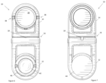
- FIGS. 6 and 7 correspond to FIG. 3 , and are elevational rear and front views of the bracket of FIG. 1 .
- FIG. 8 shows and exploded isometric view of another embodiment of a bracket.
- FIGS. 9 and 10 show rear and front exploded isometric views of the other arm of the bracket of FIG. 8 .
- FIGS. 11 and 12 show rear exploded isometric views of an arm of the bracket of FIG. 8 , less a suction cup assembly.
- FIG. 13 shows an exploded isometric view of the suction cup assembly of the bracket of FIG. 8 .
- FIG. 14 shows an isometric view of some of the suction cup assembly of FIG. 13 .
- FIG. 15 shows an isometric view of a helical ramp member of the suction cup assembly of FIG. 13 .
- FIG. 16 shows the bracket of FIG. 8 with a handle in an operational position.
- FIG. 1 shows a rear isometric view of an embodiment of a bracket for mounting a tablet shaped device, the bracket being generally indicated by the numeral 10 .
- a supporting structure in the form of the electronic display of a laptop computer 8 .
- An arm 12 of the bracket 10 is mounted to the rear face of the electronic display of the laptop computer 8 .
- the bracket 10 comprises another arm 14 .
- Mounted to one face 24 ( FIG. 4 ) of the other arm 14 is a tablet shaped device 6 in the form of an Apple iPhone 12 Pro, however generally any suitable tablet shaped device may be used, examples which include but are not limited to a tablet computer, a smart phone, and a personal digital assistant.
- Mounted to another face 26 ( FIG. 4 ) of the other arm 14 is a power transmitter 4 of a tablet shape device wireless charger in the form of an Apple MagSafe charger.
- the electronic display of the tablet shaped device 6 can be viewed while it is charging.
- FIGS. 2 and 3 show front isometric views of the bracket 10
- FIG. 4 shows a side elevation view of the bracket 10 , with the arms 12 , 14 meeting at vertex 16 to form an angle A (approximately 25 degrees) in FIG. 2 , a different angle B in FIG. 3 (approximately 180 degrees), and angle C (approximately 120 degrees) in FIG. 4
- the arm 12 and the other arm 14 are pivotally attached by a hinge 18 that pivotally couples the arm 12 and the other arm 14 .
- the angle at the vertex 16 can be changed by pivoting either arm 12 , 14 with respect to the other arm 14 , 12 .
- the hinge 18 is pivotable around a hinge axis 20 ( FIG.
- FIG. 5 is a detail from FIG. 1 , and shows another hinge axis 22 that is longitudinally orientated with respect to the arm 14 and perpendicular to the normal of faces 24 , 26 .
- the other arm 14 is pivotable around the other hinge axis 22 so it can be flipped around to present either face to the user.
- the phone can also be alternatively magnetically attached to the wireless transmitter 4 via internal magnets, which is useful if the spacing between the tablet shaped device and wireless transmitter needs to be reduced to enable charging, for example if the tablet shaped device is already in a protective case.
- the other arm 14 is pivotable 180° around the other hinge axis 22 .
- the hinge 18 is a plural axes hinge in the form of a dual axes hinge that provides pivoting around the two hinge axes 20 , 22 . Consequently, either one of the opposite faces 24 , 26 ( FIG. 4 ) of the other arm 14 can be presented to the user when the arm 12 is mounted to the supporting structure 8 .
- the hinge 18 is in the form of a torque hinge (also known as a friction hinge or free stop). The arm 12 and the other arm 14 can be relatively arranged and the torque hinge will hold the relative arrangement.
- the other arm 14 is configured to receive the power transmitter 4 —which has a disk configuration—of the wireless charger.
- An electrical cable 2 is in electrical communication with the power transmitter 4 of the wireless charger.
- the other arm has a socket 30 at a rounded end in which the power transmitter 4 of the wireless charger can be received, as shown in FIG. 1 .
- the wireless charger receiving socket 30 is complementarily configured to the wireless charger 28 , defining a circular opening for the power transmitter 4 , and which is substantially the same diameter as the body of the wireless transmitter 4 .
- a wall 34 At the periphery of the wireless charger receiving socket 30 is a wall 34 in the form of a peripheral outer wall.
- the wall 34 is interrupted and defines at least one wireless charger cable passageway 38 , in this embodiment three wireless charger cable passageways 38 angularly spaced 90 degrees apart, two of which are laterally located.
- Each passageway 38 allows the cable 6 to pass from an exterior into the socket 30 .
- the cable to can pass through whichever wireless charger cable passageway 36 that a user prefers or is best for a given orientation and arrangement of the bracket 10 .
- the arm 14 comprises ferromagnetic material that is magnetically attracted to the tablet shaped device.
- the iPhone 12 for example, comprises a magnetic assembly at a back face thereof and is magnetically attachable to the arm 14 .
- the ferromagnetic material comprises at least one magnet in the form of a rare earth or albino magnet, but may alternatively comprise a non-magnetic ferromagnetic material, for example steel.
- FIGS. 6 and 7 correspond to FIG. 3 , and are elevational rear and front views of the bracket 10 , with the arms 12 , 14 making an angle of 180 degrees at vertex 16 .
- the arm 12 comprises a suction cup assembly 42 for attachment to the supporting structure.
- the suction cup assembly 42 comprises a suction cup 44 visible in FIGS. 4 and 7 , for example.
- the suction cup assembly 42 comprises a suction cup actuator 46 in the form of a user operable suction cup rotary actuator for actuating the suction cup 44 . Operation of the suction cup assembly 42 will be described further below with reference to another embodiment of a bracket.
- FIG. 8 shows an exploded isometric view of another embodiment of a bracket, where parts similar or identical in form and/or function are similarly numbered.
- Other arm 14 comprises a rear other arm portion 48 and a front other arm portion 50 , which are cooperatively configured to attach—in this embodiment clip together—to form the other arm 14 .
- the rear other arm portion 48 has only two wireless charger cable passage ways 36 into wireless charger receiving socket 30 .
- the wireless charger cable passage ways 36 are angularly spaced 180° apart and laterally located on the opposite lateral sides of the other arm 14 .
- Another wall 52 at the bottom of the wireless charger socket 30 defines a finger receiving through hole 54 for removal of the wireless charger from the wireless charger receiving socket.
- the wireless charger 4 can be pressed with a finger inserted through the through hole 54 to press the wireless charger out of the wireless charger socket 30 .
- the interior surface 56 of wall 34 comprises a plurality of wireless charger gripping element 58 comprising a resilient material in the form of a thermoplastic elastomer (TPE), specifically in this but not all embodiments a thermoplastic polyurethane (TPU) 58 however generally TPS or generally any suitable form of TPE may be used.
- TPE thermoplastic elastomer
- TPU thermoplastic polyurethane
- the plurality of gripping elements 58 compress when the wireless charger 8 is received by the cavity 30 and due to their resiliency hold the wireless transmitter 4 within the cavity 30 .
- FIGS. 9 and 10 show rear and front exploded isometric views of the other arm 14 , which reveal an adhesive fastened magnetic array 67 in the form of a ring comprising a plurality of 2.6 mm thick rare earth magnets in the form of neodymium magnets, an adhesive fastened thermoplastic elastomer (TPE) ring 70 , and a gripping ring 68 having the gripping elements 58 integral therewith or alternatively/additionally attached thereto.
- Gripping ring 68 is received within a cavity 35 defined by wall 34 ( FIG. 10 ) with gripping elements 58 inserted within gripping element receiving apertures 69 ( FIG. 9 ) defined by the rear other arm portion 48 to protrude into wireless charger receiving socket 30 .
- FIGS. 11 and 12 show rear exploded isometric views of arm 12 , less the suction cup assembly 42 .
- Arm 12 comprises rear arm portion 60 and front arm portion 62 , which are cooperatively configured to mate and be fastened together.
- As seen in FIG. 8 housed within hinge cavity 60 defined by arm 12 is dual axes torque hinge 18 , which is attached to arms 12 , 14 by fasteners 63 in the form of screws.
- Torque hinge 18 has three arms 64 that form a “T” and that are received within longitudinal and lateral cavities 66 defined by the front portions 50 , 62 .
- the arm 12 comprises a suction cup assembly 42 for attachment to the supporting structure 8 .
- the suction cup assembly 42 is rotationally mounted.
- the suction cup assembly 42 comprises a suction cup 44 .
- FIG. 13 shows an exploded isometric view of the suction cup assembly 42
- FIG. 14 shows an isometric view of some of the suction cup assembly in an assembled state
- FIG. 15 shows an isometric view of a helical ramp member of the suction cup assembly.
- the suction cup assembly 42 comprises a suction cup actuator 46 in the form of a user operable suction cup rotary actuator 46 .
- the user operable suction cup rotary actuator 46 is operationally coupled to the suction cup 44 .
- boss 76 Attached to the centre of inwardly facing face 74 of the suction cup 44 is boss 76 , which is disposed within suction cup outwardly biasing element 78 in the form of an extension spring 78 .
- Boss 76 is inserted through boss aperture 80 defined by rotary bearing member 82 which bearingly receives helical ramp member 84 .
- Boss 76 also passes through another boss aperture 87 defined by helical ramp member 84 .
- a cam follower in the form of a pin 86 is transversely disposed through boss 76 .
- the helical ramp member 84 and the rotary bearing member 82 are intermediate the pin 86 and the suction cup 44 .
- Pin 86 is received by a pin receiver in the form of a pin cradle 92 defined by the rotary bearing member 82 .
- User control 88 in the form of a collapsible handle is attached to the helical ramp member 84 by pins 90 for rotary actuation of the helical ramp member.
- User control 88 is pivotable around pins 90 between collapsed ( FIG. 2 ) and operational positions ( FIG. 16 ).
- Clockwise rotary actuation of the helical member 84 moves a helical ramp or cam in contact with the pin 86 such that the pin is inwardly translated.
- Counterclockwise actuation of the helical member 84 allows biasing member 78 to outwardly translate the suction cup.
- Helical ramp member 84 comprises a cam follower bearing surface 122 that is followed by the cam follower 86 .
- the cam follower bearing surface 122 defines a plurality of cam follower capture cavities 120 in the form of a plurality of grooves in which the cam follower 86 can be captured to lock the suction cup in the attachment or non-attachment configurations.
- Helical ramp member 84 has tabs 110 configured to be clippingly received within apertures 112 for attachment of the helical ramp member 84 to the rotary bearing member 82 .
- Forks 116 at the apertures 112 guide the tabs into engagement.
- Closure 114 similarly clips to helical ramp member 84 .
- a user can retract the centre of the suction cup 44 to reduce the air pressure between the suction cup 44 and the supporting structure 8 to which the suction cup 44 is in contact with. Atmospheric pressure holds the suction cup 44 and consequently the bracket 10 to the supporting structure 8 .
- the user can also operate the suction cup rotary actuator 46 to extend the suction cup 44 centre and so release the suction cup 44 from the supporting structure 8 .
- Pull tab 112 allows the user to peel away the suction cup 44 from supporting structure 8 .
- the arm 12 comprises at least one—in this embodiment two—releasable rotation stops 96 engageable with the suction cup assembly to rotationally fix the suction cup assembly 42 with respect to portions 60 , 62 (“body).
- the suction cup assembly 42 defines a plurality of cavities 98 for receiving the releasable rotationally mounted rotation stops 96 .
- the relative position of the rotation stops 96 and the cavities may be reversed in embodiments. Generally, any form of rotation locking may be used.
- the releasable rotation stops 96 each comprise a pivotally mounted lever 100 mounted on pivot 72 and comprising a rotation stop end 104 , which each comprise a tab, configured to engage the suction cup assembly 42 .
- the rotation stop ends are biased towards the suction cup assembly by biasing member 102 in the form of springs outwardly biasing the other end of the lever 100 .
- the pivotally mounted lever 100 comprises an actuatable end 106 operationally coupled to a user control 108 in the form of a button also outwardly biased.
- the actuatable ends 106 are disposed in slots defined by user controls 108 .
- User control 108 is depressible to pivot the levers 100 to pivotally disengage the rotation stops 96 from suction cup assembly 42 , enabling the arm 14 to spin around the suction cup around suction cup rotation axis 118 ( FIG. 8 ), which is perpendicular the attachment face of the suction cup.
- the user controls 108 can be released to engage the rotation stops 96 with the suction cup assembly 42 .
- the arm may be rotated between vertical and horizontal orientations to change the tablet shaped device between portrait and landscape orientations.
Landscapes
- Engineering & Computer Science (AREA)
- General Engineering & Computer Science (AREA)
- Mechanical Engineering (AREA)
- Theoretical Computer Science (AREA)
- Computer Hardware Design (AREA)
- Human Computer Interaction (AREA)
- Physics & Mathematics (AREA)
- General Physics & Mathematics (AREA)
- Computer Networks & Wireless Communication (AREA)
- Power Engineering (AREA)
- Hooks, Suction Cups, And Attachment By Adhesive Means (AREA)
Abstract
Description
-
- A tablet shaped device may be used while not held the user's hand.
- A tablet shaped device may be conveniently mounted and orientated (by using 3 degrees of rotational freedom) during a teleconference.
- The angle of the tablet shape device may be selected to improve user experience and camera angle, for example.
- A tablet shaped device may be more conveniently used by a worker in front of a computer.
- A user may experience less fatigue and better ergonomics when.
-
- The supporting structure may be a freestanding computer monitor, a wall, a door, a household appliance in the form of a refrigerator, or generally any suitable form of structure.
- The hinge may have only the lateral hinge axis, or only the longitudinal hinge axis.
- The hinge may not be a torque hinge, and may alternatively or additionally have releasable screw locks, for example.
- Embodiments may not be configured to mount a wireless charger.
- Embodiment may have 0, 1, 2, 3, or more wireless charger cable passageways.
- Generally, any suitable form of wireless charger may be used as desired, examples of which include but are not limited to a Yootech Magsafe charger, a Zdago Magsafe charger, and wireless chargers that may not be magnetically attachable and may be attached using, for example, adhesive or mechanical fasteners.
- The suction cup may be actuated by a push actuator as an alternative to the rotary actuator, or the suction cup may be actuator-less.
- The suction cup assembly may not be rotationally mounted.
- Embodiments may accommodate differently shaped wireless charges, for example square charges.
- The suction cup may have a shape other than circular, for example square or oval.
Claims (16)
Applications Claiming Priority (2)
| Application Number | Priority Date | Filing Date | Title |
|---|---|---|---|
| AU2021102895 | 2021-05-27 | ||
| AU2021102895A AU2021102895A4 (en) | 2021-05-27 | 2021-05-27 | A bracket for mounting a tablet shaped device |
Publications (2)
| Publication Number | Publication Date |
|---|---|
| US20220378205A1 US20220378205A1 (en) | 2022-12-01 |
| US11712115B2 true US11712115B2 (en) | 2023-08-01 |
Family
ID=77195554
Family Applications (1)
| Application Number | Title | Priority Date | Filing Date |
|---|---|---|---|
| US17/332,739 Active US11712115B2 (en) | 2021-05-27 | 2021-05-27 | Bracket for mounting a tablet shaped device |
Country Status (2)
| Country | Link |
|---|---|
| US (1) | US11712115B2 (en) |
| AU (1) | AU2021102895A4 (en) |
Cited By (5)
| Publication number | Priority date | Publication date | Assignee | Title |
|---|---|---|---|---|
| US20210348710A1 (en) * | 2020-05-06 | 2021-11-11 | Tommie T. Daniels | Cellular phone carrier |
| US20230173992A1 (en) * | 2021-12-08 | 2023-06-08 | 1Lss, Inc | Fixed Angle Car Mount for a Mobile Device |
| US20230418330A1 (en) * | 2022-06-25 | 2023-12-28 | Lenovo (Singapore) Pte. Ltd | Computing System |
| US20250050818A1 (en) * | 2023-08-08 | 2025-02-13 | Annex Products Pty. Ltd. | Suction mount for a handheld electronic device accessory |
| US20250224050A1 (en) * | 2024-01-04 | 2025-07-10 | Matthew Robinson | Retainer for holding cords, cables and other items |
Families Citing this family (6)
| Publication number | Priority date | Publication date | Assignee | Title |
|---|---|---|---|---|
| USD1012088S1 (en) * | 2021-04-20 | 2024-01-23 | Stm Management Pty Ltd | Bracket for mounting a tablet shaped device |
| USD1009848S1 (en) * | 2021-06-02 | 2024-01-02 | Stm Management Pty Ltd | Bracket for mounting a tablet shaped device |
| HU5434U (en) * | 2021-06-08 | 2022-05-28 | Nemes Geza Sandor | Holder for holding and connecting industrial mobile devices |
| IT202200003987U1 (en) * | 2022-10-04 | 2024-04-04 | Ferraris Group S A G L | Support device for a portable processing and/or telecommunication apparatus or an accessory |
| IT202200020328A1 (en) * | 2022-10-04 | 2024-04-04 | Ferraris Group S A G L | Support device for a portable processing and/or telecommunication apparatus or an accessory |
| CN222706533U (en) * | 2024-06-24 | 2025-04-01 | 杰克布库·克里斯托夫 | Sucking disc support |
Citations (9)
| Publication number | Priority date | Publication date | Assignee | Title |
|---|---|---|---|---|
| US20150369418A1 (en) * | 2014-06-18 | 2015-12-24 | Helping Hands International Holdings Limited | Convertible stand/table |
| US20160173667A1 (en) * | 2014-12-11 | 2016-06-16 | Bernardino Ruben Torres Gutierrez | Magnetic mobile phone mounting kit |
| US20170328517A1 (en) * | 2016-05-12 | 2017-11-16 | Peter H. Wessels | Folding handheld device holding system |
| US9961306B1 (en) * | 2017-05-22 | 2018-05-01 | Yaron LEV | Smart holder |
| US20190195417A1 (en) * | 2017-12-21 | 2019-06-27 | Jonathan Caleb Kwasniewski | Mobile Device Mount |
| US20200063911A1 (en) * | 2018-08-21 | 2020-02-27 | Loctek Inc. | Desktop display stand base and its application to a desktop display stand assembly thereof |
| JP6664735B1 (en) * | 2018-10-09 | 2020-03-13 | 陽斗子 是枝 | Mobile communication terminal equipment case |
| US10703297B1 (en) * | 2016-08-26 | 2020-07-07 | Apple Inc. | System for holding devices in a passenger vehicle |
| US20220329113A1 (en) * | 2018-11-09 | 2022-10-13 | Wbtec, Llc | Mobile furniture panel |
-
2021
- 2021-05-27 US US17/332,739 patent/US11712115B2/en active Active
- 2021-05-27 AU AU2021102895A patent/AU2021102895A4/en not_active Ceased
Patent Citations (9)
| Publication number | Priority date | Publication date | Assignee | Title |
|---|---|---|---|---|
| US20150369418A1 (en) * | 2014-06-18 | 2015-12-24 | Helping Hands International Holdings Limited | Convertible stand/table |
| US20160173667A1 (en) * | 2014-12-11 | 2016-06-16 | Bernardino Ruben Torres Gutierrez | Magnetic mobile phone mounting kit |
| US20170328517A1 (en) * | 2016-05-12 | 2017-11-16 | Peter H. Wessels | Folding handheld device holding system |
| US10703297B1 (en) * | 2016-08-26 | 2020-07-07 | Apple Inc. | System for holding devices in a passenger vehicle |
| US9961306B1 (en) * | 2017-05-22 | 2018-05-01 | Yaron LEV | Smart holder |
| US20190195417A1 (en) * | 2017-12-21 | 2019-06-27 | Jonathan Caleb Kwasniewski | Mobile Device Mount |
| US20200063911A1 (en) * | 2018-08-21 | 2020-02-27 | Loctek Inc. | Desktop display stand base and its application to a desktop display stand assembly thereof |
| JP6664735B1 (en) * | 2018-10-09 | 2020-03-13 | 陽斗子 是枝 | Mobile communication terminal equipment case |
| US20220329113A1 (en) * | 2018-11-09 | 2022-10-13 | Wbtec, Llc | Mobile furniture panel |
Cited By (10)
| Publication number | Priority date | Publication date | Assignee | Title |
|---|---|---|---|---|
| US20210348710A1 (en) * | 2020-05-06 | 2021-11-11 | Tommie T. Daniels | Cellular phone carrier |
| US11994251B2 (en) * | 2020-05-06 | 2024-05-28 | Tommie T. Daniels | Cellular phone carrier |
| US20230173992A1 (en) * | 2021-12-08 | 2023-06-08 | 1Lss, Inc | Fixed Angle Car Mount for a Mobile Device |
| US11945371B2 (en) * | 2021-12-08 | 2024-04-02 | 1LSS Inc. | Fixed angle car mount for a mobile device |
| US12157421B2 (en) | 2021-12-08 | 2024-12-03 | 1Lss, Inc | Fixed angle car mount for a mobile device |
| US20230418330A1 (en) * | 2022-06-25 | 2023-12-28 | Lenovo (Singapore) Pte. Ltd | Computing System |
| US12032405B2 (en) * | 2022-06-25 | 2024-07-09 | Lenovo (Singapore) Pte. Ltd | Computing system |
| US20250050818A1 (en) * | 2023-08-08 | 2025-02-13 | Annex Products Pty. Ltd. | Suction mount for a handheld electronic device accessory |
| US12503062B2 (en) * | 2023-08-08 | 2025-12-23 | Annex Products Pty. Ltd. | Suction mount for a handheld electronic device accessory |
| US20250224050A1 (en) * | 2024-01-04 | 2025-07-10 | Matthew Robinson | Retainer for holding cords, cables and other items |
Also Published As
| Publication number | Publication date |
|---|---|
| AU2021102895A4 (en) | 2021-08-12 |
| US20220378205A1 (en) | 2022-12-01 |
Similar Documents
| Publication | Publication Date | Title |
|---|---|---|
| AU2021102895A4 (en) | A bracket for mounting a tablet shaped device | |
| US11330093B2 (en) | Magnetically connectable grip and connector for electronics | |
| US8385974B1 (en) | Grip attachment for a mobile phone | |
| US20120326003A1 (en) | Multi-function tablet computer grip with 360-degree rotating finger ringlet | |
| US9210977B2 (en) | Device for retaining a portable electric component | |
| US20210373609A1 (en) | Electronic device including hinge structure | |
| US20120118770A1 (en) | Tablet accessory | |
| US20230389684A1 (en) | Attachment for a mobile phone case | |
| WO2024051867A1 (en) | Electronic device accessory | |
| US20110299231A1 (en) | Rotatable Cases For Electronic Devices | |
| US20020173281A1 (en) | Folding portable telephone capable of selectively using free stop function and one touch open function | |
| US8264836B2 (en) | Battery cover latching mechanism and electronic device using the same | |
| US11083263B2 (en) | Cellular device case having a built-in mount | |
| CN209086689U (en) | Intelligent watch with adjustable shooting angle | |
| US11877108B1 (en) | Case for wireless earphones | |
| US20070117598A1 (en) | Battery cover latching assembly for portable electronic device | |
| CN110324472A (en) | Fixing device for mobile phone | |
| CN115016650A (en) | Electronic equipment protective sleeve and electronic equipment assembly | |
| US7375690B2 (en) | Antenna ring for electronic device | |
| WO2012031575A2 (en) | Mobile phone with enhanced functions | |
| CN207328311U (en) | For vehicle terminal and there is its vehicle | |
| CN219611988U (en) | Ear-hanging earphone and earphone kit | |
| CN114302277B (en) | Headphone compartment and headphone components | |
| US20050195970A1 (en) | Invisible double function hinge construction | |
| CN223786103U (en) | An electronic product stand |
Legal Events
| Date | Code | Title | Description |
|---|---|---|---|
| FEPP | Fee payment procedure |
Free format text: ENTITY STATUS SET TO UNDISCOUNTED (ORIGINAL EVENT CODE: BIG.); ENTITY STATUS OF PATENT OWNER: SMALL ENTITY |
|
| FEPP | Fee payment procedure |
Free format text: ENTITY STATUS SET TO SMALL (ORIGINAL EVENT CODE: SMAL); ENTITY STATUS OF PATENT OWNER: SMALL ENTITY |
|
| AS | Assignment |
Owner name: STM MANAGEMENT PTY LTD, AUSTRALIA Free format text: ASSIGNMENT OF ASSIGNORS INTEREST;ASSIGNORS:CHENEY, CRAIG;GOODRIDGE, JACOB;NYHOLM, ETHAN;SIGNING DATES FROM 20210809 TO 20210813;REEL/FRAME:057561/0264 |
|
| STPP | Information on status: patent application and granting procedure in general |
Free format text: RESPONSE TO NON-FINAL OFFICE ACTION ENTERED AND FORWARDED TO EXAMINER |
|
| STPP | Information on status: patent application and granting procedure in general |
Free format text: FINAL REJECTION MAILED |
|
| STPP | Information on status: patent application and granting procedure in general |
Free format text: PUBLICATIONS -- ISSUE FEE PAYMENT VERIFIED |
|
| STCF | Information on status: patent grant |
Free format text: PATENTED CASE |