US11709237B2 - LiDAR systems and methods - Google Patents
LiDAR systems and methods Download PDFInfo
- Publication number
- US11709237B2 US11709237B2 US16/916,630 US202016916630A US11709237B2 US 11709237 B2 US11709237 B2 US 11709237B2 US 202016916630 A US202016916630 A US 202016916630A US 11709237 B2 US11709237 B2 US 11709237B2
- Authority
- US
- United States
- Prior art keywords
- optical
- delay
- laser signal
- local oscillator
- delay line
- Prior art date
- Legal status (The legal status is an assumption and is not a legal conclusion. Google has not performed a legal analysis and makes no representation as to the accuracy of the status listed.)
- Active, expires
Links
Images


Classifications
-
- G—PHYSICS
- G01—MEASURING; TESTING
- G01S—RADIO DIRECTION-FINDING; RADIO NAVIGATION; DETERMINING DISTANCE OR VELOCITY BY USE OF RADIO WAVES; LOCATING OR PRESENCE-DETECTING BY USE OF THE REFLECTION OR RERADIATION OF RADIO WAVES; ANALOGOUS ARRANGEMENTS USING OTHER WAVES
- G01S17/00—Systems using the reflection or reradiation of electromagnetic waves other than radio waves, e.g. lidar systems
- G01S17/02—Systems using the reflection of electromagnetic waves other than radio waves
- G01S17/06—Systems determining position data of a target
- G01S17/08—Systems determining position data of a target for measuring distance only
- G01S17/32—Systems determining position data of a target for measuring distance only using transmission of continuous waves, whether amplitude-, frequency-, or phase-modulated, or unmodulated
-
- G—PHYSICS
- G01—MEASURING; TESTING
- G01S—RADIO DIRECTION-FINDING; RADIO NAVIGATION; DETERMINING DISTANCE OR VELOCITY BY USE OF RADIO WAVES; LOCATING OR PRESENCE-DETECTING BY USE OF THE REFLECTION OR RERADIATION OF RADIO WAVES; ANALOGOUS ARRANGEMENTS USING OTHER WAVES
- G01S7/00—Details of systems according to groups G01S13/00, G01S15/00, G01S17/00
- G01S7/48—Details of systems according to groups G01S13/00, G01S15/00, G01S17/00 of systems according to group G01S17/00
- G01S7/483—Details of pulse systems
- G01S7/486—Receivers
- G01S7/4865—Time delay measurement, e.g. time-of-flight measurement, time of arrival measurement or determining the exact position of a peak
-
- G—PHYSICS
- G01—MEASURING; TESTING
- G01S—RADIO DIRECTION-FINDING; RADIO NAVIGATION; DETERMINING DISTANCE OR VELOCITY BY USE OF RADIO WAVES; LOCATING OR PRESENCE-DETECTING BY USE OF THE REFLECTION OR RERADIATION OF RADIO WAVES; ANALOGOUS ARRANGEMENTS USING OTHER WAVES
- G01S17/00—Systems using the reflection or reradiation of electromagnetic waves other than radio waves, e.g. lidar systems
- G01S17/02—Systems using the reflection of electromagnetic waves other than radio waves
- G01S17/06—Systems determining position data of a target
- G01S17/08—Systems determining position data of a target for measuring distance only
- G01S17/10—Systems determining position data of a target for measuring distance only using transmission of interrupted, pulse-modulated waves
-
- G—PHYSICS
- G01—MEASURING; TESTING
- G01S—RADIO DIRECTION-FINDING; RADIO NAVIGATION; DETERMINING DISTANCE OR VELOCITY BY USE OF RADIO WAVES; LOCATING OR PRESENCE-DETECTING BY USE OF THE REFLECTION OR RERADIATION OF RADIO WAVES; ANALOGOUS ARRANGEMENTS USING OTHER WAVES
- G01S17/00—Systems using the reflection or reradiation of electromagnetic waves other than radio waves, e.g. lidar systems
- G01S17/02—Systems using the reflection of electromagnetic waves other than radio waves
- G01S17/06—Systems determining position data of a target
- G01S17/42—Simultaneous measurement of distance and other co-ordinates
-
- G—PHYSICS
- G01—MEASURING; TESTING
- G01S—RADIO DIRECTION-FINDING; RADIO NAVIGATION; DETERMINING DISTANCE OR VELOCITY BY USE OF RADIO WAVES; LOCATING OR PRESENCE-DETECTING BY USE OF THE REFLECTION OR RERADIATION OF RADIO WAVES; ANALOGOUS ARRANGEMENTS USING OTHER WAVES
- G01S17/00—Systems using the reflection or reradiation of electromagnetic waves other than radio waves, e.g. lidar systems
- G01S17/88—Lidar systems specially adapted for specific applications
- G01S17/89—Lidar systems specially adapted for specific applications for mapping or imaging
-
- G—PHYSICS
- G01—MEASURING; TESTING
- G01S—RADIO DIRECTION-FINDING; RADIO NAVIGATION; DETERMINING DISTANCE OR VELOCITY BY USE OF RADIO WAVES; LOCATING OR PRESENCE-DETECTING BY USE OF THE REFLECTION OR RERADIATION OF RADIO WAVES; ANALOGOUS ARRANGEMENTS USING OTHER WAVES
- G01S7/00—Details of systems according to groups G01S13/00, G01S15/00, G01S17/00
- G01S7/48—Details of systems according to groups G01S13/00, G01S15/00, G01S17/00 of systems according to group G01S17/00
- G01S7/481—Constructional features, e.g. arrangements of optical elements
- G01S7/4817—Constructional features, e.g. arrangements of optical elements relating to scanning
-
- G—PHYSICS
- G01—MEASURING; TESTING
- G01S—RADIO DIRECTION-FINDING; RADIO NAVIGATION; DETERMINING DISTANCE OR VELOCITY BY USE OF RADIO WAVES; LOCATING OR PRESENCE-DETECTING BY USE OF THE REFLECTION OR RERADIATION OF RADIO WAVES; ANALOGOUS ARRANGEMENTS USING OTHER WAVES
- G01S7/00—Details of systems according to groups G01S13/00, G01S15/00, G01S17/00
- G01S7/48—Details of systems according to groups G01S13/00, G01S15/00, G01S17/00 of systems according to group G01S17/00
- G01S7/497—Means for monitoring or calibrating
Definitions
- LiDAR Light detection and ranging
- energy such as laser light can be directed toward a target object, and the energy reflected by the target object can be detected and measured by a sensor or detector.
- the distance to the target object can be calculated based on the speed of the light and the time it takes for energy to travel to the target object and back to the sensor.
- LiDAR can use ultraviolet, visible, or near-infrared sources to sense, image, identify, or map objects.
- the sensor uses coherent detection, where a portion of the energy from the laser is separated and made to interfere optically with the energy reflected by the target.
- LiDAR loses signal if the target is farther than half of the coherence length of the light source.
- coherence can be restored if an equivalent delay is introduced to the separated light prior to interference.
- the delay could be introduced via coiled optical fibers.
- a technology disclosed herein includes generating a laser signal with a light source of a light detection and ranging system, splitting the laser signal with an optical signal splitter circuit of the light detection and ranging system to produce a first laser signal for transmission to a target and a second laser signal, known as the local oscillator (LO), transmitting the first laser signal to the target with an optical signal scanner of the light detection and ranging system, wherein the first laser signal is reflected by the target to produce a scattered receiver beam, routing the second laser signal through an optical delay line of the light detection and ranging system, wherein the optical delay line adds a predetermined time delay to the second laser signal to generate a delayed second laser signal, and receiving the scattered receiver beam and the delayed second laser signal with a detector of the light detection and ranging system.
- LO local oscillator
- FIG. 1 illustrates an example block diagram of a LiDAR system having an optical delay line.
- FIG. 2 illustrates a block diagram of a LiDAR system having an optical switching circuit with multiple optical delay lines in parallel.
- FIG. 3 illustrates a block diagram of a LiDAR system having an optical switching circuit with multiple optical delay lines in series.
- FIG. 4 illustrates example operations for utilizing an example LiDAR system having an optical delay line.
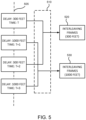
- FIG. 5 illustrates a schematic of a method for performing interleaving in an LiDAR system.
- FIG. 6 illustrates a comparison graph of signal-to-noise ratio (SNR) curves for two LiDAR systems.
- FIG. 7 illustrates an example processing system that may be useful in implementing the described technology.
- Implementations described herein provide systems for using one or more optical delay lines in a coherent light detection and ranging (LiDAR) system.
- a plurality of optical delay lines can be provided between an optical signal source and an optical signal detector of a light detection and ranging (LiDAR) system.
- An optical switch may be used to select one of the plurality of optical delay lines to add a spatial optical delay before the signal is input to the optical signal detector.
- the optical signal may be divided into a plurality of (temporally) interleaving frames, wherein each of the interleaving frames corresponds to a combination of different target (ranging) distance and optical delay line.
- one or more optical delay lines can be used to improve long range LiDAR coherence.
- Embodiments of the present invention encompass systems and methods which employ the use of an optical delay in part of a coherent LiDAR system. Such embodiments can operate to extend the maximum range of a given coherent LiDAR system. Such embodiments can also reduce the constraints on how thin the laser linewidth must be in order to meet a given range target. In some cases, embodiments can enable switching between two or more sets of optical delays to allow a given system to scan targets in different range sets. For example, a system could switch between different delays for a “short”, “medium”, and “long” range setting.
- FIG. 1 schematically illustrates aspects of an exemplary coherent LiDAR system 100 , according to embodiments of the present invention.
- system 100 includes a light source 110 , a splitter 115 , a modulator 120 , a scanner 130 , an optical mixer 135 , and a detector 140 .
- source 110 can be configured to provide any desired type of electromagnetic waves.
- the splitter 115 may be configured to split the electromagnetic waves from the source 110 into two output electromagnetic waves, one of which is used as a local oscillator (LO) 150 .
- scanner 130 is an optical signal scanner.
- scanner 130 includes a collection lens.
- light 112 from the light source 110 is modulated in some way, for example continuous frequency shift or pseudo-random binary sequence (PRBS) pattern on the phase, by the modulator 120 and sent through the scanner 130 to a target 190 .
- a transmitter beam Tx (incident light or target beam) is emitted from the scanner 130 , and reflected by the target 190 to provide a receiver beam Rx (scattered light).
- the transmitter beam Tx is scanned by the scanner throughout an angular field, for example the angular field can correspond to a 30° field of view, a 60° field of view, or any other desired angular field of view.
- the scanner 130 is also configured to collect the scattered light Rx.
- coherent LiDAR involves optically mixing scattered light Rx collected from a target and a local oscillator reference beam 150 .
- the optical mixer 135 does the mixing or addition of the Rx and the LO 152 .
- the output from the optical mixer is input to the detector 140 .
- the light in the LO 152 is substantially correlated with the light in the Rx, resulting in higher signal to noise ratio (SNR) for the detector 140 .
- SNR signal to noise ratio
- laser light has a finite spread of frequencies, called the linewidth, which adds some randomness to the electric fields.
- a LiDAR system that is rated to provide a 1.5 MHz laser linewidth may in fact provide frequency values within a range from 200 THz to 200.0000015 THz.
- the nonzero linewidth reduces the correlation between the optical electric fields of the two arms, an effect known as decoherence.
- the wavelength may vary as well.
- SNR signal-to-noise ratio
- the system 100 includes a local oscillator 150 having a delay arm 160 .
- the delay arm 160 provides a delay distance d to the local oscillator 150 .
- a spatial optical delay d can operate to balance the arms ( 150 , Rx) of the detector 140 for a target at a range d/2, or a total round-trip delay d. The decoherence losses at this distance will then be substantially reduced to zero.
- the delay line 160 is an optical delay line that may be implemented using cavity delay, optical fiber delay, free space delay, etc.
- the delay line 160 applies a transform to the local oscillator signal 150 to generate a delayed laser signal 152 by delaying it by a predetermined time.
- the optical delay 160 can take the form of a long fiber (e.g. where longer fiber lengths provide longer delays).
- the long fiber can be provided as a loop of fiber.
- the optical delay 160 can take the form of an optical cavity.
- the nature of the modulation provides information on the travel time and therefore allows the detector 140 to extract the range to the target 190 . If the local oscillator light 150 and the scattered light Rx light maintain coherence, the signal from the scattered light Rx experiences a large gain, which in the absence of the delay line 160 decreases exponentially with target range, as decoherence effects begin to appear.
- the distance to the target object can be calculated based on the speed of the energy and the time it takes for energy to travel to the target object and back to the detector. In some embodiments, by comparing and/or correlating the LO reference beam and Rx beam at any given point in time, it is possible to calculate distance to a single point on the target. Therefore, scanning the transmitted laser signal Tx over the target allows determining the shape and topology details of the target (e.g. by analyzing various points or locations on the target).
- a delay distance d by optical delay 160 to the local oscillator 150 causes the local oscillator (LO) arm 150 and the scattered light arm Rx to be balanced, and therefore correlated, at a target distance d/2 (round trip distance d).
- This allows for the engineering or selection of what target distances will experience decoherence losses.
- One approach is to set the local oscillator delay 160 to match twice the maximum desired target distance between the scanner 130 and target 190 , which will then have close targets experience the worst decoherence losses.
- nearby targets also have the highest amount of light available to harvest, which in many cases will result in a wider set of target ranges that yield a signal above the noise floor.
- a LiDAR system can be configured for use with a target distance of 150 feet and a round trip distance of 300 feet, where the delay distance is 300 feet. The inclusion of the delay will operate to cancel out the loss due to non-zero linewidth.
- the target distance may not always have a fixed value.
- a LiDAR system can incorporate a variable or adjustable delay to facilitate operation in such instances.
- a LiDAR system can be configured to provide a first delay of 300 feet for targets at 150 feet, and a second delay of 1000 feet for targets at 500 feet. In this way, LiDAR systems can be designed to analyze different target distances.
- FIG. 2 schematically illustrates aspects of an exemplary coherent LiDAR system 200 , according to embodiments of the present invention.
- the system 200 shown in FIG. 2 can include one or more features of, or can perform one or more of the functional aspects of, the system 100 shown in FIG. 1 .
- system 200 includes a light source 210 , a splitter 215 , a modulator 220 , a scanner 230 , an optical mixer 235 , and a detector 240 .
- light 212 from the light source 210 is modulated by the modulator 220 and sent through the scanner 230 to a target 290 .
- a transmitter beam Tx (incident light) is emitted from the scanner 230 , and scattered or reflected by the target 290 to provide a receiver beam Rx (scattered light).
- the scattered light Rx is collected and combined with the local oscillator reference beam 250 by the optical mixer 235 and detected by the detector 240 .
- the Rx light has the modulation pattern from the modulator and is delayed due to the travel time to the target 290 . This information can be extracted by the detector 240 when combined with the reference beam and is used to calculate the distance to the target 290 .
- System 200 includes an optical switching circuit 255 having an optical switch 270 that can operate to incorporate either a first local oscillator delay 262 or a second local oscillator delay 264 into the local oscillator reference beam 250 .
- the first local oscillator delay 262 and the second local oscillator delay 264 are arranged in parallel.
- the optical switch 270 can operate to change between different local oscillator delays ( 262 , 264 ) to switch the LiDAR system 200 between different sets of detection ranges. This can allow the system 200 to balance the detection arms at two or more ranges.
- an optical switch can be integrated to switch the local oscillator between two or more sets of delays to give the LiDAR system two or more sets of ranges it can address.
- the first delay 262 may provide a 300-foot delay while the second delay 264 may provide a 1000-foot delay.
- FIG. 3 schematically illustrates aspects of an exemplary coherent LiDAR system 300 , according to embodiments of the present invention.
- the system 300 shown in FIG. 3 can include one or more features of, or can perform one or more of the functional aspects of, the system 100 shown in FIG. 1 or the system 200 shown in FIG. 2 .
- system 300 includes a light source 310 , a splitter 315 , a modulator 320 , a scanner 330 , an optical mixer 335 , and a detector 340 .
- light 312 from the light source 310 is modulated by the modulator 320 and sent through the scanner 330 to a target 390 .
- a transmitter beam Tx (incident light) is emitted from the scanner 330 , and reflected by the target 390 to provide a receiver beam Rx (scattered light).
- the scattered light Rx is collected and combined with the local oscillator reference beam 350 by the optical mixer 335 and detected by the detector 340 .
- the distance to the target object can be calculated based on the speed of the energy and the time it takes for energy to travel to the target object and back to the detector.
- System 300 includes an optical switching circuit 355 having two optical switches S1 and S2 that can operate to incorporate either no delay 366 (D0), a first local oscillator delay 362 (D1), or a first local oscillator delay 362 (D1) in series with a second local oscillator delay 364 (D2) into the local oscillator reference beam 350 .
- the first local oscillator delay 362 and the second local oscillator delay 364 are arranged in series.
- the optical switches S1 and S2 can operate to change between different local oscillator delays ( 362 , 364 , 366 ) to switch the LiDAR system 300 between different sets of detection ranges. This can allow the system 300 to balance the detection arms at three or more ranges.
- an optical switch can be integrated to switch the local oscillator between two or more sets of delays to give the LiDAR system two or more sets of ranges it can address.
- first delay 362 can provide a 30 foot delay and second delay 364 can provide a 70 foot delay.
- an optical switching circuit that is arranged in series can provide a more spatially compact design as compared with an optical switching circuit that is arranged in parallel.
- Table 1 provided below illustrates how the settings of the optical switches can be configured (e.g. by setting optical switch S1 to provide connection S1-1 or connection S1-2), so as to achieve the desired optical delay effect for the optical switching circuit 355 .
- FIG. 4 illustrates example operations 400 for utilizing an example LiDAR system ledger described herein.
- One or more of the operations 400 may be implemented or controlled using a processor on a LiDAR system (such as the LiDAR system 100 illustrated in FIG. 1 ).
- An operation 410 generates a laser signal with a light source of the light detection and ranging system.
- operation 410 can involve generating any desired type of electromagnetic waves using an electromagnetic wave source.
- An operation 420 splits the laser signal with an optical signal splitter circuit of the light detection and ranging system, for example to produce a first laser signal for transmission to a target and a second laser signal.
- An operation 430 transmits the first laser signal to the target with an optical signal scanner of the light detection and ranging system.
- the first laser signal is reflected by the target to produce a scattered receiver beam.
- An operation 440 receives the second laser signal with an optical delay line of the light detection and ranging system.
- the optical delay line adds a predetermined time delay to the second laser signal to generate a delayed second laser signal.
- An operation 450 receives the scattered receiver beam and the delayed second laser signal with a detector of the light detection and ranging system.
- an optical switch can be integrated to switch the local oscillator between two or more sets of delays to give the LiDAR system two or more sets of ranges it can address. This can be accomplished by interleaving frames (e.g. one short range frame, followed by a long range frame) or by switching to different detection modes as specified by a decision algorithm.
- Such an optical delay line can enable the use of an affordable laser (which can be a difficult cost point in coherent LiDAR) to achieve the same performance, or alternatively improved performance from the same laser.
- a LiDAR system can incorporate a variable or adjustable delay to facilitate operation in such instances.
- a LiDAR system can be configured to provide switching between a first delay of 300 feet for targets at 150 feet, and a second delay of 1000 feet for targets at 500 feet.
- LiDAR systems can be designed to analyze different target distances.
- Such LiDAR systems can also incorporate a multiplex functionality in the time domain, whereby signals associated with the first delay alternate with signals associated with the second delay (e.g. one signal per microsecond) due to operation of the switching circuit.
- FIG. 5 depicts aspects of an interleaving circuit 510 (e.g. a laser signal interleaving circuit) that can be used in a LiDAR system to evaluate such signals.
- a series of signals 505 corresponding to two target ranging distances can be processed by the interleaving circuit 510 to produce a first set of interleaving frames 520 corresponding to the first target ranging distance and a second set of interleaving frames 530 corresponding to the second target ranging distance.
- the LiDAR system may switch between two or more optical delays, and acquire a complete image (frame) with each of the delays.
- Each frame will then be optimized for a particular set of ranges depending on the delay for that particular frame.
- the LiDAR system switched between 300 and 1000 ft delays. Such switching may be, for example, 12 times per second, so that the LiDAR can acquire a complete image (“frame”) with each delay.
- an optical delay line switch can be configured to select a different combination of two or more optical delay lines, where each of the different combinations correspond to one of the two or more temporally interleaving frames.
- FIG. 6 illustrates a comparison of relative signal-to-noise ratio (SNR) curves between two LiDAR systems with 1 MHz laser linewidth.
- Curve A corresponds to a LiDAR system having no decoherence, and shows the signal decrease purely as a function of collected power.
- Curve B corresponds to a LiDAR system having no delay line, and a 1 MHz linewidth. The signal drops off much more quickly with distance as decoherence effects become significant.
- Curve C corresponds to a LiDAR system having a 240 m delay on the local oscillator.
- the system with no delay arm, as represented by B is designed to have a maximum target range of 100 m before it hits the noise floor (horizontal line D).
- the noise floor D represents the limit of detectability.
- the system with a 240 m delay arm brings the signal up so that it does not hit the noise floor until the target is past a 150 m distance, improving the maximum range by more than 50 m.
- the system with the 240 m LO delay produces a lower signal at sub-60 m ranges than the standard system, but the large amount of light collected from nearby targets ensures the signal remains well above the noise floor and is readily detectable. Therefore, the addition of the delay arm has improved the system maximum range with no other trade-offs.
- FIG. 7 illustrates an example processing system 700 that may be useful in implementing the described technology.
- the processing system 700 is capable of executing a computer program product embodied in a tangible computer-readable storage medium to execute a computer process.
- Data and program files may be input to the processing system 700 , which reads the files and executes the programs therein using one or more processors (CPUs or GPUs).
- processors CPUs or GPUs.
- FIG. 7 wherein a processor 702 is shown having an input/output (I/O) section 704 , a Central Processing Unit (CPU) 706 , and a memory section 708 .
- I/O input/output
- CPU Central Processing Unit
- the processing system 700 may be a conventional computer, a distributed computer, or any other type of computer.
- the described technology is optionally implemented in software loaded in memory 708 , a storage unit 712 , and/or communicated via a wired or wireless network link 714 on a carrier signal (e.g., Ethernet, 3G wireless, 8G wireless, LTE (Long Term Evolution)) thereby transforming the processing system 700 in FIG. 7 to a special purpose machine for implementing the described operations.
- the processing system 700 may be an application specific processing system configured for supporting one or more aspects of a LiDAR system.
- the I/O section 704 may be connected to one or more user-interface devices (e.g., a keyboard, a touch-screen display unit 718 , etc.) or a storage unit 712 .
- user-interface devices e.g., a keyboard, a touch-screen display unit 718 , etc.
- Storage unit 712 e.g., a hard disk drive, a solid state drive, etc.
- Computer program products containing mechanisms to effectuate the systems and methods in accordance with the described technology may reside in the memory section 508 or on the storage unit 712 of such a system 700 .
- a communication interface 724 is capable of connecting the processing system 700 to an enterprise network via the network link 714 , through which the computer system can receive instructions and data embodied in a carrier wave.
- the processing system 700 When used in a local area networking (LAN) environment, the processing system 700 is connected (by wired connection or wirelessly) to a local network through the communication interface 724 , which is one type of communications device.
- the processing system 700 When used in a wide-area-networking (WAN) environment, the processing system 700 typically includes a modem, a network adapter, or any other type of communications device for establishing communications over the wide area network.
- program modules depicted relative to the processing system 700 or portions thereof may be stored in a remote memory storage device. It is appreciated that the network connections shown are examples of communications devices for and other means of establishing a communications link between the computers may be used.
- a user interface software module, a communication interface, an input/output interface module, a ledger node, and other modules may be embodied by instructions stored in memory 708 and/or the storage unit 712 and executed by the processor 702 .
- local computing systems, remote data sources and/or services, and other associated logic represent firmware, hardware, and/or software, which may be configured to assist in supporting a LiDAR system.
- One or more aspects of a LiDAR system may be implemented using a general-purpose computer and specialized software (such as a server executing service software), a special purpose computing system and specialized software (such as a mobile device or network appliance executing service software), or other computing configurations.
- keys, device information, identification, configurations, etc. may be stored in the memory 708 and/or the storage unit 712 and executed by the processor 702 .
- the processing system 700 may be implemented in a device, such as a user device, storage device, IoT device, a desktop, laptop, computing device.
- the processing system 700 may execute in a user device or external to a user device.
- Data storage and/or memory may be embodied by various types of processor-readable storage media, such as hard disc media, a storage array containing multiple storage devices, optical media, solid-state drive technology, ROM, RAM, and other technology.
- the operations may be implemented processor-executable instructions in firmware, software, hard-wired circuitry, gate array technology and other technologies, whether executed or assisted by a microprocessor, a microprocessor core, a microcontroller, special purpose circuitry, or other processing technologies.
- a write controller, a storage controller, data write circuitry, data read and recovery circuitry, a sorting module, and other functional modules of a data storage system may include or work in concert with a processor for processing processor-readable instructions for performing a system-implemented process.
- the term “memory” means a tangible data storage device, including non-volatile memories (such as flash memory and the like) and volatile memories (such as dynamic random-access memory and the like).
- the computer instructions either permanently or temporarily reside in the memory, along with other information such as data, virtual mappings, operating systems, applications, and the like that are accessed by a computer processor to perform the desired functionality.
- the term “memory” expressly does not include a transitory medium such as a carrier signal, but the computer instructions can be transferred to the memory wirelessly.
- intangible computer-readable communication signals may embody computer readable instructions, data structures, program modules or other data resident in a modulated data signal, such as a carrier wave or other signal transport mechanism.
- modulated data signal means a signal that has one or more of its characteristics set or changed in such a manner as to encode information in the signal.
- intangible communication signals include wired media such as a wired network or direct-wired connection, and wireless media such as acoustic, RF, infrared and other wireless media.
- the embodiments of the invention described herein are implemented as logical steps in one or more computer systems.
- the logical operations of the present invention are implemented (1) as a sequence of processor-implemented steps executing in one or more computer systems and (2) as interconnected machine or circuit modules within one or more computer systems.
- the implementation is a matter of choice, dependent on the performance requirements of the computer system implementing the invention. Accordingly, the logical operations making up the embodiments of the invention described herein are referred to variously as operations, steps, objects, or modules.
- logical operations may be performed in any order, unless explicitly claimed otherwise or a specific order is inherently necessitated by the claim language.
Landscapes
- Engineering & Computer Science (AREA)
- Physics & Mathematics (AREA)
- Computer Networks & Wireless Communication (AREA)
- General Physics & Mathematics (AREA)
- Radar, Positioning & Navigation (AREA)
- Remote Sensing (AREA)
- Electromagnetism (AREA)
- Optical Radar Systems And Details Thereof (AREA)
Abstract
Description
| TABLE 1 | |||
| S1 | S2 | ||
| D0 (No Delay) | S1-1 | — | ||
| D1 Delay | S1-2 | S2-1 | ||
| D1 + D2 Delay | S1-2 | S2-2 | ||
Claims (20)
Priority Applications (1)
| Application Number | Priority Date | Filing Date | Title |
|---|---|---|---|
| US16/916,630 US11709237B2 (en) | 2020-06-30 | 2020-06-30 | LiDAR systems and methods |
Applications Claiming Priority (1)
| Application Number | Priority Date | Filing Date | Title |
|---|---|---|---|
| US16/916,630 US11709237B2 (en) | 2020-06-30 | 2020-06-30 | LiDAR systems and methods |
Publications (2)
| Publication Number | Publication Date |
|---|---|
| US20210405164A1 US20210405164A1 (en) | 2021-12-30 |
| US11709237B2 true US11709237B2 (en) | 2023-07-25 |
Family
ID=79031759
Family Applications (1)
| Application Number | Title | Priority Date | Filing Date |
|---|---|---|---|
| US16/916,630 Active 2040-12-29 US11709237B2 (en) | 2020-06-30 | 2020-06-30 | LiDAR systems and methods |
Country Status (1)
| Country | Link |
|---|---|
| US (1) | US11709237B2 (en) |
Families Citing this family (4)
| Publication number | Priority date | Publication date | Assignee | Title |
|---|---|---|---|---|
| US12386045B1 (en) | 2021-02-16 | 2025-08-12 | Apple Inc. | Enhanced LiDAR measurements using chirp nonlinearities |
| US12498462B2 (en) | 2022-05-12 | 2025-12-16 | Apple Inc. | LiDAR array with vertically-coupled transceivers |
| US20240004045A1 (en) * | 2022-06-30 | 2024-01-04 | Apple Inc. | Mitigation of phase noise due to back-scatter in coherent optical sensing |
| CN120103366B (en) * | 2025-02-17 | 2025-11-25 | 福州大学 | A Monte Carlo-based range-gated imaging simulation method |
Citations (8)
| Publication number | Priority date | Publication date | Assignee | Title |
|---|---|---|---|---|
| US4533242A (en) * | 1982-09-28 | 1985-08-06 | The United States Of America As Represented By The Administrator Of The National Aeronautics And Space Administration | Ranging system which compares an object-reflected component of a light beam to a reference component of the light beam |
| US20060290917A1 (en) * | 2005-06-24 | 2006-12-28 | The Boeing Company | Chirped synthetic wave laser radar apparatus and methods |
| US20110032509A1 (en) * | 2009-08-07 | 2011-02-10 | Faro Technologies, Inc. | Absolute distance meter with optical switch |
| US20170146641A1 (en) | 2006-09-22 | 2017-05-25 | Leica Geosystems Ag | Lidar system |
| US20180217258A1 (en) | 2017-01-31 | 2018-08-02 | Panasonic Intellectual Property Management Co., Ltd. | Imaging system |
| US20190239753A1 (en) | 2018-02-06 | 2019-08-08 | Kendall Research Systems, LLC | Interleaved photon detection array for optically measuring a physical sample |
| US20200116832A1 (en) * | 2018-10-11 | 2020-04-16 | GM Global Technology Operations LLC | Multiple beam, single mems lidar |
| US20210341611A1 (en) * | 2020-05-04 | 2021-11-04 | Silc Technologies, Inc. | Lidar with delayed reference signal |
-
2020
- 2020-06-30 US US16/916,630 patent/US11709237B2/en active Active
Patent Citations (8)
| Publication number | Priority date | Publication date | Assignee | Title |
|---|---|---|---|---|
| US4533242A (en) * | 1982-09-28 | 1985-08-06 | The United States Of America As Represented By The Administrator Of The National Aeronautics And Space Administration | Ranging system which compares an object-reflected component of a light beam to a reference component of the light beam |
| US20060290917A1 (en) * | 2005-06-24 | 2006-12-28 | The Boeing Company | Chirped synthetic wave laser radar apparatus and methods |
| US20170146641A1 (en) | 2006-09-22 | 2017-05-25 | Leica Geosystems Ag | Lidar system |
| US20110032509A1 (en) * | 2009-08-07 | 2011-02-10 | Faro Technologies, Inc. | Absolute distance meter with optical switch |
| US20180217258A1 (en) | 2017-01-31 | 2018-08-02 | Panasonic Intellectual Property Management Co., Ltd. | Imaging system |
| US20190239753A1 (en) | 2018-02-06 | 2019-08-08 | Kendall Research Systems, LLC | Interleaved photon detection array for optically measuring a physical sample |
| US20200116832A1 (en) * | 2018-10-11 | 2020-04-16 | GM Global Technology Operations LLC | Multiple beam, single mems lidar |
| US20210341611A1 (en) * | 2020-05-04 | 2021-11-04 | Silc Technologies, Inc. | Lidar with delayed reference signal |
Non-Patent Citations (1)
| Title |
|---|
| Baghmisheh, Behnam Behroozpour, "Chip-scale Lidar", EECS Department, University of California, Berkeley, Technical Report No. UCB/EECS-2017-4; Jan. 19, 2017. |
Also Published As
| Publication number | Publication date |
|---|---|
| US20210405164A1 (en) | 2021-12-30 |
Similar Documents
| Publication | Publication Date | Title |
|---|---|---|
| US11709237B2 (en) | LiDAR systems and methods | |
| US10488495B2 (en) | Single laser LIDAR system | |
| US20260118481A1 (en) | Anti-interference processing method and apparatus for multi-pulse laser radar system | |
| EP3113390B1 (en) | Device and method for monitoring optical performance parameter, and optical transmission system | |
| KR20230074273A (en) | lidar system and operation method | |
| CN103576162A (en) | Laser radar device and method for measuring target object distance through device | |
| US20220276382A1 (en) | Homodyne receive architecture in a spatial estimation system | |
| WO2019224982A1 (en) | Optical distance measurement device and processing device | |
| JPWO2017187484A1 (en) | Object imaging device | |
| CN114814856B (en) | A laser radar system based on heterodyne detection | |
| WO2018233502A1 (en) | Data transmission method, device, and system | |
| CN105068083B (en) | A kind of method for realizing the imaging of single pixel laser radar longitudinal super resolution rate | |
| CN114651174A (en) | Optical fiber distribution measurement system and signal processing method for optical fiber distribution measurement | |
| CN112305550A (en) | Coherent detection device and method | |
| US9303974B2 (en) | Angular resolution of images using photons having non-classical states | |
| CN115808294A (en) | A method and device for measuring time delay of an optical device based on coherent reception | |
| CN108462576B (en) | Local active phase compensation method and system | |
| CN115934036B (en) | A quantum random number management system and method based on single light source | |
| US12416728B2 (en) | Quantum lidar system | |
| KR102668739B1 (en) | Method and apparatus for target detection | |
| JP6039744B1 (en) | Noise figure measurement method, noise figure measurement apparatus, and measurement system | |
| CN114204987A (en) | Method and device for detecting phase difference and time delay of coherent receiver and storage medium | |
| WO2021202395A1 (en) | Time of flight ranging system using multi-valued signals | |
| CN118999759B (en) | A distributed high-frequency vibration monitoring method and device with ultra-large measurement range | |
| JP2007036513A (en) | Photon receiver and method for receiving photon |
Legal Events
| Date | Code | Title | Description |
|---|---|---|---|
| FEPP | Fee payment procedure |
Free format text: ENTITY STATUS SET TO UNDISCOUNTED (ORIGINAL EVENT CODE: BIG.); ENTITY STATUS OF PATENT OWNER: LARGE ENTITY |
|
| STPP | Information on status: patent application and granting procedure in general |
Free format text: NON FINAL ACTION MAILED |
|
| STPP | Information on status: patent application and granting procedure in general |
Free format text: RESPONSE TO NON-FINAL OFFICE ACTION ENTERED AND FORWARDED TO EXAMINER |
|
| STPP | Information on status: patent application and granting procedure in general |
Free format text: FINAL REJECTION MAILED |
|
| AS | Assignment |
Owner name: LUMINAR TECHNOLOGIES, INC., FLORIDA Free format text: ASSIGNMENT OF ASSIGNORS INTEREST;ASSIGNORS:SEAGATE TECHNOLOGY LLC;SEAGATE SINGAPORE INTERNATIONAL HEADQUARTERS PTE. LTD;REEL/FRAME:063116/0289 Effective date: 20230118 |
|
| STPP | Information on status: patent application and granting procedure in general |
Free format text: PUBLICATIONS -- ISSUE FEE PAYMENT VERIFIED |
|
| STCF | Information on status: patent grant |
Free format text: PATENTED CASE |
|
| AS | Assignment |
Owner name: GLAS TRUST COMPANY LLC, NEW JERSEY Free format text: SECURITY INTEREST;ASSIGNORS:LIMINAR TECHNOLOGIES, INC;LUMINAR, LLC;FREEDOM PHOTONICS LLC;REEL/FRAME:069312/0713 Effective date: 20240808 Owner name: GLAS TRUST COMPANY LLC, NEW JERSEY Free format text: SECURITY INTEREST;ASSIGNORS:LUMINAR TECHNOLOGIES, INC;LUMINAR , LLC;FREEDOM PHOTONICS LLC;REEL/FRAME:069312/0669 Effective date: 20240808 |
|
| AS | Assignment |
Owner name: GLAS TRUST COMPANY LLC, NEW JERSEY Free format text: CORRECTIVE ASSIGNMENT TO CORRECT THE THE NAME OF THE FIRST CONVEYING PARTY PREVIOUSLY RECORDED AT REEL: 69312 FRAME: 713. ASSIGNOR(S) HEREBY CONFIRMS THE ASSIGNMENT;ASSIGNORS:LUMINAR TECHNOLOGIES, INC;LUMINAR , LLC;FREEDOM PHOTONICS LLC;REEL/FRAME:069990/0772 Effective date: 20240808 |