US11705658B2 - Twist-lock electrical connector assembly - Google Patents
Twist-lock electrical connector assembly Download PDFInfo
- Publication number
- US11705658B2 US11705658B2 US17/484,016 US202117484016A US11705658B2 US 11705658 B2 US11705658 B2 US 11705658B2 US 202117484016 A US202117484016 A US 202117484016A US 11705658 B2 US11705658 B2 US 11705658B2
- Authority
- US
- United States
- Prior art keywords
- electrical connector
- contact arms
- contact
- connector assembly
- pivot feature
- Prior art date
- Legal status (The legal status is an assumption and is not a legal conclusion. Google has not performed a legal analysis and makes no representation as to the accuracy of the status listed.)
- Active
Links
Images


Classifications
-
- H—ELECTRICITY
- H01—ELECTRIC ELEMENTS
- H01R—ELECTRICALLY-CONDUCTIVE CONNECTIONS; STRUCTURAL ASSOCIATIONS OF A PLURALITY OF MUTUALLY-INSULATED ELECTRICAL CONNECTING ELEMENTS; COUPLING DEVICES; CURRENT COLLECTORS
- H01R4/00—Electrically-conductive connections between two or more conductive members in direct contact, i.e. touching one another; Means for effecting or maintaining such contact; Electrically-conductive connections having two or more spaced connecting locations for conductors and using contact members penetrating insulation
- H01R4/58—Electrically-conductive connections between two or more conductive members in direct contact, i.e. touching one another; Means for effecting or maintaining such contact; Electrically-conductive connections having two or more spaced connecting locations for conductors and using contact members penetrating insulation characterised by the form or material of the contacting members
-
- H—ELECTRICITY
- H01—ELECTRIC ELEMENTS
- H01R—ELECTRICALLY-CONDUCTIVE CONNECTIONS; STRUCTURAL ASSOCIATIONS OF A PLURALITY OF MUTUALLY-INSULATED ELECTRICAL CONNECTING ELEMENTS; COUPLING DEVICES; CURRENT COLLECTORS
- H01R13/00—Details of coupling devices of the kinds covered by groups H01R12/70 or H01R24/00 - H01R33/00
- H01R13/02—Contact members
- H01R13/22—Contacts for co-operating by abutting
-
- H—ELECTRICITY
- H01—ELECTRIC ELEMENTS
- H01R—ELECTRICALLY-CONDUCTIVE CONNECTIONS; STRUCTURAL ASSOCIATIONS OF A PLURALITY OF MUTUALLY-INSULATED ELECTRICAL CONNECTING ELEMENTS; COUPLING DEVICES; CURRENT COLLECTORS
- H01R4/00—Electrically-conductive connections between two or more conductive members in direct contact, i.e. touching one another; Means for effecting or maintaining such contact; Electrically-conductive connections having two or more spaced connecting locations for conductors and using contact members penetrating insulation
- H01R4/28—Clamped connections, spring connections
- H01R4/50—Clamped connections, spring connections utilising a cam, wedge, cone or ball also combined with a screw
- H01R4/5008—Clamped connections, spring connections utilising a cam, wedge, cone or ball also combined with a screw using rotatable cam
-
- H—ELECTRICITY
- H05—ELECTRIC TECHNIQUES NOT OTHERWISE PROVIDED FOR
- H05B—ELECTRIC HEATING; ELECTRIC LIGHT SOURCES NOT OTHERWISE PROVIDED FOR; CIRCUIT ARRANGEMENTS FOR ELECTRIC LIGHT SOURCES, IN GENERAL
- H05B3/00—Ohmic-resistance heating
- H05B3/84—Heating arrangements specially adapted for transparent or reflecting areas, e.g. for demisting or de-icing windows, mirrors or vehicle windshields
-
- H—ELECTRICITY
- H01—ELECTRIC ELEMENTS
- H01R—ELECTRICALLY-CONDUCTIVE CONNECTIONS; STRUCTURAL ASSOCIATIONS OF A PLURALITY OF MUTUALLY-INSULATED ELECTRICAL CONNECTING ELEMENTS; COUPLING DEVICES; CURRENT COLLECTORS
- H01R13/00—Details of coupling devices of the kinds covered by groups H01R12/70 or H01R24/00 - H01R33/00
- H01R13/02—Contact members
- H01R13/10—Sockets for co-operation with pins or blades
- H01R13/11—Resilient sockets
- H01R13/115—U-shaped sockets having inwardly bent legs, e.g. spade type
-
- H—ELECTRICITY
- H01—ELECTRIC ELEMENTS
- H01R—ELECTRICALLY-CONDUCTIVE CONNECTIONS; STRUCTURAL ASSOCIATIONS OF A PLURALITY OF MUTUALLY-INSULATED ELECTRICAL CONNECTING ELEMENTS; COUPLING DEVICES; CURRENT COLLECTORS
- H01R2201/00—Connectors or connections adapted for particular applications
- H01R2201/26—Connectors or connections adapted for particular applications for vehicles
-
- H—ELECTRICITY
- H01—ELECTRIC ELEMENTS
- H01R—ELECTRICALLY-CONDUCTIVE CONNECTIONS; STRUCTURAL ASSOCIATIONS OF A PLURALITY OF MUTUALLY-INSULATED ELECTRICAL CONNECTING ELEMENTS; COUPLING DEVICES; CURRENT COLLECTORS
- H01R4/00—Electrically-conductive connections between two or more conductive members in direct contact, i.e. touching one another; Means for effecting or maintaining such contact; Electrically-conductive connections having two or more spaced connecting locations for conductors and using contact members penetrating insulation
- H01R4/10—Electrically-conductive connections between two or more conductive members in direct contact, i.e. touching one another; Means for effecting or maintaining such contact; Electrically-conductive connections having two or more spaced connecting locations for conductors and using contact members penetrating insulation effected solely by twisting, wrapping, bending, crimping, or other permanent deformation
- H01R4/18—Electrically-conductive connections between two or more conductive members in direct contact, i.e. touching one another; Means for effecting or maintaining such contact; Electrically-conductive connections having two or more spaced connecting locations for conductors and using contact members penetrating insulation effected solely by twisting, wrapping, bending, crimping, or other permanent deformation by crimping
- H01R4/183—Electrically-conductive connections between two or more conductive members in direct contact, i.e. touching one another; Means for effecting or maintaining such contact; Electrically-conductive connections having two or more spaced connecting locations for conductors and using contact members penetrating insulation effected solely by twisting, wrapping, bending, crimping, or other permanent deformation by crimping for cylindrical elongated bodies, e.g. cables having circular cross-section
- H01R4/184—Electrically-conductive connections between two or more conductive members in direct contact, i.e. touching one another; Means for effecting or maintaining such contact; Electrically-conductive connections having two or more spaced connecting locations for conductors and using contact members penetrating insulation effected solely by twisting, wrapping, bending, crimping, or other permanent deformation by crimping for cylindrical elongated bodies, e.g. cables having circular cross-section comprising a U-shaped wire-receiving portion
-
- H—ELECTRICITY
- H05—ELECTRIC TECHNIQUES NOT OTHERWISE PROVIDED FOR
- H05B—ELECTRIC HEATING; ELECTRIC LIGHT SOURCES NOT OTHERWISE PROVIDED FOR; CIRCUIT ARRANGEMENTS FOR ELECTRIC LIGHT SOURCES, IN GENERAL
- H05B2203/00—Aspects relating to Ohmic resistive heating covered by group H05B3/00
- H05B2203/016—Heaters using particular connecting means
-
- Y—GENERAL TAGGING OF NEW TECHNOLOGICAL DEVELOPMENTS; GENERAL TAGGING OF CROSS-SECTIONAL TECHNOLOGIES SPANNING OVER SEVERAL SECTIONS OF THE IPC; TECHNICAL SUBJECTS COVERED BY FORMER USPC CROSS-REFERENCE ART COLLECTIONS [XRACs] AND DIGESTS
- Y10—TECHNICAL SUBJECTS COVERED BY FORMER USPC
- Y10S—TECHNICAL SUBJECTS COVERED BY FORMER USPC CROSS-REFERENCE ART COLLECTIONS [XRACs] AND DIGESTS
- Y10S439/00—Electrical connectors
- Y10S439/933—Special insulation
- Y10S439/936—Potting material or coating, e.g. grease, insulative coating, sealant or, adhesive
Definitions
- Electrically conductive traces are formed on or within the windows of vehicle to form electrical circuits, such as antennas or defrosters.
- an electrical terminal usually a male terminal, is soldered to the glass in communication with the conductive trace.
- a female terminal at the end of a cable connected to the associated electronic device is then mated with the male terminal located on the glass.
- the male terminal has a male circular post and the mating female terminal may have a cup shaped female socket having resilient contact tabs that engage the post.
- the contact tabs are bent inwardly into the socket for resilient engagement.
- the cup shaped socket of the female terminal is crimped to a conductor within the cable.
- Such a female socket is often used for low power applications such as antennas but is not suitable for devices such as rear window defrosters which require higher power.
- an electrical connector assembly includes a male terminal having a first pivot feature and a plurality of contact arms extending from the first pivot feature.
- the electrical connector assembly also includes a female terminal having a base plate defining a second pivot feature and a plurality of receptacle features configured to receive free ends of the plurality of contact arms as the first pivot feature engages the second pivot feature and the plurality of contact arms is rotated around the first and second pivot features.
- the first pivot feature may be a circular indentation and the second pivot feature is a circular protrusion received within the circular indentation.
- the circular indentation may be formed by a circular aperture extending through the male terminal.
- the first pivot feature may be formed by an embossment in the form of a hollow spherical sector.
- the plurality of receptacle features may define U-shaped gaps in which the free ends are received.
- each arm in the plurality of contact arms may be offset by an angle of less than 180 degrees from an adjoining arm in the plurality of contact arms.
- each arm in the plurality of contact arms may be offset by an angle of about 150 degrees from the adjoining arm in the plurality of contact arms.
- the plurality of contact arms defines stop features may extend perpendicularly from the plurality of contact arms and proximate the free ends and the stop features may be configured to engage the plurality of receptacle features as the plurality of contact arms is rotated around the first and second pivot features, thereby limiting further rotation.
- the plurality of contact arms may define contact projections extending proximate the free ends and configured to contact the plurality of receptacle features.
- the contact projections may be formed by embossments in the form of spherical sectors.
- the plurality of receptacle features may define contact indentations configured to receive the contact projections.
- the contact indentations may be formed by circular apertures extending through the plurality of receptacle features.
- the contact indentations may be formed by embossments in the form of a hollow spherical sectors.
- the base plate may be substantially planar and circular around the second pivot feature.
- the plurality of receptacle features may be J-shaped tabs extending from an edge of the base plate.
- the male terminal may further include a wire attachment portion extending from the first pivot feature.
- the plurality of contact arms may consist of two arms.
- the base plate may include a layer of solder on a surface opposite the second pivot feature.
- a male electrical terminal includes a pivot feature.
- the pivot feature is a circular indentation.
- the male electrical terminal further includes a plurality of contact arms extending from the pivot feature. Each arm in the plurality of contact arms is offset by an angle of about 150 degrees from the adjoining arm in the plurality of contact arms.
- a female electrical terminal includes a base plate defining a pivot feature.
- the pivot feature is a circular protrusion formed by an embossment in the form of a spherical sector.
- the base plate is substantially planar and circular.
- the pivot feature is in the center of the base plate.
- the female electrical terminal additionally includes a plurality of receptacle features defining U-shaped gaps.
- FIG. 1 a is a top view of a male electrical connector according to a first embodiment
- FIG. 1 b is a side view of the male electrical connector of FIG. 1 a according to some embodiments;
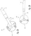
- FIG. 1 c is a perspective view of the male electrical connector of FIG. 1 a according to some embodiments;
- FIG. 1 d is a cross section view of the flat electrical conductor of the male electrical connector along the section line 1 d - 1 d of FIG. 1 a according to some embodiments;
- FIG. 2 a is a top view of a female electrical connector according to some embodiments.
- FIG. 2 b is a cross-section side view of the female electrical connector of FIG. 2 a along the section line 2 b - 2 b of FIG. 2 a according to some embodiments;
- FIG. 2 c is a perspective view of the female electrical connector of FIG. 2 a according to some embodiments.
- FIG. 3 a is a top view of the male electrical connector of FIG. 1 a in a pre-engaged position and the female electrical connector of FIG. 2 a according to some embodiments;
- FIG. 3 b is a top view of the male electrical connector of FIG. 1 a rotated to an engaged position and the female electrical connector of FIG. 2 a according to some embodiments;
- FIG. 4 a is a top view of a male electrical connector according to some embodiments.
- FIG. 4 b is a side view of the male electrical connector of FIG. 4 a according to some embodiments.
- FIG. 4 c is a perspective view of the male electrical connector of FIG. 4 a according to some embodiments.
- FIG. 4 d is a cross section view of the flat electrical conductor of the male electrical connector along the section line 4 d - 4 d of FIG. 4 c according to some embodiments.
- a low-profile electrical connector assembly in which a male terminal is locked into a female terminal by twisting a pivot point on the male terminal around a mating pivot point on the female terminal is presented herein.
- the male terminal has contact arms extending from its pivot point that are received in receptacles of the female terminal as the male terminal is twisted about the pivot points, thus locking the male terminal to the female terminal.
- the electrical connector assembly is particularly suited for making high current electrical connections between a wire attached to the male terminal and an on-glass conductive trace to which the female terminal is soldered, such as those used in automotive window defroster circuits.
- FIGS. 1 a - 1 d illustrate a non-limiting example of a male electrical terminal 100 of the electrical connector assembly.
- the male terminal 100 has a first pivot feature 102 and a pair of contact arms 104 extending from the first pivot feature 102 .
- the male terminal 100 also includes a wire attachment portion 106 extending from the first pivot feature 102 .
- the wire attachment portion 106 has a pair of crimp wings 108 that are configured to attach the male terminal 100 to a wire electrical cable 10 as shown in FIGS. 3 a - 3 b .
- the first pivot feature 102 shown in FIGS. 1 a - 1 c is a circular aperture extending though the male terminal 100 .
- the pair of contact arms 104 extend from the first pivot feature 102 at an angle of about 105 degrees from the centerline of the wire attachment portion 106 and 150 degrees from each other.
- the contact arms 104 define contact projections 110 extending from a location near the free ends 112 of the contact arms 104 .
- the contact projections 110 have a spherical sector shape that is less than or equal to a hemisphere.
- the contact arms 104 also define stop features 114 extending perpendicularly from the contact arms 104 and located proximate the free ends 112 of the contact arms 104 .
- the stop feature 114 on one contact arm 104 is located on an opposite side of the stop feature 114 of the other contact arm 104 .
- the male terminal 100 may be formed from a sheet of metal, e.g., a tin-plated copper sheet, by stamping, punching, blanking, bending, and embossing methods well known to those skilled in the art.
- FIGS. 2 a - 2 c illustrate a non-limiting example of a female electrical terminal 200 of the electrical connector assembly.
- the female terminal 200 has a base plate 202 that defines a second pivot features 204 that is configured to mate with the first pivot feature 102 of the male terminal 100 and allow the male terminal 100 to pivot around the second pivot feature 204 .
- the female terminal 200 also includes a pair of receptacle features 206 that are configured to receive the free ends 112 of the contact arms 104 as the first pivot feature 102 engages the second pivot feature 204 and the contact arms 104 are twisted or rotated around the first and second pivot features, 102 , 204 .
- the base plate 202 has a generally planar and circular shape.
- the second pivot feature 204 projects from the base plate 202 and has a spherical sector shape that is less than or equal to a hemisphere.
- the receptacle features 206 are in the form of J-shaped tabs 208 extending from the edges of the base plate 202 .
- the tabs 208 form a gap 210 with the base plate 202 in which the free ends 112 of the contact arms 104 are received.
- the tabs 208 define contact indentations 212 that are configured to receive the contact projections 110 .
- the contact indentations 212 are formed by circular apertures extending through the tabs 208 .
- the base plate 202 also includes a layer of solder 214 on the side of the base plate 202 opposite the second pivot feature 204 that is used to attach the female terminal 200 to a conductive trace, e.g. a defroster circuit on an automotive glass window (not shown).
- the female terminal 200 may be formed from a sheet of metal, e.g., a tin-plated copper sheet, by stamping, punching, blanking, bending, and embossing methods well known to those skilled in the art. This combination of male terminal 100 and female terminal 200 provide the benefits of higher current carrying capability than the prior post and cup sockets and so may be used in higher current applications, such as window defrosters.
- FIGS. 3 a - 3 b show the process of connecting the male terminal 100 to the female terminal 200 .
- the second pivot feature 204 of the female terminal 200 is received within the first pivot feature 102 of the male terminal 100 while the free ends 112 of the contact arms 104 are offset from the receptacle features 206 .
- the male terminal 100 is then rotated in a clockwise direction relative to the female terminal 200 to the engaged position 304 shown in FIG.
- the contact projections 110 on the contact arms 104 are disposed within the contact indentations 212 of the receptacle features 206 and the stop features 114 are in contact or engaged with the receptacle feature 206 , thereby inhibiting further rotation of the male terminal 100 .
- the contact projections 110 will make contact with the tabs 208 and push them outwardly until the contact projections 110 are seated within the contact indentations 212 at which point the tabs 208 will flex inwardly return to their original position.
- the contact arms 104 , contact projections 110 , tabs 208 , and contact indentations 212 are sized, shaped, and arranged to produce a normal force between the male and female terminals when in the engaged position of FIG. 3 b.
- the engagement of the contact projections 110 with the contact indentations 212 and the contact of the stop features 114 with the receptacle features 206 provides tactile feedback to an assembler that the male terminal 100 is fully engaged and electrically connected with the female terminal 200 .
- FIGS. 4 a - 4 d An alternative embodiment of the male terminal 400 is shown in FIGS. 4 a - 4 d in which the first pivot feature 402 is in the form of a hollow spherical sector.
- Other alternative embodiments of the electrical connector assembly may be envisioned in which the male terminal is rotated counterclockwise relative to the female terminal, the first pivot feature is received within the second pivot feature, the second pivot feature has a cylindrical shape, or the contact arms define spring features to engage the receptacle feature.
- Yet other embodiments may be envisioned for use with printed circuit boards or including a mounting stud protecting from the base plate of the female terminal.
Landscapes
- Coupling Device And Connection With Printed Circuit (AREA)
- Details Of Connecting Devices For Male And Female Coupling (AREA)
Abstract
Description
Claims (14)
Priority Applications (2)
| Application Number | Priority Date | Filing Date | Title |
|---|---|---|---|
| US17/484,016 US11705658B2 (en) | 2020-10-02 | 2021-09-24 | Twist-lock electrical connector assembly |
| CN202111157849.6A CN114389057B (en) | 2020-10-02 | 2021-09-30 | Twist-lock electrical connector assembly |
Applications Claiming Priority (2)
| Application Number | Priority Date | Filing Date | Title |
|---|---|---|---|
| US202063086893P | 2020-10-02 | 2020-10-02 | |
| US17/484,016 US11705658B2 (en) | 2020-10-02 | 2021-09-24 | Twist-lock electrical connector assembly |
Publications (2)
| Publication Number | Publication Date |
|---|---|
| US20220109261A1 US20220109261A1 (en) | 2022-04-07 |
| US11705658B2 true US11705658B2 (en) | 2023-07-18 |
Family
ID=80932594
Family Applications (1)
| Application Number | Title | Priority Date | Filing Date |
|---|---|---|---|
| US17/484,016 Active US11705658B2 (en) | 2020-10-02 | 2021-09-24 | Twist-lock electrical connector assembly |
Country Status (2)
| Country | Link |
|---|---|
| US (1) | US11705658B2 (en) |
| CN (1) | CN114389057B (en) |
Citations (7)
| Publication number | Priority date | Publication date | Assignee | Title |
|---|---|---|---|---|
| US2787693A (en) * | 1953-06-24 | 1957-04-02 | Continental Radiant Glass Heat | Electrical connectors |
| US3514740A (en) * | 1968-03-04 | 1970-05-26 | John Richard Filson | Wire-end connector structure |
| US5897406A (en) * | 1997-08-15 | 1999-04-27 | Molex Incorporated | Electrical terminal for glass sheets |
| US6039616A (en) | 1998-11-25 | 2000-03-21 | Antaya Technologies Corporation | Circular electrical connector |
| US6475043B2 (en) | 1998-11-25 | 2002-11-05 | Antaya Technologies Corporation | Circular electrical connector |
| US6520812B1 (en) | 2000-08-30 | 2003-02-18 | Antaya Technologies Corporation | Connector terminal with resilient contacts |
| US7160157B1 (en) * | 2006-03-17 | 2007-01-09 | Yazaki North America, Inc. | Twist-lock terminal connection system |
Family Cites Families (3)
| Publication number | Priority date | Publication date | Assignee | Title |
|---|---|---|---|---|
| US2977567A (en) * | 1944-03-31 | 1961-03-28 | Burndy Corp | Separable clasp connector |
| US5865638A (en) * | 1995-12-21 | 1999-02-02 | Alcoa Fujikura Ltd. | Electrical connector |
| JP4922898B2 (en) * | 2007-11-06 | 2012-04-25 | 株式会社オートネットワーク技術研究所 | Grounding terminal bracket and grounding terminal bracket fixing structure |
-
2021
- 2021-09-24 US US17/484,016 patent/US11705658B2/en active Active
- 2021-09-30 CN CN202111157849.6A patent/CN114389057B/en active Active
Patent Citations (18)
| Publication number | Priority date | Publication date | Assignee | Title |
|---|---|---|---|---|
| US2787693A (en) * | 1953-06-24 | 1957-04-02 | Continental Radiant Glass Heat | Electrical connectors |
| US3514740A (en) * | 1968-03-04 | 1970-05-26 | John Richard Filson | Wire-end connector structure |
| US5897406A (en) * | 1997-08-15 | 1999-04-27 | Molex Incorporated | Electrical terminal for glass sheets |
| US6599156B2 (en) | 1998-11-25 | 2003-07-29 | Antaya Technologies Corporation | Circular electrical connector |
| US7083481B2 (en) | 1998-11-25 | 2006-08-01 | Antaya Technologies Corporation | Circular electrical connector |
| US6475043B2 (en) | 1998-11-25 | 2002-11-05 | Antaya Technologies Corporation | Circular electrical connector |
| US7553204B2 (en) | 1998-11-25 | 2009-06-30 | Antaya Technologies Corporation | Circular electrical connector |
| US6599157B2 (en) | 1998-11-25 | 2003-07-29 | Antaya Technologies Corporation | Circular electrical connector |
| US6039616A (en) | 1998-11-25 | 2000-03-21 | Antaya Technologies Corporation | Circular electrical connector |
| US7371083B2 (en) | 1998-11-25 | 2008-05-13 | Antaya Technologies Corporation | Circular electrical connector |
| US7226299B2 (en) | 1998-11-25 | 2007-06-05 | Antaya Technologies Corporation | Circular electrical connector |
| US6780071B2 (en) | 1998-11-25 | 2004-08-24 | Antaya Technologies Corporation | Circular electrical connector |
| US6945831B2 (en) | 1998-11-25 | 2005-09-20 | Antaya Technologies Corporation | Circular electrical connector |
| US6249966B1 (en) | 1998-11-25 | 2001-06-26 | Antaya Technologies Corporation | Method of forming a circular electrical connector |
| US6676455B2 (en) | 2000-08-30 | 2004-01-13 | Antaya Technologies Corporation | Connector terminal with resilient contacts |
| US6607409B2 (en) | 2000-08-30 | 2003-08-19 | Antaya Technologies Corporation | Connector terminal with resilient contacts |
| US6520812B1 (en) | 2000-08-30 | 2003-02-18 | Antaya Technologies Corporation | Connector terminal with resilient contacts |
| US7160157B1 (en) * | 2006-03-17 | 2007-01-09 | Yazaki North America, Inc. | Twist-lock terminal connection system |
Also Published As
| Publication number | Publication date |
|---|---|
| US20220109261A1 (en) | 2022-04-07 |
| CN114389057B (en) | 2025-08-08 |
| CN114389057A (en) | 2022-04-22 |
Similar Documents
| Publication | Publication Date | Title |
|---|---|---|
| US5897406A (en) | Electrical terminal for glass sheets | |
| US6368154B1 (en) | Shielded electrical connector with ground contact spring | |
| US4718854A (en) | Low profile press fit connector | |
| US3365694A (en) | Connector means | |
| CN102714369B (en) | Power contacts | |
| JP3415934B2 (en) | Electrical terminal | |
| EP0112144B1 (en) | Electrical connector for flat flexible cable | |
| US8562374B2 (en) | Harness connector | |
| CN114006188B (en) | Coaxial electrical connector | |
| US10840611B1 (en) | Electrical terminal and method of forming same | |
| US12334660B2 (en) | Electrical terminal for flat flexible cables | |
| US6932659B1 (en) | Terminal with card edge locking provisions | |
| US4515422A (en) | Pin receptacle intended for mounting in a circuit board | |
| US9331413B2 (en) | Dual thickness double-ended male blade terminal | |
| US11705658B2 (en) | Twist-lock electrical connector assembly | |
| US10950965B2 (en) | Contact element arrangement | |
| US20060205267A1 (en) | Electrical connector and method of producing same | |
| US11984689B2 (en) | Conductive housing for connector and connector comprising the same | |
| EP3863119A1 (en) | Electrical terminal and method of forming same | |
| US7972147B2 (en) | Connector apparatus | |
| US6341978B1 (en) | Press-connecting terminal | |
| US12512610B2 (en) | Electronic device and contact element for use in an electronic device | |
| EP2859622B1 (en) | Terminal connection structure | |
| US12316062B2 (en) | Connecting apparatus and also assembly and electronic device | |
| KR20180031468A (en) | Press-fit type electric terminal structure |
Legal Events
| Date | Code | Title | Description |
|---|---|---|---|
| FEPP | Fee payment procedure |
Free format text: ENTITY STATUS SET TO UNDISCOUNTED (ORIGINAL EVENT CODE: BIG.); ENTITY STATUS OF PATENT OWNER: LARGE ENTITY |
|
| STPP | Information on status: patent application and granting procedure in general |
Free format text: DOCKETED NEW CASE - READY FOR EXAMINATION |
|
| AS | Assignment |
Owner name: APTIV TECHNOLOGIES LIMITED, BARBADOS Free format text: ASSIGNMENT OF ASSIGNORS INTEREST;ASSIGNORS:FOLGER, TYLER;MARTINS, DAVID BARROS;LUCCI, MARCO M.;AND OTHERS;SIGNING DATES FROM 20210917 TO 20210924;REEL/FRAME:061252/0325 |
|
| STPP | Information on status: patent application and granting procedure in general |
Free format text: NON FINAL ACTION MAILED |
|
| STPP | Information on status: patent application and granting procedure in general |
Free format text: RESPONSE TO NON-FINAL OFFICE ACTION ENTERED AND FORWARDED TO EXAMINER |
|
| STCF | Information on status: patent grant |
Free format text: PATENTED CASE |
|
| STCF | Information on status: patent grant |
Free format text: PATENTED CASE |
|
| AS | Assignment |
Owner name: APTIV TECHNOLOGIES (2) S.A R.L., LUXEMBOURG Free format text: ENTITY CONVERSION;ASSIGNOR:APTIV TECHNOLOGIES LIMITED;REEL/FRAME:066746/0001 Effective date: 20230818 Owner name: APTIV TECHNOLOGIES AG, SWITZERLAND Free format text: ASSIGNMENT OF ASSIGNORS INTEREST;ASSIGNOR:APTIV MANUFACTURING MANAGEMENT SERVICES S.A R.L.;REEL/FRAME:066551/0219 Effective date: 20231006 Owner name: APTIV MANUFACTURING MANAGEMENT SERVICES S.A R.L., LUXEMBOURG Free format text: MERGER;ASSIGNOR:APTIV TECHNOLOGIES (2) S.A R.L.;REEL/FRAME:066566/0173 Effective date: 20231005 |