US11692397B2 - Directional well trajectory control method based on drill pipe drive - Google Patents
Directional well trajectory control method based on drill pipe drive Download PDFInfo
- Publication number
- US11692397B2 US11692397B2 US17/241,591 US202117241591A US11692397B2 US 11692397 B2 US11692397 B2 US 11692397B2 US 202117241591 A US202117241591 A US 202117241591A US 11692397 B2 US11692397 B2 US 11692397B2
- Authority
- US
- United States
- Prior art keywords
- angle
- control
- parameters
- well
- well trajectory
- Prior art date
- Legal status (The legal status is an assumption and is not a legal conclusion. Google has not performed a legal analysis and makes no representation as to the accuracy of the status listed.)
- Active, expires
Links
- 238000000034 method Methods 0.000 title claims abstract description 48
- 238000005553 drilling Methods 0.000 claims abstract description 46
- 239000012530 fluid Substances 0.000 claims description 27
- 238000001514 detection method Methods 0.000 claims description 14
- 230000008569 process Effects 0.000 abstract description 13
- 238000004140 cleaning Methods 0.000 abstract description 3
- 238000011161 development Methods 0.000 abstract description 3
- 230000000694 effects Effects 0.000 abstract description 3
- 230000035515 penetration Effects 0.000 abstract description 3
- 238000010586 diagram Methods 0.000 description 12
- 238000004364 calculation method Methods 0.000 description 11
- 230000007246 mechanism Effects 0.000 description 10
- 230000005540 biological transmission Effects 0.000 description 9
- 238000005259 measurement Methods 0.000 description 8
- 230000008878 coupling Effects 0.000 description 7
- 238000010168 coupling process Methods 0.000 description 7
- 238000005859 coupling reaction Methods 0.000 description 7
- 238000007789 sealing Methods 0.000 description 6
- 238000004422 calculation algorithm Methods 0.000 description 5
- 238000009434 installation Methods 0.000 description 5
- 230000008859 change Effects 0.000 description 4
- 238000004891 communication Methods 0.000 description 4
- 230000000630 rising effect Effects 0.000 description 4
- 230000001133 acceleration Effects 0.000 description 3
- 230000009471 action Effects 0.000 description 3
- 230000005484 gravity Effects 0.000 description 3
- 238000007781 pre-processing Methods 0.000 description 3
- 230000015572 biosynthetic process Effects 0.000 description 2
- 238000006073 displacement reaction Methods 0.000 description 2
- 238000005755 formation reaction Methods 0.000 description 2
- 230000014509 gene expression Effects 0.000 description 2
- 238000009499 grossing Methods 0.000 description 2
- 238000012544 monitoring process Methods 0.000 description 2
- 210000002445 nipple Anatomy 0.000 description 2
- 230000002093 peripheral effect Effects 0.000 description 2
- 230000000717 retained effect Effects 0.000 description 2
- 229910000831 Steel Inorganic materials 0.000 description 1
- 238000006243 chemical reaction Methods 0.000 description 1
- 238000012937 correction Methods 0.000 description 1
- 238000000354 decomposition reaction Methods 0.000 description 1
- 230000007547 defect Effects 0.000 description 1
- 238000000605 extraction Methods 0.000 description 1
- 238000007689 inspection Methods 0.000 description 1
- 238000012423 maintenance Methods 0.000 description 1
- 238000012545 processing Methods 0.000 description 1
- 230000008439 repair process Effects 0.000 description 1
- 239000011435 rock Substances 0.000 description 1
- 230000035945 sensitivity Effects 0.000 description 1
- 239000010959 steel Substances 0.000 description 1
- 230000002194 synthesizing effect Effects 0.000 description 1
Images


Classifications
-
- E—FIXED CONSTRUCTIONS
- E21—EARTH OR ROCK DRILLING; MINING
- E21B—EARTH OR ROCK DRILLING; OBTAINING OIL, GAS, WATER, SOLUBLE OR MELTABLE MATERIALS OR A SLURRY OF MINERALS FROM WELLS
- E21B7/00—Special methods or apparatus for drilling
- E21B7/04—Directional drilling
- E21B7/06—Deflecting the direction of boreholes
- E21B7/062—Deflecting the direction of boreholes the tool shaft rotating inside a non-rotating guide travelling with the shaft
-
- E—FIXED CONSTRUCTIONS
- E21—EARTH OR ROCK DRILLING; MINING
- E21B—EARTH OR ROCK DRILLING; OBTAINING OIL, GAS, WATER, SOLUBLE OR MELTABLE MATERIALS OR A SLURRY OF MINERALS FROM WELLS
- E21B44/00—Automatic control systems specially adapted for drilling operations, i.e. self-operating systems which function to carry out or modify a drilling operation without intervention of a human operator, e.g. computer-controlled drilling systems; Systems specially adapted for monitoring a plurality of drilling variables or conditions
-
- E—FIXED CONSTRUCTIONS
- E21—EARTH OR ROCK DRILLING; MINING
- E21B—EARTH OR ROCK DRILLING; OBTAINING OIL, GAS, WATER, SOLUBLE OR MELTABLE MATERIALS OR A SLURRY OF MINERALS FROM WELLS
- E21B7/00—Special methods or apparatus for drilling
- E21B7/04—Directional drilling
-
- E—FIXED CONSTRUCTIONS
- E21—EARTH OR ROCK DRILLING; MINING
- E21B—EARTH OR ROCK DRILLING; OBTAINING OIL, GAS, WATER, SOLUBLE OR MELTABLE MATERIALS OR A SLURRY OF MINERALS FROM WELLS
- E21B44/00—Automatic control systems specially adapted for drilling operations, i.e. self-operating systems which function to carry out or modify a drilling operation without intervention of a human operator, e.g. computer-controlled drilling systems; Systems specially adapted for monitoring a plurality of drilling variables or conditions
- E21B44/02—Automatic control of the tool feed
-
- E—FIXED CONSTRUCTIONS
- E21—EARTH OR ROCK DRILLING; MINING
- E21B—EARTH OR ROCK DRILLING; OBTAINING OIL, GAS, WATER, SOLUBLE OR MELTABLE MATERIALS OR A SLURRY OF MINERALS FROM WELLS
- E21B47/00—Survey of boreholes or wells
- E21B47/02—Determining slope or direction
- E21B47/022—Determining slope or direction of the borehole, e.g. using geomagnetism
-
- E—FIXED CONSTRUCTIONS
- E21—EARTH OR ROCK DRILLING; MINING
- E21B—EARTH OR ROCK DRILLING; OBTAINING OIL, GAS, WATER, SOLUBLE OR MELTABLE MATERIALS OR A SLURRY OF MINERALS FROM WELLS
- E21B47/00—Survey of boreholes or wells
- E21B47/02—Determining slope or direction
- E21B47/024—Determining slope or direction of devices in the borehole
-
- E—FIXED CONSTRUCTIONS
- E21—EARTH OR ROCK DRILLING; MINING
- E21B—EARTH OR ROCK DRILLING; OBTAINING OIL, GAS, WATER, SOLUBLE OR MELTABLE MATERIALS OR A SLURRY OF MINERALS FROM WELLS
- E21B47/00—Survey of boreholes or wells
- E21B47/12—Means for transmitting measuring-signals or control signals from the well to the surface, or from the surface to the well, e.g. for logging while drilling
- E21B47/14—Means for transmitting measuring-signals or control signals from the well to the surface, or from the surface to the well, e.g. for logging while drilling using acoustic waves
- E21B47/18—Means for transmitting measuring-signals or control signals from the well to the surface, or from the surface to the well, e.g. for logging while drilling using acoustic waves through the well fluid, e.g. mud pressure pulse telemetry
-
- E—FIXED CONSTRUCTIONS
- E21—EARTH OR ROCK DRILLING; MINING
- E21B—EARTH OR ROCK DRILLING; OBTAINING OIL, GAS, WATER, SOLUBLE OR MELTABLE MATERIALS OR A SLURRY OF MINERALS FROM WELLS
- E21B49/00—Testing the nature of borehole walls; Formation testing; Methods or apparatus for obtaining samples of soil or well fluids, specially adapted to earth drilling or wells
- E21B49/003—Testing the nature of borehole walls; Formation testing; Methods or apparatus for obtaining samples of soil or well fluids, specially adapted to earth drilling or wells by analysing drilling variables or conditions
Definitions
- the disclosure relates to directional well trajectory control method based on drill pipe drive.
- Directional well trajectory control tools based on drill pipe drive use the rotation of the drill pipe as the driving force of the bias mechanism. Under the action of the bias mechanism, the tool spindle is forced to produce an offset, which causes the drill to have an inclination with the axis of the borehole to perform directional drilling.
- Directional well trajectory control tools include an eccentric mechanism and a deceleration device, an electromagnetic clutch, a sensor and a controller connected to the eccentric mechanism, the biasing power of well trajectory control tools is provided by a drill pipe.
- the eccentric mechanism is composed of an inner ring and an outer ring. The inner ring is nested in the inner hole of the outer ring, and the main shaft is nested in the inner hole of the inner ring.
- the matched well trajectory control method is to down-transmit control signals to the controller through drilling fluid pulses, so that the controller controls the action of the electromagnetic clutch to control the actions of the inner ring and the outer ring of the eccentric mechanism, thereby realizing deflection, which can realize three-dimensional well trajectory control during drilling operations without frequent trips.
- the existing control method has defects in the control process, such as the inability in close-loop control, the inability to remove interference signals, etc., and often cannot accurately control well trajectory.
- Well trajectory has certain deviations, so it is necessary to improve the existing control method to enable precise control of well trajectory.
- the directional well trajectory control method based on the drill pipe drive provided by this disclosure can accurately control the well trajectory through the reasonable setting of the decoding method, the bias vector calculation method, and the sensor placement position. Through the closed loop of the deflection angle and the measured deflection angle, the well trajectory can be further accurately controlled to solve the problem that the existing control method cannot accurately control the well trajectory.
- a directional well trajectory control method based on drill pipe drive including the following steps:
- the wellbore parameters are coded by the method of dynamic incremental coding of steering parameters, after the coding is completed, the wellbore parameters are down-transmitted to the tool controller through drilling fluid pulses;
- the tool controller After the tool controller receives the drilling fluid pulse signal, it decodes the pulse signal through initial threshold determination, peak detection, and threshold update;
- the directional well trajectory control method based on drill pipe drive can achieve three-dimensional well trajectory control without frequent trips during drilling operations, and has a high penetration rate, good wellbore cleaning effect, well trajectory control accuracy, high flexibility, low tripping times, high borehole quality, high safety, etc., which is suitable for the development of special process wells such as medium-deep wells, ultra-deep wells, ultra-thin oil layer horizontal wells and unconventional oil and gas wells in China's complex oil and gas reservoirs.
- This method can also achieve precise control of well trajectory, and overcome the shortcomings of existing control methods that cannot achieve closed-loop control and cannot remove interference signals.
- FIG. 1 is a schematic diagram of this disclosure in a guided state
- FIG. 2 is a schematic diagram of the structure of a directional well trajectory control tool based on drill pipe drive
- FIG. 3 is a schematic diagram of the overall control scheme of this disclosure.
- FIG. 4 is a schematic diagram of the time sequence of the incremental coding of wellbore parameters of this disclosure
- FIG. 5 is a schematic diagram of the decoding process of parameters down-transmission according to this disclosure.
- FIG. 6 is a schematic diagram of the positional relationship between the preset point and the current point of this disclosure.
- FIG. 7 is a schematic diagram of the eccentric displacement of the main shaft of this disclosure.
- FIG. 8 is a schematic diagram of the well trajectory-oriented control algorithm of this disclosure.
- FIG. 9 is a schematic diagram of the closed-loop control principle of the rotation angle of the eccentric ring according to this disclosure.
- FIG. 10 is a schematic diagram of the installation of the angle transmission sensor of this disclosure.
- FIG. 11 is a schematic diagram of the measurement and control scheme of the pointing well trajectory control tool based on the drill pipe drive of this disclosure.
- a directional well trajectory control method based on drill pipe drive including the following steps:
- the overall control scheme of the directional well trajectory control is: the ground terminal includes a data acquisition and transmission unit, a ground calculation and analysis simulation center, and an instruction down-transmission unit; according to the data at the preset point and the current point, the ground terminal performs calculations, the orientation control command is down-transmitted to the MWD.
- the down-transmission of the well parameters mainly includes encoding and decoding, mainly adopts the dynamic incremental coding method of the guidance parameter; then the command is down-transmitted to the tool controller through the communication subsection, and the tool controller is based on the instruction and the measurement result of the attitude sensor to control the eccentric mechanism of the well trajectory control tool 9 to make the eccentric ring reach the specified position; the eccentric ring position sensor feeds back the current position and angle of the eccentric ring to the controller, and the controller compares the difference with the predetermined position values, makes the eccentric ring rotate again, and repeats until the deviation is within the required range; the drill pipe in the wellbore drives the drill to perform drilling, and at the same time provides power for the bias mechanism of the well trajectory control tool 9 ; the controller of the well trajectory control tool 9 is based on the control commands down-transmitted from the ground and the measurement data of the downhole sensors to control the well trajectory control tool to achieve guidance (referring to FIG. 1 ).
- the well trajectory control tool includes a mandrel 10 , an upper dynamic sealing device 11 , an upper cantilever bearing 12 , an inclinometer puppet 13 , an upper coupling 15 , an outer ring electromagnetic clutch 16 , an outer ring harmonic drive device 17 , an inner ring 18 , an outer ring 19 , an inner ring harmonic drive device 20 , an inner ring electromagnetic clutch 21 , a lower end coupling 22 , a lower end ball bearing 23 , a lower end dynamic sealing device 24 and a drill 9 ; the upper end of the drill string is connected with the drill pipe 5 , and the lower end is connected with the mandrel 10 ; the mandrel 10 is a hollow rotating shaft, which is the power source of the entire tool.
- the power of the mandrel 10 is provided by the upper drill pipe 5 ; the upper dynamic sealing device 11 is installed at the uppermost end of the tool; the lower end of the upper coupling 15 is installed with the outer ring electromagnetic clutch 16 , the outer ring harmonic drive device 17 , and the eccentric mechanism in sequence; the installation positions of the inner ring harmonic drive device 20 , the inner ring electromagnetic clutch 21 and the lower end coupling 22 are symmetric about eccentric mechanism with respect to the installation positions of outer ring harmonic drive device 17 , the outer ring electromagnetic clutch 16 and the upper coupling 15 , and their connection forms are the same; the lower end ball bearing 23 and the lower end dynamic sealing device 24 are installed at the bottom of the tool.
- the drilling steering parameter commands is down-transmitted along the drill string through drilling fluid pulses to the communication nipple at the bottom hole drill; the drilling fluid is modulated into pulse waves to flow in the drill string through coding and modulation, the bottom hole receiving end needs to use the corresponding decoding algorithm for decoding, so that the drilling fluid pulse information can be converted into steering commands for execution.
- the disclosure proposes a dynamic incremental value encoding method for directional drilling parameters to complete the encoding transmission process of the directional drilling parameters.
- the preset incremental positive and negative sign s and the difference relative to the previous overall data ⁇ d based on the previous data transmission, the subsequent data only needs to be transmitted ⁇ d s , which can be calculated and obtained through the formula (2-1).
- ⁇ d s s ⁇ d (2-1)
- the specific values can be calculated by substituting the last calculated value d1 and the incremental data value ⁇ d s into the formula (2-1).
- d 2 d 1 + d s (2-2)
- the incremental positive and negative sign s is set by the ground control unit that transmits the information.
- the use of dynamic incremental data is mainly to solve a large number of repeated data transmissions and reduce the length of pulse time occupied by data; the use of dynamic incremental value to transmit data can effectively reduce the amount of data transmission and improve the efficiency of the transmission system.
- the ground down-transmission parameters include well depth, well inclination, and azimuth
- the down-transmission data packets include: synchronization word, command type, azimuth, inclination, well depth and inspection code, on the ground, the data package is coded according to the coding rules in Table 1 with the multiple of drilling fluid unit pulse time T p .
- the duration of 7 pulses can be obtained, including t 1 , t 2 , t 3 , t 4 , t 5 , t 6 , t 7 , the low pulse duration t 1 is the length of the synchronization word, the high pulse duration t 2 represents the azimuth command type, and the low pulse The duration t 3 represents the azimuth value, the high pulse duration t 4 represents the inclination angle command type, the low pulse duration t 5 represents the inclination angle value, the high pulse duration t 6 represents the well depth, and the low pulse duration t 7 represents the check code.
- ⁇ represents the transmitted azimuth angle parameter
- ⁇ 1 is the last azimuth angle value
- ⁇ represents the transmitted well deviation angle parameter
- ⁇ 1 is the last well deviation angle value
- setting the maximum well depth increment 30 meters and calculating the footage value directly through the pulse time.
- ⁇ L represents the footage value in meters.
- the core of decoding is to identify the duration of a pulse, so it is necessary to find out the time points of the beginning and end of the pulse; and the pulse signal received by the bottom hole equipment contains a lot of interference information, and the pulse signal cannot be directly identified, so it is necessary to check the pulse signal.
- the down-transmission signal is preprocessed, and then the peak value of the incrementally coded drilling fluid pulse signal is identified, so as to determine the beginning and end of the pulse, and then determining the pulse duration, and finally decoding the ground transmission instruction through the encoding rule; the process of down-transmitting parameters decoding mainly includes pulse signal preprocessing and decoding.
- the first step of the preprocessing process is reading the real-time sampled pulse signal, and then performs denoising processing on it to see if there is a delay in the data. If there is no delay, smoothing is performed; If there is a delay, it is needed to repair the delay caused by denoising first, and then perform smoothing; the signal after preprocessing is a standard pulse signal, identifying the peak value combined with the dynamic differential threshold method, determining the pulse duration, and finally calculating the corresponding down-transmitting parameters according to the instruction time to complete the decoding ( FIG. 5 ).
- the peak value of the drilling fluid pulse signal is dynamically extracted, and the method of symbolized signal approximate matching is applied according to the threshold value in the extraction process to detect the interference section of the drilling fluid pulse signal, which can effectively improve the peak value of the drilling fluid wave.
- the specific process of detection efficiency can be divided into initial threshold determination, drilling fluid pulse wave peak detection and threshold update.
- the bottom hole flow sensor is grouped by time period (for example: 5 groups) to detect the drilling fluid flow signal.
- time period for example: 5 groups
- the retained data is recorded as [d 1 , d 2 , d 3 ], where D is used to represent its arithmetic mean
- the upper limit of the initial amplitude threshold is calculated
- Peak value identifying assuming that any three consecutive points of the drilling fluid pulse signal curve are f i , f i+1 , f i+2 ; through f i+1 -f i >Th 1 and f i+2 -f i+1 >Th 1 , it can be judged whether f i+1 is on the falling edge of the drilling fluid pulse; through f i+1 -f i >Th 1 and f i+2 -f i+1 >Th 1 , it can be judged whether f i+1 is on the rising edge of the drilling fluid pulse; combined with the previous falling edge and rising edge judgment, If f i+1 satisfies
- f i+2 may be the valley pulse value point, and its amplitude value is recorded as ⁇ new ; adopting the amplitude threshold value to judge whether f i+2 is the pulse valley point, the judgment condition is
- Threshold update by continuously identifying new peaks and troughs of the drilling fluid pulse, the previous thresholds are replaced, and the next identifying is performed:
- the dynamic threshold method is adopted to analyze the amplitude value of the interference signal, and dynamically correcting the amplitude value of the interference signal, which can ensure that the drilling fluid pulse communication is more stable; after the peak value is identified, calculating various borehole parameters using Table 1 through the various durations of the code.
- the tool face angle and offset are calculated, specifically: the dogleg angle ⁇ can be calculated according to the spatial angle of the preset point and the current point, and the tool face angle ⁇ can be calculated, the calculation process (referring to FIG. 6 ) is:
- ⁇ is the difference between the azimuth angle of the preset point and the current point
- ⁇ is the difference between the preset point and the current point well angle
- ⁇ m is the average value of the preset point and the current point well angle
- ⁇ is the dog leg angle
- ⁇ TF is the general formula for calculating the tool face angle.
- the modulus of the combined bias vector that is, the magnitude of the combined eccentricity
- L 1 is the distance from the upper bearing to the eccentric ring
- L 2 is the distance from the lower bearing to the eccentric ring
- L is the distance between the two bearings
- L L 1 +L 2
- ⁇ is the dog leg angle, which is the angle between the drill axis and the tool axis
- is the offset value.
- the shell rotation angle ⁇ Due to the friction between the tool shell and the rock formation, the shell rotates, causing the actual tool face angle to deviate from the calculated tool face angle.
- the deviation value is the shell rotation angle ⁇ .
- the tool face angle ⁇ can be obtained from the previous calculation.
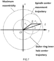
- the directional well trajectory control tool based on drill pipe drive can determine the offset vector according to the position parameters of the preset point and the current point when drilling, and decompose it into the offset vector on the inner eccentric ring and the outer eccentric ring, and finally transform it Into the rotation angle of the inner and outer eccentric ring.
- the schematic diagram of the eccentric displacement of the main shaft is shown in FIG. 7 .
- o is the center of the shell
- A is the center of the spindle
- B is the center of the inner hole of the outer ring
- e 1 is the eccentricity of the outer eccentric ring
- e 2 is the eccentricity of the inner eccentric ring
- e is the total eccentricity of the eccentric ring group.
- e x is the projection of e on the x-axis
- e y is the projection of e on the y-axis.
- the angles between e 1 , e 2 , e and the x-axis are ⁇ 1 , ⁇ 2 , and ⁇ (referring to FIG. 7 ).
- e e 1 2 + e 2 2 + 2 ⁇ ⁇ e 1 ⁇ e 2 ⁇ cos ⁇ ( ⁇ 2 - ⁇ 1 ) ( 4 ⁇ - ⁇ 3 )
- ⁇ arc ⁇ ⁇ tan ⁇ e 1 ⁇ sin ⁇ ⁇ ⁇ 1 + e 2 ⁇ sin ⁇ ⁇ ⁇ 2 e 1 ⁇ cos ⁇ ⁇ ⁇ 1 + e 2 ⁇ cos ⁇ ⁇ ⁇ 2 ( 4 ⁇ - ⁇ 4 )
- ⁇ 1 ⁇ ⁇ arccos ⁇ ( e 6 )
- ⁇ ⁇ 2 ⁇ ⁇ arccos ⁇ ( e 6 ) ( 4 ⁇ - ⁇ 5 )
- k 0 is the slope of the line connecting the initial point of the inner hole center of the outer ring and the origin of the coordinate
- k 1 is the slope of the line connecting the initial point of the spindle center and the origin of the coordinate
- k 4 is the slope of the target point and the origin line
- k 2 and k 3 are obtained by substituting k 0 and k 1 into the trajectory equation of the spindle center point; comparing the magnitude between ⁇ 20 and ⁇ 30 , if the same value is positive, take the smaller value; if the same value is negative, take the value with larger absolute value; if one is positive and the other is negative, take the positive one; turn the drill pipe into the positive direction; and because the value range of arctanx is between 0-180°, if the ⁇ ( ⁇ 20 or ⁇ 30 ) selected before is positive, the outer eccentric ring is rotated by ⁇ in the positive direction, and the inner eccentric ring is rotated by ⁇ 1 in the positive direction;
- the inner and outer ring rotation angles are obtained.
- the well trajectory directional control algorithm obtains the tool face angle and offset from the synthetic offset vector, which can calculate the given angle of the inner and outer eccentric ring, Combined with the measured value of the three-axis acceleration sensor and the angle sensor, the difference between the predetermined value and the predetermined value can be obtained; after the inner and outer loops move, the angle sensor will feedback the measurement result to the tool controller again to get the difference again, making the inner and outer loops act according to the difference, and keep looping until the difference meets the requirements.
- ⁇ r is the preset angle input of the eccentric ring; e is the deviation; u k is the input of the electromagnetic clutch, which controls the opening and closing of the electromagnetic clutch; u is the output of the electromagnetic clutch; ⁇ is the output of the eccentric ring angle, obtained by the angle sensor; According to the difference e between the preset angle ⁇ r and the angle output ⁇ , the controller controls the opening and closing of the electromagnetic clutch, and finally makes the eccentric ring act.
- the electromagnetic clutch used in this tool requires a starting voltage of +24v when starting, and only a maintenance voltage of 6v after starting. Based on the consideration of power consumption, PWM (Pulse Width Modulation) is used to control the switch of the electromagnetic clutch.
- the deviation between the angle detected by the sensor and the set angle is used as the control parameter of the eccentric ring rotation angle.
- the control accuracy of the entire closed-loop control is related to the detection accuracy, and the sensor detection accuracy is related to the performance and installation method of the sensor itself.
- the sensor adopts the differential installation method, so that the detection accuracy is controlled at 1°, which lays the foundation for the closed-loop control of the eccentric ring rotation angle (referring to FIG. 9 ).
- the working state of the electromagnetic clutch determines the rotation of the inner and outer rings. Therefore, under what circumstances the electromagnetic clutch is engaged and disconnected is of vital importance to the precise guidance of the entire system.
- the key factor determining the closing and opening of the electromagnetic clutch is the deviation e between the given angle and the measured value of the angle, but it is not necessary to engage the electromagnetic clutch as long as e>0. This requires a total of 5 conditions to determine the state of the electromagnetic clutch according to the difference e of the deviation and calculate the control of the battery clutch referring to Table 2.
- E 0 0 (OFF)
- E eccentric ring angle setting value—eccentric ring angle measured value
- deviation zero band ( ⁇ E 0 ) actual allowable deviation range value (based on experience, artificially set).
- X, Y, Z be the three-axis accelerometer coordinate system, where the Z axis is parallel to the axis of the guide tool and points to the bottom of the guide tool; the X axis and Y axis are both on the cross section of the instrument, and X points to the reference direction of the instrument; The Y axis is perpendicular to the X axis, and the three axes are orthogonal to each other.
- the tool face angle of the well trajectory control tool can be completed by a dedicated inclinometer sub: the calculation of the tool face angle in the inclinometer nipple only needs to measure the components in the three-axis direction of the tool coordinate system, according to these three acceleration components, the tool surface of the guiding tool can be calculated; therefore, the inclinometer sub is installed on the non-rotating shell; and because only one plane changes when the shell rotates, when the shell rotates, it is only needed to measure the component of the acceleration of gravity in the Z-axis direction, then the tool face angle can be obtained; the axis of the inclinometer pup is parallel to the high side of the tool's gravity direction (the initial state of the tool is not eccentric); the inclinometer pup is installed in the Z axis direction of the instrument coordinates (referring to FIG. 10 ).
- the mechanical angle of the entire measuring gear is 360°, and there are 45 pairs of teeth, which are connected with the eccentric ring through the positioning pin hole and rotate with the eccentric ring; the spindle passes through the center hole of the measuring gear.
- the hole size is slightly larger than the spindle size because the spindle will bend during the offset process; the angle sensor is installed on the non-rotating shell, and the Hall sensor KM116/1 is used to realize the eccentric ring angle measurement.
- the chip contains high-performance magnetic steel, magnetoresistive sensor and IC. It uses IC to complete the signal conversion function. When the magnetic line of force is shielded (shunt) and cannot reach the Hall IC, the output of the Hall IC jumps to a low level at this time.
- the frequency of the output current signal is proportional to the measured speed.
- the change range of the current signal is 7 ⁇ 14 mA; because its peripheral circuit is relatively simple, it is easy to equip with a secondary meter to measure the speed; it has strong anti-interference ability and directionality, it is not sensitive to axial vibration, and its working temperature range is wide up to ⁇ 40° C. ⁇ +150° C.; KMI16/1 sensor has the advantages of high sensitivity, wide measuring range, strong anti-interference ability, simple peripheral circuit, etc.; its volume is small, the maximum size is 8 mm ⁇ 6 mm ⁇ 21 mm, and it can be reliably fixed near the gear; In addition, there are electromagnetic interference (EMI) filters, voltage controllers and constant current sources inside the KMI16/1 sensor chip to ensure that its operating characteristics are not affected by external factors (referring to FIG. 10 ).
- EMI electromagnetic interference
- the ground control device sets the well trajectory parameters according to the needs, and the data is down-transmitted to the MWD controller; the MWD controller transmits the down-transmitted instructions to the tool controller through the communication terminal;
- the tool controller needs to control the rotation of the eccentric ring according to the received instructions and the detection data of the sensors; the rotation angle of the eccentric ring is measured by the eccentric ring angle sensor, and the relative rotation angle of the inner ring of the eccentric ring and the outer ring of the eccentric ring is decomposed and calculated according to the tool face angle and offset set by the ground monitoring system.
- Achieving precise control depends on precise measurement, that is, the control and detection of the eccentric ring angle are closely related; the control sub-section is an important part of completing the closed-loop control of the downhole eccentric ring angle, and the control sub-section is expected to be downloaded from the ground monitoring system.
- the value of the eccentric ring rotation angle is stored in the control unit, and the relative rotation of the eccentric ring is realized by controlling the pull-in of the electromagnetic clutch to make the spindle bend in the specified tool surface to achieve the purpose of skew.
- the deviation is used as a control parameter to control the electromagnetic clutch to achieve the purpose of controlling the rotation angle of the eccentric ring; during the drilling process, the shell of the tool will inevitably rotate and cause the deviation in the direction, the angle between the actual direction and the target direction is measured by the inclinometer sub-section installed on the shell to facilitate compensation and correction and reduce errors; the entire drilling system realizes double closed loops. Firstly, a small closed loop of the angle is realized, so that the rotation angle of the eccentric ring reaches the set angle; secondly, a large closed loop of underground engineering parameters is realized. Through the detection of well inclination, azimuth, and tool face angle, the eccentric ring rotation angle is recalculated, and the large closed loop is accurately controlled, and finally realizing the purpose of drilling according to the set trajectory.
- the directional well trajectory control method based on drill pipe drive can achieve three-dimensional well trajectory control without frequent trips during drilling operations, and has a high penetration rate, good wellbore cleaning effect, well trajectory control accuracy, high flexibility, low tripping times, high borehole quality, high safety, etc., which is suitable for the development of special process wells such as medium-deep wells, ultra-deep wells, ultra-thin oil layer horizontal wells and unconventional oil and gas wells in China's complex oil and gas reservoirs.
- This method can also achieve precise control of well trajectory, and overcome the shortcomings of existing control methods that cannot achieve closed-loop control and cannot remove interference signals.
Landscapes
- Engineering & Computer Science (AREA)
- Geology (AREA)
- Life Sciences & Earth Sciences (AREA)
- Mining & Mineral Resources (AREA)
- Physics & Mathematics (AREA)
- Environmental & Geological Engineering (AREA)
- Fluid Mechanics (AREA)
- General Life Sciences & Earth Sciences (AREA)
- Geochemistry & Mineralogy (AREA)
- Geophysics (AREA)
- Chemical & Material Sciences (AREA)
- Analytical Chemistry (AREA)
- Acoustics & Sound (AREA)
- Remote Sensing (AREA)
- Earth Drilling (AREA)
Abstract
Description
Δd s =s×Δd (2-1)
d 2 =d 1 +
| TABLE 1 |
| Dynamic incremental instruction coding format table |
| Maximum pulse time | |||
| Command name | Pluse type | (seconds) | Instruction description |
| Sync word | Low pulse | Tp | t1 = Tp |
| Azimuth command type | High pulse | 3 × Tp |
|
| Azimuth | Low pulse | 2 × Tp | Calculated from the value of t2 and t3 |
| Inclination angle command type | High pulse | 3 × Tp |
|
| Inclination angle | Low pulse | 2 × Tp | Calculated from the value of t4 and t6 |
| Well depth | High pulse | 2 × Tp | ΔL = (t6 = Tp) × 30/Tp |
| Check code | Low pulse | 2 × Tp |
|
If −360°<ϕ2−ϕ1<−180°, then α=αTF
If −180°<ϕ2−ϕ1<0°, then α=2π−αTF
If 0°<ϕ2−ϕ1<180°, then α=αTF
If −180°<ϕ2−ϕ1<360°, then α=2π−αTF
e x =e cos α=e 1 cos α1 +e 2 cos α2 (4-1)
e y =e sin α=e 1 sin α1 +e 2 sin α2 (4-2)
θ20=arc tan k 2−arctan k 0 (4-6)
θ30=arc tan k 3−arctan k 0 (4-7)
θ1=arc tan k 4−arctan k 1 (4-8)
| TABLE 2 |
| Electromagnetic clutch control algorithm |
| Electromagnetic clutch | ||||
| Eccentric state | control signal | |||
| E > 0 | |E| > E0 | 1 (ON) | |
| |E| < E0 | 0 (OFF) |
| E = 0 | 0 (OFF) |
| E < 0 | |E| < E0 | 0 (OFF) | ||
| |E| > E0 | 1 (ON) | |||
f
-
- 1 derrick
- 2 riser
- 3 sensors
- 4 controller
- 5 drill pipe
- 6 centralizer
- 7 MWD system
- 8 well trajectory control tool
- 9 drill
- 10 mandrel
- 11 upper dynamic sealing device
- 12 upper cantilever bearing
- 13 measurement and control short section
- 14 shell
- 15 upper coupling
- 16 outer ring electromagnetic clutch
- 17 outer ring harmonic drive
- 18 inner ring
- 19 outer ring
- 20 inner ring harmonic drive
- 21 inner ring electromagnetic clutch
- 22 lower end coupling
- 23 lower end ball bearing
- 24 lower end dynamic sealing device
Claims (1)
Applications Claiming Priority (3)
| Application Number | Priority Date | Filing Date | Title |
|---|---|---|---|
| CN202011097145X | 2020-10-14 | ||
| CN202011097145.X | 2020-10-14 | ||
| CN202011097145.XA CN112228035B (en) | 2020-10-14 | 2020-10-14 | Directional wellbore trajectory control method based on drill pipe drive |
Publications (2)
| Publication Number | Publication Date |
|---|---|
| US20220112769A1 US20220112769A1 (en) | 2022-04-14 |
| US11692397B2 true US11692397B2 (en) | 2023-07-04 |
Family
ID=74112779
Family Applications (1)
| Application Number | Title | Priority Date | Filing Date |
|---|---|---|---|
| US17/241,591 Active 2041-07-09 US11692397B2 (en) | 2020-10-14 | 2021-04-27 | Directional well trajectory control method based on drill pipe drive |
Country Status (2)
| Country | Link |
|---|---|
| US (1) | US11692397B2 (en) |
| CN (1) | CN112228035B (en) |
Families Citing this family (6)
| Publication number | Priority date | Publication date | Assignee | Title |
|---|---|---|---|---|
| CN113417631B (en) * | 2021-08-11 | 2023-05-02 | 中国石油大学(华东) | A system and method for transmitting ground commands of a rotary steerable tool |
| CN115788300B (en) * | 2022-12-19 | 2025-11-28 | 中国石油天然气集团有限公司 | Continuous rotary sliding drilling method |
| CN116122800B (en) * | 2023-03-06 | 2025-10-28 | 北京六合伟业科技股份有限公司 | A method and system for underground low-power encoding and decoding data transmission |
| CN116753243A (en) * | 2023-08-18 | 2023-09-15 | 凌远科技股份有限公司 | Dynamic directional rotary guiding force transmission bearing system |
| CN117780257B (en) * | 2024-02-27 | 2024-05-10 | 衡德(山东)勘察测绘有限公司 | Geological exploration data intelligent monitoring system and method based on big data |
| CN120026894B (en) * | 2025-01-22 | 2025-09-05 | 深地科学与工程云龙湖实验室 | A clustering trajectory correction method for directional drilling based on acceleration sensing |
Citations (2)
| Publication number | Priority date | Publication date | Assignee | Title |
|---|---|---|---|---|
| US20160326857A1 (en) * | 2014-02-20 | 2016-11-10 | Halliburton Energy Services, Inc. | Closed-loop speed/position control mechanism |
| US20160356089A1 (en) * | 2014-12-29 | 2016-12-08 | Halliburton Energy Services, Inc. | Mitigating stick-slip effects in rotary steerable tools |
Family Cites Families (8)
| Publication number | Priority date | Publication date | Assignee | Title |
|---|---|---|---|---|
| US8783382B2 (en) * | 2009-01-15 | 2014-07-22 | Schlumberger Technology Corporation | Directional drilling control devices and methods |
| CN102383777B (en) * | 2011-09-30 | 2014-07-02 | 中国海洋石油总公司 | Measuring and controlling device used for rotary steering drilling system and measuring and controlling method utilizing same |
| CN102493766B (en) * | 2011-11-30 | 2014-05-21 | 中国石油集团钻井工程技术研究院 | Borehole track control method and borehole track control system |
| CN102913131B (en) * | 2012-08-14 | 2016-08-10 | 中国石油大学(华东) | A Dynamic Pointing Rotary Steering Drilling Tool |
| CN103556945B (en) * | 2013-10-27 | 2015-07-01 | 长江大学 | High build-up rate well track control method |
| US9850712B2 (en) * | 2013-12-12 | 2017-12-26 | Schlumberger Technology Corporation | Determining drilling state for trajectory control |
| CN106761686B (en) * | 2016-12-13 | 2019-06-18 | 云南航天工程物探检测股份有限公司 | Self-adapting type intelligence well depth measuring device and measurement method |
| CN109653733B (en) * | 2018-11-22 | 2022-06-28 | 长江大学 | Downstreaming method and equipment for drilling steering parameters |
-
2020
- 2020-10-14 CN CN202011097145.XA patent/CN112228035B/en active Active
-
2021
- 2021-04-27 US US17/241,591 patent/US11692397B2/en active Active
Patent Citations (2)
| Publication number | Priority date | Publication date | Assignee | Title |
|---|---|---|---|---|
| US20160326857A1 (en) * | 2014-02-20 | 2016-11-10 | Halliburton Energy Services, Inc. | Closed-loop speed/position control mechanism |
| US20160356089A1 (en) * | 2014-12-29 | 2016-12-08 | Halliburton Energy Services, Inc. | Mitigating stick-slip effects in rotary steerable tools |
Also Published As
| Publication number | Publication date |
|---|---|
| CN112228035B (en) | 2024-04-30 |
| US20220112769A1 (en) | 2022-04-14 |
| CN112228035A (en) | 2021-01-15 |
Similar Documents
| Publication | Publication Date | Title |
|---|---|---|
| US11692397B2 (en) | Directional well trajectory control method based on drill pipe drive | |
| US11035218B2 (en) | Advanced steering tool system, method and apparatus | |
| US11118442B2 (en) | Boring tool tracking fundamentally based on drill string length, pitch and roll | |
| CN105041212B (en) | A kind of rotary steerable drilling control system and its control method | |
| CN103556945B (en) | High build-up rate well track control method | |
| US9689249B2 (en) | Automating downhole drilling using wellbore profile energy and shape | |
| US8694257B2 (en) | Method for determining uncertainty with projected wellbore position and attitude | |
| CN104453714B (en) | A kind of control method of rotary steerable tool | |
| CN104499940B (en) | A kind of full rotation directional type steering tool and guidance method | |
| CN104453713A (en) | Method for controlling well track by rotary steering tool | |
| WO2015161209A1 (en) | Automated sliding drilling | |
| EP1644612B1 (en) | Determination of the orientation and/or position of the downhole device | |
| CN105089611A (en) | Continuous measuring device for space attitude of bottom drilling tool | |
| CN202391408U (en) | Anti-collision range unit based on alternating magnetic field measurement | |
| CN113756717A (en) | Rotary guide device | |
| CN109915116A (en) | Magnetic surveys offset well anti-collision method and device with probing | |
| CN118933708A (en) | Oil drilling trajectory dynamic control method and device | |
| CN205047212U (en) | Continuous measuring device of bottom drilling tool space gesture | |
| US10900346B2 (en) | Azimuth determination while rotating | |
| CN212837586U (en) | a rotary guide | |
| CN207296994U (en) | A kind of DS-MWD wireless drillings measuring system |
Legal Events
| Date | Code | Title | Description |
|---|---|---|---|
| AS | Assignment |
Owner name: YANGTZE UNIVERSITY, CHINA Free format text: ASSIGNMENT OF ASSIGNORS INTEREST;ASSIGNORS:FENG, DING;ZHANG, HONG;WANG, PENG;AND OTHERS;REEL/FRAME:056054/0525 Effective date: 20210318 |
|
| FEPP | Fee payment procedure |
Free format text: ENTITY STATUS SET TO UNDISCOUNTED (ORIGINAL EVENT CODE: BIG.); ENTITY STATUS OF PATENT OWNER: SMALL ENTITY |
|
| FEPP | Fee payment procedure |
Free format text: ENTITY STATUS SET TO SMALL (ORIGINAL EVENT CODE: SMAL); ENTITY STATUS OF PATENT OWNER: SMALL ENTITY |
|
| STPP | Information on status: patent application and granting procedure in general |
Free format text: DOCKETED NEW CASE - READY FOR EXAMINATION |
|
| STPP | Information on status: patent application and granting procedure in general |
Free format text: NON FINAL ACTION MAILED |
|
| STPP | Information on status: patent application and granting procedure in general |
Free format text: RESPONSE TO NON-FINAL OFFICE ACTION ENTERED AND FORWARDED TO EXAMINER |
|
| STCF | Information on status: patent grant |
Free format text: PATENTED CASE |