US11683465B2 - Stereo illumination - Google Patents
Stereo illumination Download PDFInfo
- Publication number
- US11683465B2 US11683465B2 US16/747,200 US202016747200A US11683465B2 US 11683465 B2 US11683465 B2 US 11683465B2 US 202016747200 A US202016747200 A US 202016747200A US 11683465 B2 US11683465 B2 US 11683465B2
- Authority
- US
- United States
- Prior art keywords
- light source
- camera
- light
- source set
- imaging device
- Prior art date
- Legal status (The legal status is an assumption and is not a legal conclusion. Google has not performed a legal analysis and makes no representation as to the accuracy of the status listed.)
- Active, expires
Links
Images


Classifications
-
- H—ELECTRICITY
- H04—ELECTRIC COMMUNICATION TECHNIQUE
- H04N—PICTORIAL COMMUNICATION, e.g. TELEVISION
- H04N13/00—Stereoscopic video systems; Multi-view video systems; Details thereof
- H04N13/20—Image signal generators
- H04N13/204—Image signal generators using stereoscopic image cameras
- H04N13/246—Calibration of cameras
-
- H—ELECTRICITY
- H04—ELECTRIC COMMUNICATION TECHNIQUE
- H04N—PICTORIAL COMMUNICATION, e.g. TELEVISION
- H04N13/00—Stereoscopic video systems; Multi-view video systems; Details thereof
- H04N13/20—Image signal generators
- H04N13/204—Image signal generators using stereoscopic image cameras
- H04N13/239—Image signal generators using stereoscopic image cameras using two 2D image sensors having a relative position equal to or related to the interocular distance
-
- H—ELECTRICITY
- H04—ELECTRIC COMMUNICATION TECHNIQUE
- H04N—PICTORIAL COMMUNICATION, e.g. TELEVISION
- H04N13/00—Stereoscopic video systems; Multi-view video systems; Details thereof
- H04N13/20—Image signal generators
- H04N13/204—Image signal generators using stereoscopic image cameras
- H04N13/254—Image signal generators using stereoscopic image cameras in combination with electromagnetic radiation sources for illuminating objects
-
- H—ELECTRICITY
- H04—ELECTRIC COMMUNICATION TECHNIQUE
- H04N—PICTORIAL COMMUNICATION, e.g. TELEVISION
- H04N23/00—Cameras or camera modules comprising electronic image sensors; Control thereof
- H04N23/56—Cameras or camera modules comprising electronic image sensors; Control thereof provided with illuminating means
-
- H—ELECTRICITY
- H04—ELECTRIC COMMUNICATION TECHNIQUE
- H04N—PICTORIAL COMMUNICATION, e.g. TELEVISION
- H04N23/00—Cameras or camera modules comprising electronic image sensors; Control thereof
- H04N23/70—Circuitry for compensating brightness variation in the scene
- H04N23/74—Circuitry for compensating brightness variation in the scene by influencing the scene brightness using illuminating means
Definitions
- the subject matter disclosed herein relates to imaging devices and, in particular, to systems and methods for stereo illumination of a region that is to be captured by an imaging device.
- Stereoscopic imaging devices include at least two cameras separated from each other by a baseline in order to capture various images. Lighting for such systems can be difficult, as a lighting arrangement that is beneficial for one of the cameras can, due to the differences in their location and orientation, causing glare or shadows at the other cameras. Accordingly, there is a need for lighting systems for a stereoscopic imaging device that can be operated to the benefit of each camera of the imaging device.
- an imaging device includes a first camera, a first light source set at a periphery of the first camera for illuminating a region, a second camera separated from the first camera by a selected distance, a second light source set at a periphery of the second camera for illuminating the region, and a processor configured to operate the first light source set and the second light source set independently of each other to illuminate the region.
- a method of imaging a region includes: illuminating the region using a first light source set at a periphery of a first camera of an imaging device, obtaining a first image, illuminating the region using a second light source set at a periphery of a second camera of the imaging device, and obtaining a second image, wherein at least one of the first image and the second image includes an illumination effect.
- FIG. 1 A shows a frontal view of an imaging device of the present invention in an embodiment
- FIG. 1 B shows a top view of the imaging device of FIG. 1 A ;
- FIG. 1 C shows a perspective view of the second camera of the imaging device of FIG. 1 A showing a light barrier proximate to a lens of the second camera.
- FIG. 2 illustrates a light ray diagram indicating a direction of light ray propagation from LEDs of the imaging device
- FIG. 3 illustrates the angles of Table 1 for an arbitrary light ray
- FIG. 4 shows a projection of the LED light rays of FIG. 2 onto the x-z-plane
- FIG. 5 shows a projection of the LED light rays of FIG. 2 onto the y-z-plane
- FIGS. 6 A and 6 B shows calculated light distributions for a region in the positive z-direction for the imaging device
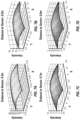
- FIGS. 7 A- 7 D show a calculated intensity distribution in x-y planes at various distances along the z-axis from the imaging device
- FIGS. 8 A and 8 B show calculated light distribution where only the left set of light sources is active
- FIGS. 9 A and 9 B show images of a background scenery that is used for illumination testing taken from the left camera of the imaging device and the right camera of the imaging device, respectively;
- FIGS. 10 A and 10 B show the same scenery as in FIGS. 9 A and 9 B , respectively, with illumination only by the second set of light sources;
- FIGS. 11 A and 11 B show the same scenery as in FIGS. 9 A and 9 B , respectively with illumination only by the first set of light sources;
- FIGS. 12 A and 12 B show a combination of the images of FIGS. 10 A and 11 A and FIGS. 10 B and 11 B , respectively;
- FIGS. 13 A and 13 B show reflections from a test board placed against the background of FIGS. 9 A and 9 B ;
- FIGS. 14 A and 14 B show processed images of FIGS. 13 A and 13 B for left and right cameras, respectively;
- FIGS. 15 A and 15 B show a stereo reflection of the retroreflectors at a distance of 0.4 meters from the imaging assembly
- FIGS. 16 A and 16 B show a stereo reflection of the retroreflectors at a distance of 1.5 meters from the imaging assembly.
- FIGS. 17 A and 17 B show a stereo reflection of the retroreflectors at a distance of 2.7 meters from the imaging assembly.
- Embodiments of the present invention provide advantages in enabling stereo imaging of a region or object in a region.
- An illumination or light system associated with an imaging device provides stereo or mono illumination capabilities. Such illumination can be used to reduce or enhance illumination direction-dependent imaging effects, such as glare, shadows, retro-reflection, etc., by appropriate imaging processing.
- each camera has an associated set of light sources. The light sources are non-planar and non-axisymmetric with respect to their associated cameras.
- a first image can be obtained while the region is illuminated via a first set of light sources (also referred to herein as “first light source set”) and as second image can be obtained while the region is illuminated via a second set of light sources (also referred to herein as “second light source set”). Differences between the first and second images can be used to remove glare or other imaging issues.
- FIG. 1 A shows a frontal view of an imaging device 100 of the present invention in an embodiment.
- the imaging device 100 can be a triangulation scanner.
- the imaging device 100 includes a body 5 , a first camera 20 and a second camera 30 .
- the imaging device 100 can further include a projector 40 for projecting structured light patterns into a region.
- the first camera 20 and second camera 30 are separated by a baseline having a separation distance B 1 .
- a coordinate system 125 for the imaging device 100 is shown of illustrative purposes.
- the baseline is parallel to an x-axis of a coordinate system 125 .
- FIG. 1 B shows a top view of the imaging device 100 of FIG. 1 A .
- a first-camera optical axis 22 of the first camera 20 and a second-camera optical axis 32 of the second camera 30 lie on a common plane (i.e., plane x-z).
- the first optical axis 22 and the second optical axis 32 are generally unaligned with the z-axis of the imaging device 100 .
- an optical axis 105 of the imaging device 100 passes through a center of symmetry of the imaging device 100 , for example.
- the first camera 20 includes a first-camera body 24 and a first-camera lens 26 .
- the first camera 20 further includes a photosensitive array and camera electronics (not shown).
- the second camera 30 includes a second-camera body 34 and a second-camera lens 36 .
- the second camera 30 further includes a photosensitive array, and camera electronics (not shown).
- the imaging device 100 includes a control unit 50 .
- the control unit includes a processor 52 and a memory storage device 54 having programs stored therein that when accessed by the processor 52 enable the processor to perform various operations for controlling operations of the imaging device 100 and its components as well as for image processing of various images captured at least one of the first camera 20 and the second camera 30 .
- the control unit 50 can further control operation of the projector 40 and can determine 3D coordinates of points projected onto an object by the projector 40 .
- the control unit 50 can be included inside the body 5 or may be external to the body 5 . In further embodiments, more than one processor can be used.
- the imaging device 100 may determine the 3D coordinates in a similar manner to that described in commonly owned United States Patent Application 2017/0186183, which is incorporated by reference herein.
- the imaging device 100 further includes a stereo illumination system that includes a first set 60 of light sources associated with the first camera 20 and a second set 70 of light sources associated with the second camera 30 .
- the light sources of the first set 60 and the light sources of the second set 70 can be light-emitting diodes in various embodiments.
- the first set of light sources is a single light source and the second set of light sources is a single light source.
- the first set of light sources is a single ring of light, such as an LED ring of light
- the second set of light sources is a single LED ring of light, such as an LED ring of light.
- the first set 60 of light sources are located along a periphery or ring 62 that is concentric with a central or optical axis of the first camera 20 .
- each of the light sources in the first set 60 is located at the same position radially outward from the central axis of first camera 20 .
- the second set 70 of light sources are located along a periphery or ring 72 concentric with a central axis of the second camera 30 .
- Each light source is oriented to project light rays along selected directions. In various embodiments, the orientation of the light rays are non-parallel to the z-axis of the coordinate system 125 .
- the first set 60 of light sources includes four light sources (LED 1 , LED 2 , LED 3 , LED 4 ) and the second set 70 of light sources includes four light sources (LED 5 , LED 6 , LED 7 , LED 8 ).
- each of the first set 60 and the second set 70 includes at least two light sources.
- the light sources are coupled to the control unit 50 .
- the control unit 50 can control the times at which the light sources are turned on and off as well as the illumination levels of each light source.
- the control unit operates the first set of light sources separately from the second set of light sources, for example, to control stereo and/or mono lighting of a region.
- the light sources 60 associated with the first camera 20 are labelled LED 1 , LED 2 , LED 3 , and LED 4 .
- LED 1 is located in a bottom right corner of the first camera 20 as viewed from the frontal view ( FIG. 1 A ) of the imaging device 100 .
- LED 2 is located in a top right corner
- LED 3 is located in a top left corner
- LED 4 is located in a bottom left corner.
- the light sources of the second camera 30 are labelled LED 5 , LED 6 , LED 7 , and LED 8 .
- LED 5 is located in a top right corner of the second camera 30 as viewed from the frontal view of the imaging device 100 .
- LED 6 is located in a top left corner
- LED 7 is located in a bottom left corner
- LED 8 is located in a bottom right corner.
- the particular method of numbering the light sources shown herein are for exemplary purposes and the claims should not be so limited. It is contemplated that in other embodiments, the positions of the light sources with respect to the cameras 20 , 30 may be different.
- the arrangement of the first set 60 of light sources is a mirror image of the arrangement of the second set 70 of light sources about the optical axis 105 ( FIG. 1 B ).
- the top LEDS i.e., LED 2 , LED 3 , LED 5 and LED 6
- the lower LEDS i.e., LED 1 , LED 4 , LED 7 and LED 8
- the LED pairs are equidistant from the baseline.
- FIG. 1 B shows the LEDs of the first camera 20 and second camera 30 from a top view.
- LED 2 and LED 3 are shown with respect to the first camera 20
- LED 1 and LED 4 are behind LED 2 and LED 3 , respectively, and are therefore not visible in FIG. 1 B .
- LED 5 and LED 6 are shown with respect to the second camera 30
- LED 8 and LED 7 are behind LED 5 and LED 6 , respectively, and are therefore not visible in FIG. 1 B .
- FIG. 1 C shows a perspective view of the second camera 30 of the imaging device 100 showing a light barrier 38 proximate to a lens of the second camera.
- the light barrier 38 projects outward (e.g. parallel to the axis 105 ) from the front of the imaging device 100 .
- the light barrier 38 is located between the first camera 20 and the second camera 30 and next to the lens 36 of the second camera 38 .
- the light barrier 38 is between the lens of the second camera 30 and the inward-located LEDS of the second camera (i.e., LED 6 and LED 7 ).
- First camera 20 has a light barrier 28 (shown in FIG. 1 A ) similar to the light barrier 38 shown in FIG. 1 C and located between its lens and tis inward-located LEDS. (i.e., LED 1 and LED 2 ).
- the light barrier 38 prevent portions of light from LED 6 and LED 7 from entering the lens 36 .
- a flat glass window (not shown) that is coated with anti-reflection layers on both sides, to reduce reflected light from LED 6 and LED 7 from entering the cameras.
- the light barrier 38 without the light barrier 38 , there remains some portion of light which is reflected directly from the LEDs into the lens. This reflection is visible as bright spots in an image. Due to the geometry of the setup, only the inner LEDs (i.e., LED 1 , LED 2 for lens 20 and LED 6 , LED 7 for lens 30 ) are directly reflected into the cameras.
- the light barrier 38 is therefore used to block a direct path of light from these LEDs into their respective associated cameras. Because only a part of the opening angle of the outward-pointing LEDs is blocked, the barrier 38 has minimal influence on the illumination of the field-of-view of the camera.
- FIG. 2 illustrates a light ray diagram 200 indicating a direction of light ray propagation from each of the LEDs of the light assembly.
- the central light ray from each light source is shown.
- the first camera 20 is located at an x-positon of ⁇ 0.1 m
- the second camera 30 is located an x-position of +0.1 m.
- each ray is divergent from the central location of their associated cameras as the light extends in the positive z-direction.
- light from LEDS 1 - 4 diverge from the first camera location in the positive z-direction and light from LEDS 5 - 8 diverge from the second camera location in the positive z-direction.
- Table 1 provides information on the angular orientation of each of the light rays.
- FIG. 3 illustrates the angles of Table 1 for an arbitrary light ray.
- FIG. 4 shows a projection of the LED light rays of FIG. 2 onto the x-z-plane. These projections correspond to the second to last column in Table 1.
- FIG. 5 shows a projection of the LED light rays of FIG. 2 onto the y-z-plane. These projections correspond to the last column in Table 1.
- FIGS. 6 A and 6 B shows calculated light distributions for a region in the positive z-direction for the imaging device 100 . Both the first set 60 of light sources and the second set 70 of light sources are active with equal intensity.
- FIG. 6 A shows a light distribution within an x-z plane with the origin at a midpoint of the baseline between the first camera 20 and the second camera 30 .
- the lines 602 and 604 indicate the edges of the field of view of the imaging device 100 .
- FIG. 6 B shows a light distribution within a y-z having the same origin as in FIG. 6 A .
- the lines 606 and 608 indicate the edges of the field of view of the imaging device.
- FIGS. 7 A- 7 D show a calculated intensity distribution in x-y planes at various distances along the z-axis from the imaging device. Both the first set 60 of light sources and the second set 70 of light sources are active with equal intensity.
- FIG. 7 A shows the intensity distribution at a distance of +0.3 meters along the z-axis. The average intensity distribution is about 20 units (units are arbitrary light power units) at this distance.
- FIG. 7 B shows the intensity distribution at a distance of +0.5 meters along the z-axis. The average intensity distribution is about 10 units at this distance.
- FIG. 7 C shows the intensity distribution at a distance of +0.7 meters along the z-axis. The average intensity distribution is about 4 units at this distance.
- FIG. 7 D shows the intensity distribution at a distance of +0.9 meters along the z-axis. The average intensity distribution is about 3 units at this distance.
- the distribution of the light intensity is substantially uniform across the field of view due to the angular orientation of the LEDS. It should further be appreciated that this provides advantages in avoiding spots of substantially higher intensity in overlapping areas of the two sets of LEDS within the field of view.
- FIGS. 8 A and 8 B show calculated light distribution where only the left set of light sources is active.
- the straight lines 802 and 804 indicate the edges of the field of view of the imaging device within the x-z plane.
- the straight lines 806 and 808 indicate the edges of the field of view of the imaging device within the y-z plane.
- FIGS. 9 A and 9 B shows two images of a scenery or background that is used for illumination testing.
- FIG. 9 A is an image taken of the scenery from the left camera of the imaging device 100
- FIG. 9 B is an image taken of the scenery from the right camera.
- the scenery includes a wall 902 of material providing diffuse reflection and a post 904 made of a highly reflective material.
- the scenery is shown illuminated by a stereo light, in which both the first set 60 of light sources and the second set 70 of light sources are illuminated.
- the first camera 30 of the imaging device 100 is on the right side of the image from the vantage point of a person standing behind the imaging device 100
- the second camera 40 is on the left side of the image.
- a direct reflection is clearly visible from the metal post 904 in each image.
- FIGS. 10 A and 10 B show the same scenery as in FIGS. 9 A and 9 B with illumination only by the second set 70 of light sources.
- FIG. 10 A shows the scenery taken from the left camera while FIG. 10 B shows the scenery taken from the right camera.
- FIGS. 11 A and 11 B shows the same scenery as in FIGS. 9 A and 9 B with illumination only by the first set 60 of light sources.
- FIG. 11 A shows the scenery taken from the left camera while FIG. 11 B shows the scenery taken from the right camera.
- direct reflection 1102 from the post 904 is visible only in the second (left-side) camera ( FIG. 11 A ).
- FIGS. 12 A and 12 B show the combination of the images of FIGS. 10 A and 10 B and FIGS. 11 A and 11 B to remove reflections and/or shadows.
- a plurality of stereo images are recorded, i.e. images from both cameras, where each exposure has a different light setting.
- any one of the two light sources is turned on.
- This setting can involve one or more LEDs or LED sets at full power or with one of the LEDs r LED sets switched off completely.
- the setting can also involve an unbalanced illumination where one or more of the LED-rings are set to an intensity value between 0% and 100%.
- two consecutive exposures can be used to remove unwanted reflections to a substantial degree, with each exposure having a different light setting.
- FIG. 12 A for example shows the scenery from an exposure using the left camera with glare removed and
- FIG. 12 B shows the scenery from an exposure using the right camera with the glare removed.
- the combined images ( FIGS. 12 A and 12 B ) is made by comparing two exposures from a single camera in different lighting, on a pixel by pixel basis, with the pixel having the minimum value being selected for the resulting image.
- FIGS. 13 A and 13 B show reflections from a test board placed against the background of FIGS. 9 A and 9 B .
- the illumination is provided by the second set of light sources, providing illumination from the left side.
- FIG. 13 A shows an image of the test board captured at the second (left) camera.
- FIG. 13 B shows an image of the test board captured at the first (right) camera.
- a scratch 1302 can be seen in the center of the board in FIG. 13 B .
- FIGS. 14 A and 14 B show processed images for left and right cameras, respectively.
- the image of FIG. 14 A results from subtracting the image captured at the left camera using mono left-sided illumination of the region from an image captured at the left camera using mono right-sided illumination of the region (not shown).
- the resulting image of FIG. 14 A highlights the scratch in the test board.
- the image of FIG. 14 B results from subtracting the image captured at the right camera using mono left-sided illumination of the region from an image captured at the right camera using mono right-sided illumination of the region (not shown).
- the resulting image of FIG. 13 A shows the test board without noticeably displaying the scratch.
- FIGS. 13 A and 13 B show, embodiments that allow for independent activation of the light sources associated with the cameras 20 , 30 provides advantages in allowing features (e.g. scratch 1302 ) that would otherwise not be detected in the images acquired by the cameras 20 , 30 .
- the imaging device 100 can be used to image retroreflective targets.
- Retroreflective targets are useful for accurate registration of point or localization. Additionally, retroreflective targets provide a good signal-to-background-ratio. Effective retro reflection generally requires a small separation between the camera and the light sources.
- a first image of the retroreflector can be taken using a mono-illumination from light sources associated with one camera and a second image can be taken using mono-illumination from light sources associated with another camera. The images can be subtracted in order to improve target-background light ratio.
- the first and second light sources can be arranged and aligned symmetrically around their respective cameras.
- the first and second light sources then together form a homogeneous illumination of a field of view of at least one of the first camera and the second camera.
- a third light source can be located in a periphery of the first camera and a fourth light source can be located in a periphery of the second camera. While the first and second light sources are used to generate a homogeneous light field, the third and fourth light sources can be used to form an illumination that is symmetric around their respective cameras.
- FIGS. 15 A and 15 B show a stereo reflection of the retroreflectors at a distance of 0.4 meters from the imaging assembly.
- FIGS. 16 A and 16 B show a stereo reflection of the retroreflectors at a distance of 1.5 meters from the imaging assembly.
- FIGS. 17 A and 17 B show a stereo reflection of the retroreflectors at a distance of 2.7 meters from the imaging assembly.
- information about a normal vector to the surface for at least a portion of a surface of an object in at least the first image and the second image can be calculated at the processor 52 .
- information about a three-dimensional position of the surface for at least a portion of the surface of the object can be calculated at the processor.
Landscapes
- Engineering & Computer Science (AREA)
- Multimedia (AREA)
- Signal Processing (AREA)
- Physics & Mathematics (AREA)
- Electromagnetism (AREA)
- Length Measuring Devices By Optical Means (AREA)
Abstract
Description
| TABLE 1 | |||||
| Angle to | Angle to | ||||
| Azimuth | z-axis | z-axis | |||
| Zenith to | in x-y | in x-z | in y-z | ||
| z-axis (φ) | plane (θ) | plane (α) | plane (β) | ||
| 1 | Left | 25.5° | −70.6° | 9° | 24.3° |
| 2 | LED | 25.5° | 70.6° | 9° | 24.3° |
| 3 | ring | 30.3° | 126.2° | 19° | 25.2° |
| 4 | 30.3° | −126.2° | 19° | 25.2° | |
| 5 | Right | 30.3° | 53.8° | 19° | 25.2° |
| 6 | LED | 25.5° | 109.4° | 9° | 24.3° |
| 7 | ring | 25.5° | −109.4° | 9° | 24.3° |
| 8 | 30.3° | −53.8° | 19° | 25.2° | |
Claims (17)
Priority Applications (1)
| Application Number | Priority Date | Filing Date | Title |
|---|---|---|---|
| US16/747,200 US11683465B2 (en) | 2019-03-28 | 2020-01-20 | Stereo illumination |
Applications Claiming Priority (2)
| Application Number | Priority Date | Filing Date | Title |
|---|---|---|---|
| US201962825145P | 2019-03-28 | 2019-03-28 | |
| US16/747,200 US11683465B2 (en) | 2019-03-28 | 2020-01-20 | Stereo illumination |
Publications (2)
| Publication Number | Publication Date |
|---|---|
| US20200314409A1 US20200314409A1 (en) | 2020-10-01 |
| US11683465B2 true US11683465B2 (en) | 2023-06-20 |
Family
ID=72606480
Family Applications (1)
| Application Number | Title | Priority Date | Filing Date |
|---|---|---|---|
| US16/747,200 Active 2040-03-30 US11683465B2 (en) | 2019-03-28 | 2020-01-20 | Stereo illumination |
Country Status (1)
| Country | Link |
|---|---|
| US (1) | US11683465B2 (en) |
Citations (5)
| Publication number | Priority date | Publication date | Assignee | Title |
|---|---|---|---|---|
| US20150021228A1 (en) * | 2012-02-02 | 2015-01-22 | Visunex Medical Systems Co., Ltd. | Eye imaging apparatus and systems |
| US20170155852A1 (en) * | 2015-11-30 | 2017-06-01 | Photopotech LLC | Image-Capture Device |
| US20170186183A1 (en) | 2015-08-19 | 2017-06-29 | Faro Technologies, Inc. | Three-dimensional imager |
| US20180321383A1 (en) | 2017-05-05 | 2018-11-08 | Faro Technologies, Inc. | Triangulation scanner having flat geometry and projecting uncoded spots |
| US20190289280A1 (en) * | 2018-03-13 | 2019-09-19 | Hon Hai Precision Industry Co., Ltd. | Three-dimensional sensing module and computing device using same |
-
2020
- 2020-01-20 US US16/747,200 patent/US11683465B2/en active Active
Patent Citations (5)
| Publication number | Priority date | Publication date | Assignee | Title |
|---|---|---|---|---|
| US20150021228A1 (en) * | 2012-02-02 | 2015-01-22 | Visunex Medical Systems Co., Ltd. | Eye imaging apparatus and systems |
| US20170186183A1 (en) | 2015-08-19 | 2017-06-29 | Faro Technologies, Inc. | Three-dimensional imager |
| US20170155852A1 (en) * | 2015-11-30 | 2017-06-01 | Photopotech LLC | Image-Capture Device |
| US20180321383A1 (en) | 2017-05-05 | 2018-11-08 | Faro Technologies, Inc. | Triangulation scanner having flat geometry and projecting uncoded spots |
| US20190289280A1 (en) * | 2018-03-13 | 2019-09-19 | Hon Hai Precision Industry Co., Ltd. | Three-dimensional sensing module and computing device using same |
Also Published As
| Publication number | Publication date |
|---|---|
| US20200314409A1 (en) | 2020-10-01 |
Similar Documents
| Publication | Publication Date | Title |
|---|---|---|
| US12010431B2 (en) | Systems and methods for multi-camera placement | |
| US8159682B2 (en) | Lens system | |
| CN104769454B (en) | For the method and apparatus for the orientation for determining object | |
| KR101142105B1 (en) | Method and apparatus for inhibiting the projection of a shadow of a presenter onto a projection screen | |
| US20090297020A1 (en) | Method and system for determining poses of semi-specular objects | |
| JP2020501156A (en) | Distance sensor that projects parallel patterns | |
| US9883169B2 (en) | Optical system, apparatus and method for operating an apparatus using helmholtz reciprocity | |
| CN109027765B (en) | Fill light lens, fill light and camera | |
| WO2015073590A2 (en) | Collimation and homogenization system for an led luminaire | |
| JP5799232B2 (en) | Lighting control device | |
| JP5493702B2 (en) | Projection display with position detection function | |
| US11683465B2 (en) | Stereo illumination | |
| JP2018022129A5 (en) | ||
| JP2019090810A (en) | Retroreflector acquisition in coordinate measurement device | |
| US20230108490A1 (en) | Camera system | |
| Orghidan et al. | Calibration of a structured light-based stereo catadioptric sensor | |
| Perdigoto et al. | Reconstruction of 3D lines from a single axial catadioptric image using cross-ratio | |
| JP2016122380A (en) | Position detection apparatus, position detection method, gazing point detection apparatus, and image generation apparatus | |
| Zhou et al. | Estimation of the size and location of multiple area light sources | |
| TW201543306A (en) | Optical touch module | |
| JP2009097940A (en) | Shape measuring device | |
| US20200278448A1 (en) | System and method for position and orientation tracking | |
| KR20210037288A (en) | System for image synthesis using photometric stereo | |
| JP4046282B2 (en) | Range finder | |
| CN115086630A (en) | Method and apparatus for stereoscopic viewing |
Legal Events
| Date | Code | Title | Description |
|---|---|---|---|
| AS | Assignment |
Owner name: FARO TECHNOLOGIES, INC., FLORIDA Free format text: ASSIGNMENT OF ASSIGNORS INTEREST;ASSIGNORS:HEIDEMANN, ROLF;WOLKE, MATTHIAS;NEUNDORF, CHRISTOPH;SIGNING DATES FROM 20200108 TO 20200113;REEL/FRAME:051557/0333 |
|
| FEPP | Fee payment procedure |
Free format text: ENTITY STATUS SET TO UNDISCOUNTED (ORIGINAL EVENT CODE: BIG.); ENTITY STATUS OF PATENT OWNER: LARGE ENTITY |
|
| STPP | Information on status: patent application and granting procedure in general |
Free format text: DOCKETED NEW CASE - READY FOR EXAMINATION |
|
| STPP | Information on status: patent application and granting procedure in general |
Free format text: NON FINAL ACTION MAILED |
|
| STPP | Information on status: patent application and granting procedure in general |
Free format text: RESPONSE TO NON-FINAL OFFICE ACTION ENTERED AND FORWARDED TO EXAMINER |
|
| STPP | Information on status: patent application and granting procedure in general |
Free format text: FINAL REJECTION MAILED |
|
| STPP | Information on status: patent application and granting procedure in general |
Free format text: ADVISORY ACTION MAILED |
|
| STPP | Information on status: patent application and granting procedure in general |
Free format text: DOCKETED NEW CASE - READY FOR EXAMINATION |
|
| STPP | Information on status: patent application and granting procedure in general |
Free format text: NON FINAL ACTION MAILED |
|
| STPP | Information on status: patent application and granting procedure in general |
Free format text: RESPONSE TO NON-FINAL OFFICE ACTION ENTERED AND FORWARDED TO EXAMINER |
|
| STCF | Information on status: patent grant |
Free format text: PATENTED CASE |