US11680486B2 - Electric turbomachine - Google Patents
Electric turbomachine Download PDFInfo
- Publication number
- US11680486B2 US11680486B2 US16/779,712 US202016779712A US11680486B2 US 11680486 B2 US11680486 B2 US 11680486B2 US 202016779712 A US202016779712 A US 202016779712A US 11680486 B2 US11680486 B2 US 11680486B2
- Authority
- US
- United States
- Prior art keywords
- rotors
- rotor
- electric
- turbomachinery
- coupling arrangement
- Prior art date
- Legal status (The legal status is an assumption and is not a legal conclusion. Google has not performed a legal analysis and makes no representation as to the accuracy of the status listed.)
- Active, expires
Links
- 230000008878 coupling Effects 0.000 claims abstract description 38
- 238000010168 coupling process Methods 0.000 claims abstract description 38
- 238000005859 coupling reaction Methods 0.000 claims abstract description 38
- 239000012530 fluid Substances 0.000 claims abstract description 11
- 230000001360 synchronised effect Effects 0.000 claims description 7
- 230000004907 flux Effects 0.000 claims description 6
- 238000002485 combustion reaction Methods 0.000 claims description 5
- 239000000446 fuel Substances 0.000 claims description 3
- 239000000203 mixture Substances 0.000 claims description 2
- 238000004804 winding Methods 0.000 description 10
- 229910000831 Steel Inorganic materials 0.000 description 3
- 230000008901 benefit Effects 0.000 description 3
- 230000001141 propulsive effect Effects 0.000 description 3
- 239000010959 steel Substances 0.000 description 3
- 230000003247 decreasing effect Effects 0.000 description 2
- 238000013461 design Methods 0.000 description 2
- 239000000126 substance Substances 0.000 description 2
- 230000008859 change Effects 0.000 description 1
- 230000000694 effects Effects 0.000 description 1
- 230000005684 electric field Effects 0.000 description 1
- 238000004146 energy storage Methods 0.000 description 1
- 230000006698 induction Effects 0.000 description 1
- 230000003993 interaction Effects 0.000 description 1
- 238000012423 maintenance Methods 0.000 description 1
- 238000000034 method Methods 0.000 description 1
- 238000012986 modification Methods 0.000 description 1
- 230000004048 modification Effects 0.000 description 1
- 230000007935 neutral effect Effects 0.000 description 1
- 230000009467 reduction Effects 0.000 description 1
- 238000009987 spinning Methods 0.000 description 1
- 230000003068 static effect Effects 0.000 description 1
- 238000012546 transfer Methods 0.000 description 1
- 238000011144 upstream manufacturing Methods 0.000 description 1
Images


Classifications
-
- F—MECHANICAL ENGINEERING; LIGHTING; HEATING; WEAPONS; BLASTING
- F01—MACHINES OR ENGINES IN GENERAL; ENGINE PLANTS IN GENERAL; STEAM ENGINES
- F01D—NON-POSITIVE DISPLACEMENT MACHINES OR ENGINES, e.g. STEAM TURBINES
- F01D1/00—Non-positive-displacement machines or engines, e.g. steam turbines
- F01D1/24—Non-positive-displacement machines or engines, e.g. steam turbines characterised by counter-rotating rotors subjected to same working fluid stream without intermediate stator blades or the like
- F01D1/26—Non-positive-displacement machines or engines, e.g. steam turbines characterised by counter-rotating rotors subjected to same working fluid stream without intermediate stator blades or the like traversed by the working-fluid substantially axially
-
- F—MECHANICAL ENGINEERING; LIGHTING; HEATING; WEAPONS; BLASTING
- F02—COMBUSTION ENGINES; HOT-GAS OR COMBUSTION-PRODUCT ENGINE PLANTS
- F02C—GAS-TURBINE PLANTS; AIR INTAKES FOR JET-PROPULSION PLANTS; CONTROLLING FUEL SUPPLY IN AIR-BREATHING JET-PROPULSION PLANTS
- F02C7/00—Features, components parts, details or accessories, not provided for in, or of interest apart form groups F02C1/00 - F02C6/00; Air intakes for jet-propulsion plants
- F02C7/36—Power transmission arrangements between the different shafts of the gas turbine plant, or between the gas-turbine plant and the power user
-
- F—MECHANICAL ENGINEERING; LIGHTING; HEATING; WEAPONS; BLASTING
- F01—MACHINES OR ENGINES IN GENERAL; ENGINE PLANTS IN GENERAL; STEAM ENGINES
- F01D—NON-POSITIVE DISPLACEMENT MACHINES OR ENGINES, e.g. STEAM TURBINES
- F01D15/00—Adaptations of machines or engines for special use; Combinations of engines with devices driven thereby
- F01D15/10—Adaptations for driving, or combinations with, electric generators
-
- F—MECHANICAL ENGINEERING; LIGHTING; HEATING; WEAPONS; BLASTING
- F01—MACHINES OR ENGINES IN GENERAL; ENGINE PLANTS IN GENERAL; STEAM ENGINES
- F01D—NON-POSITIVE DISPLACEMENT MACHINES OR ENGINES, e.g. STEAM TURBINES
- F01D15/00—Adaptations of machines or engines for special use; Combinations of engines with devices driven thereby
- F01D15/12—Combinations with mechanical gearing
-
- F—MECHANICAL ENGINEERING; LIGHTING; HEATING; WEAPONS; BLASTING
- F01—MACHINES OR ENGINES IN GENERAL; ENGINE PLANTS IN GENERAL; STEAM ENGINES
- F01D—NON-POSITIVE DISPLACEMENT MACHINES OR ENGINES, e.g. STEAM TURBINES
- F01D25/00—Component parts, details, or accessories, not provided for in, or of interest apart from, other groups
- F01D25/34—Turning or inching gear
- F01D25/36—Turning or inching gear using electric motors
-
- F—MECHANICAL ENGINEERING; LIGHTING; HEATING; WEAPONS; BLASTING
- F02—COMBUSTION ENGINES; HOT-GAS OR COMBUSTION-PRODUCT ENGINE PLANTS
- F02C—GAS-TURBINE PLANTS; AIR INTAKES FOR JET-PROPULSION PLANTS; CONTROLLING FUEL SUPPLY IN AIR-BREATHING JET-PROPULSION PLANTS
- F02C3/00—Gas-turbine plants characterised by the use of combustion products as the working fluid
- F02C3/04—Gas-turbine plants characterised by the use of combustion products as the working fluid having a turbine driving a compressor
- F02C3/06—Gas-turbine plants characterised by the use of combustion products as the working fluid having a turbine driving a compressor the compressor comprising only axial stages
- F02C3/067—Gas-turbine plants characterised by the use of combustion products as the working fluid having a turbine driving a compressor the compressor comprising only axial stages having counter-rotating rotors
-
- F—MECHANICAL ENGINEERING; LIGHTING; HEATING; WEAPONS; BLASTING
- F02—COMBUSTION ENGINES; HOT-GAS OR COMBUSTION-PRODUCT ENGINE PLANTS
- F02K—JET-PROPULSION PLANTS
- F02K3/00—Plants including a gas turbine driving a compressor or a ducted fan
- F02K3/02—Plants including a gas turbine driving a compressor or a ducted fan in which part of the working fluid by-passes the turbine and combustion chamber
- F02K3/04—Plants including a gas turbine driving a compressor or a ducted fan in which part of the working fluid by-passes the turbine and combustion chamber the plant including ducted fans, i.e. fans with high volume, low pressure outputs, for augmenting the jet thrust, e.g. of double-flow type
- F02K3/072—Plants including a gas turbine driving a compressor or a ducted fan in which part of the working fluid by-passes the turbine and combustion chamber the plant including ducted fans, i.e. fans with high volume, low pressure outputs, for augmenting the jet thrust, e.g. of double-flow type with counter-rotating, e.g. fan rotors
-
- F—MECHANICAL ENGINEERING; LIGHTING; HEATING; WEAPONS; BLASTING
- F04—POSITIVE - DISPLACEMENT MACHINES FOR LIQUIDS; PUMPS FOR LIQUIDS OR ELASTIC FLUIDS
- F04D—NON-POSITIVE-DISPLACEMENT PUMPS
- F04D19/00—Axial-flow pumps
- F04D19/02—Multi-stage pumps
- F04D19/024—Multi-stage pumps with contrarotating parts
-
- F—MECHANICAL ENGINEERING; LIGHTING; HEATING; WEAPONS; BLASTING
- F04—POSITIVE - DISPLACEMENT MACHINES FOR LIQUIDS; PUMPS FOR LIQUIDS OR ELASTIC FLUIDS
- F04D—NON-POSITIVE-DISPLACEMENT PUMPS
- F04D25/00—Pumping installations or systems
- F04D25/02—Units comprising pumps and their driving means
- F04D25/06—Units comprising pumps and their driving means the pump being electrically driven
- F04D25/0606—Units comprising pumps and their driving means the pump being electrically driven the electric motor being specially adapted for integration in the pump
-
- H—ELECTRICITY
- H02—GENERATION; CONVERSION OR DISTRIBUTION OF ELECTRIC POWER
- H02K—DYNAMO-ELECTRIC MACHINES
- H02K7/00—Arrangements for handling mechanical energy structurally associated with dynamo-electric machines, e.g. structural association with mechanical driving motors or auxiliary dynamo-electric machines
- H02K7/18—Structural association of electric generators with mechanical driving motors, e.g. with turbines
- H02K7/1807—Rotary generators
- H02K7/1823—Rotary generators structurally associated with turbines or similar engines
-
- F—MECHANICAL ENGINEERING; LIGHTING; HEATING; WEAPONS; BLASTING
- F05—INDEXING SCHEMES RELATING TO ENGINES OR PUMPS IN VARIOUS SUBCLASSES OF CLASSES F01-F04
- F05D—INDEXING SCHEME FOR ASPECTS RELATING TO NON-POSITIVE-DISPLACEMENT MACHINES OR ENGINES, GAS-TURBINES OR JET-PROPULSION PLANTS
- F05D2220/00—Application
- F05D2220/70—Application in combination with
- F05D2220/76—Application in combination with an electrical generator
-
- F—MECHANICAL ENGINEERING; LIGHTING; HEATING; WEAPONS; BLASTING
- F05—INDEXING SCHEMES RELATING TO ENGINES OR PUMPS IN VARIOUS SUBCLASSES OF CLASSES F01-F04
- F05D—INDEXING SCHEME FOR ASPECTS RELATING TO NON-POSITIVE-DISPLACEMENT MACHINES OR ENGINES, GAS-TURBINES OR JET-PROPULSION PLANTS
- F05D2250/00—Geometry
- F05D2250/40—Movement of components
- F05D2250/44—Movement of components by counter rotation
-
- F—MECHANICAL ENGINEERING; LIGHTING; HEATING; WEAPONS; BLASTING
- F05—INDEXING SCHEMES RELATING TO ENGINES OR PUMPS IN VARIOUS SUBCLASSES OF CLASSES F01-F04
- F05D—INDEXING SCHEME FOR ASPECTS RELATING TO NON-POSITIVE-DISPLACEMENT MACHINES OR ENGINES, GAS-TURBINES OR JET-PROPULSION PLANTS
- F05D2260/00—Function
- F05D2260/40—Transmission of power
- F05D2260/403—Transmission of power through the shape of the drive components
- F05D2260/4031—Transmission of power through the shape of the drive components as in toothed gearing
- F05D2260/40311—Transmission of power through the shape of the drive components as in toothed gearing of the epicyclical, planetary or differential type
-
- Y—GENERAL TAGGING OF NEW TECHNOLOGICAL DEVELOPMENTS; GENERAL TAGGING OF CROSS-SECTIONAL TECHNOLOGIES SPANNING OVER SEVERAL SECTIONS OF THE IPC; TECHNICAL SUBJECTS COVERED BY FORMER USPC CROSS-REFERENCE ART COLLECTIONS [XRACs] AND DIGESTS
- Y02—TECHNOLOGIES OR APPLICATIONS FOR MITIGATION OR ADAPTATION AGAINST CLIMATE CHANGE
- Y02T—CLIMATE CHANGE MITIGATION TECHNOLOGIES RELATED TO TRANSPORTATION
- Y02T50/00—Aeronautics or air transport
- Y02T50/60—Efficient propulsion technologies, e.g. for aircraft
Definitions
- the present disclosure concerns an electric turbomachine.
- Turbomachinery describes machines that transfer energy between a rotor and a fluid. Consequently, this includes equipment that acts on working fluids to drive or compress them (such as compressors, fans and pumps), as well as equipment that is acted upon by working fluids, to expand the fluid and drive the rotor (such as turbines).
- gas turbine engine compressors In gas turbine engine compressors, as in other types of turbomachinery, it is often desirable to provide multiple stages to efficiently compress the working fluid. Ideally, each of these stages would act at a different rotational speed to adjacent stages.
- One method of providing for different speeds is to provide multiple shafts (or “spools”) for different stages. However, as stage numbers increase, having a separate shaft for each stage becomes impractical.
- turbomachinery comprising: first and second sets of rotors configured to operate on a working fluid; first and second sets of electric machines coupled to the respective first and second rotors; and
- a coupling arrangement arranged to couple adjacent rotors of the first and second rotor sets to provide for fixed ratio, contra-rotation of the first and second rotor sets.
- a fixed ratio of rotor speeds can be provided between the first and second rotor sets, which can provide for improved control and more predictable operation.
- the majority of the torque imposed by interaction of the rotors and the working fluid is reacted by the electric machines, and so the load imposed on the coupling arrangement can be relatively low.
- the turbomachinery may comprise one of a compressor, a pump, a fan, and a turbine.
- the turbomachinery may comprise a contra-rotating fan or a contra-rotating compressor, and the electric machines may comprise electric motors.
- the turbomachinery may comprise a turbine, and the electric machines may comprise electric generators.
- the coupling arrangement may comprise a mechanical gearing arrangement, which mechanically couples rotors of the first set of rotors with an adjacent rotor of the second set of rotors.
- the coupling arrangement may comprise a contra-rotating epicyclic gearbox, such as a star gearbox.
- the coupling arrangement may comprise a ring gear mounted to each of the first and second rotors, and a pinion gear arranged to mesh with the ring gears.
- the coupling arrangement may comprise a magnetic gearbox configured to provide for counter-rotation between adjacent rotors.
- the first and second sets of electric machines may be coupled to a common motor or generator controller.
- a common motor or generator controller since the first and second sets of electric machines are coupled via the coupling arrangement, only a single motor or generator controller is required, since the first and second electric machines are held in a known relative position. This means that the motor or generator controller can operate both sets of electric machines on the basis of a single position control signal. Consequently, cost, complexity and weight is substantially reduced, while maintaining the advantages of contra-rotating turbomachinery.
- Each electric machine may comprise a radial flux electric machine comprising a stator and a rotor, and the stator of each electric machine may be provided radially inward of the rotor.
- the stators of the electric machines can be provided on a central shaft, which can be easily removed for maintenance.
- the rotors of adjacent electric machines may comprise a different number of magnetic poles relative to one another. Consequently, both contra-rotation and different velocities can be provided by the different rotor stages, while having a single motor controller for the electric machines. Consequently, high power density can be provided, while the total weight of the compressor is minimised.
- FIG. 1 is a sectional side view of a gas turbine engine
- FIG. 2 is a sectional side view of a compressor of the gas turbine engine of FIG. 1 ;
- FIG. 3 is a view along A-A of a coupling arrangement of the compressor of FIG. 2 ;
- FIG. 4 is a schematic showing electrical connections between electric machines of part of the compressor of FIG. 2 , and a motor controller;
- FIG. 5 is a schematic showing alternative electrical connections between electric machines of part of an alternative arrangement
- FIG. 6 is a sectional side view of a contra-rotating fan of the gas turbine of FIG. 1 ;
- FIG. 7 is a sectional side view of a turbine of the gas turbine engine of FIG. 1 ;
- FIG. 8 is a sectional side view of an electric propulsor
- FIG. 9 is a sectional front view of a gearbox for the electric propulsor of FIG. 8 ;
- FIG. 10 is a sectional front view of an alternative gearbox for the electric propulsor of FIG. 8 .
- a gas turbine engine is generally indicated at 10 , having a principal and rotational axis 11 .
- the engine 10 comprises, in axial flow series, an air intake 12 , a propulsive fan 13 , a compressor 14 , combustion equipment 15 , a turbine 16 , and a core exhaust nozzle 17 .
- a nacelle 18 generally surrounds the engine 10 and defines both the intake 12 and a fan exhaust nozzle 19 .
- the gas turbine engine 10 works so that air entering the intake 12 is accelerated by the fan 13 to produce two air flows: a first air flow A into the intermediate pressure compressor 14 and a second air flow B which passes through a bypass duct to provide propulsive thrust.
- the compressor 14 compresses the air flow directed into it before delivering that air to the combustion equipment 15 where it is mixed with fuel and the mixture combusted.
- the resultant hot combustion products then expand through, and thereby drive the turbine 16 before being exhausted through the nozzle 17 to provide additional propulsive thrust.
- the turbine 16 drives the compressor 14 electrically, as will become clear below.
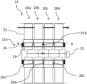
- the compressor 14 comprises a plurality of compressor stages, four of which (stages 20 a - d ) are shown in FIG. 2 .
- Each compressor stage 20 a - d comprises a compressor rotor 22 , and a corresponding electrical machine 21 a , 21 b .
- Bearings 31 are provided at either end of the compressor 14 , and optionally at intermediate stages, to allow for rotation of the rotors 22 .
- the compressor stages 20 a - d can be divided into first and second sets, with stages of the first and second sets alternating with one another.
- stages 20 a and 20 c form the first set of compressor stages
- stages 20 b and 20 d form the second set of compressor stages.
- the first and second sets are configured to rotate in opposite directions to compress air flowing through the compressor 14 , i.e. the compressor rotors are generally oppositely “handed”, i.e. are curved in opposite directions to direct air toward the right as shown in FIG. 2 , when rotated in their respective directions.
- the first set of rotors 20 a , 20 c are configured to rotate clockwise when viewed from the front of the engine (as indicated by the “+” signs on the respective rotors), while the second set of rotors 20 b , 20 d are configured to rotate counter-clockwise (as indicated by the “ ⁇ ” signs on the respective rotors).
- Each compressor rotor 22 of each stage 20 is coupled to the corresponding electrical machine 21 of that stage.
- the electric machines 21 are configured to act as motors, to drive the respective rotors 22 .
- Each electric machine comprises a stator 23 , which comprises electrical windings (not shown) and a core, as is conventional.
- the stators may be multi-phase (e.g. three phase), with multiple windings for each stator.
- Each electric machine 21 also comprises an electric machine rotor 24 , which is configured to rotate when the electric machine is in operation.
- the electric machine rotor 24 is provided radially outward of the stator 23 , in a “radial flux” configuration, with the stator 23 and rotor 24 in the same radial plane.
- the electric machine rotor 24 comprises either electromagnets, permanent magnets, or a salient, soft magnetic body, such that a rotating electric field in the stator 23 causes rotation of the machine rotor 24 .
- the electric machine rotor 24 is coupled to the corresponding compressor rotor 22 , such that the electric machine 21 causes rotation of the corresponding compressor rotor 22 . Consequently, first and second sets of electrical machines can also be defined, which form part of the first and second stages.
- the windings of each electric machine stator 23 are coupled to a motor controller 25 .
- the motor controller 25 comprises an inverter, which provides an alternating electrical current to the windings of each stator 23 .
- the windings of each stator of both the first and second sets of electrical machines, and indeed, in this embodiment, all of the electrical machines are connected to the same motor controller 25 , either in series or in parallel.
- a separate controller would be required for each electrical machine, to ensure that each controller could track the rotor position separately, to ensure that stator flux is injected at the appropriate time.
- a coupling arrangement is provided, which negates the need for separate machine controllers, thereby saving significant cost and weight.
- Adjacent stages of the compressor 14 are coupled to a coupling arrangement, such that synchronous contra-rotation is provided.
- three coupling arrangements 26 a , 26 b , 26 c are required, in order to couple stage 20 a to stage 20 b , stage 20 b to stage 20 c , and stage 20 c to stage 20 d respectively.
- FIG. 3 shows one of the coupling arrangements in more detail.
- the coupling arrangement comprises first and second toothed ring gears 27 a , 27 b , which are mounted to the electric machine rotors 24 of the respective stages 20 a , 20 b .
- a pinion gear 28 is provided, which meshes with both the toothed ring gears 27 a , 27 b .
- the pinion gear 28 is held in place by a mounting rail 29 , and is allowed to rotate in place by a bearing 30 . Consequently, clockwise movement (i.e. down in FIG. 3 ) of the machine rotor to which the toothed ring gear 27 a is attached, is translated to anti-clockwise rotation of the machine rotor to which the toothed ring gear 27 b is attached, via the pinion gear 28 .
- the stages 20 a - d are allowed to counter-rotate relative to one another, but are kept in a fixed relationship.
- the relationship may be 1:1 (i.e. the stages rotate at the same speed, but counter-rotating), or the rotors could be made to rotate with a fixed gear relationship.
- the pinion gear may have two axially spaced sets of teeth, with a first set meshing with the toothed ring gear 27 a , and a second set having a different diameter meshing with the toothed ring gear 27 b , alternatively, additional idler gears may be provided to provide the desired gear ratio.
- each of the rotors 20 a - d is known and fixed. Consequently, the controller 25 can control all of the rotors at once, whilst only tracking a single rotor of one electrical machine.
- the electric machines can be wired as shown in FIG. 4 , to provide contra-rotation of the machines, with the same controller.
- FIG. 4 shows the electrical configuration for the stator windings of two of the electrical machines 21 , for adjacent, contra-rotating stages (such as stages 20 a , 20 b ).
- three electrical phases are provided from the controller 25 .
- the phases of each of the stators (A 1 , A 2 , B 1 , B 2 , C 1 , C 2 ) are arranged in an anti-clockwise pattern, with each of the phases connected to a common neutral point.
- a first electrical phase of the controller 25 is coupled to stator A 1 of the electrical machine of the first stage 20 a , and is coupled to stator C 2 of the electrical machine of the second stage 20 a .
- a second electrical phase of the controller 25 is coupled to stator B 1 of the electrical machine of the first stage 20 a , and is coupled to stator B 2 of the electrical machine of the second stage 20 a .
- a third electrical phase of the controller 25 is coupled to stator C 1 of the electrical machine of the first stage 20 a , and is coupled to stator A 2 of the electrical machine of the second stage 20 a . Consequently, the stator windings A and C are swapped for the two electrical machines, such that they rotate in opposite directions, at the same speed.
- the electric machine stator windings are provided in series. However, as will be understood, the stator windings are the electric machines could instead be wired in parallel.
- the two contra-rotating electrical machines would ordinarily go out of phase, due to the slightly different loads experienced by the two rotors 20 a , 20 b .
- the phase relationship is maintained, and the two rotors do not go out of synch.
- the coupling arrangement does not need to carry the full torque imparted by each rotor, since only the difference in load need be accommodated, since the main torque is taken up by the individual electric motors. Consequently, the coupling arrangement 26 does not have to be capable of reacting the full torque of each rotor, and so can be relatively light weight.
- the number of rotor poles of the rotors of the electric machines 21 of the different stages could be differed, so that the machines rotate at different speeds, while staying electrically in synch.
- the gearing of the coupling arrangement 26 would also have to change accordingly.
- the gearing and relative number of poles should be an integer multiple.
- a first electric machine 21 of the first stage 20 a could be provided with sixteen rotor poles and twenty-four stator slots
- a second electric machine 21 of the second stage 20 b could be provide with eight rotor poles and twelve stator slots.
- the coupling arrangement 26 could be arrange to provide a 2:1 gearing ratio, such that the second electric machine rotates at twice the speed of the first electric machine.
- the stators could be wired as shown in FIG. 4 , to obtain counter-rotation. Consequently, different rotational speeds (and so high power density and higher efficiency) could be provided, whilst also providing for counter-rotation, while only requiring a single motor controller.
- stator of the electric machines 21 of subsequent stages 20 c , 20 d could be arranged in a similar manner, to provide counter-rotation for each stage as desired, as well as providing the required rotational speed difference.
- FIG. 5 shows an electrical arrangement for an alternative compressor 114 having six stages 120 a - f . Again, each stage has an associated rotor and electrical machine.
- a plurality of electrical machines 121 are provided, one for each stage 120 a - f .
- Each electrical machine has a corresponding number of stator slots (“S” in FIG. 5 —i.e. “5” indicates some number of slots, “2S” indicates a twice the amount of slots “5”, and so on), and a corresponding number of rotor poles (“P” in FIG. 5 —i.e. “P” indicates some number of poles, “2P” indicates twice the amount of poles “P”, and so on).
- the first electrical machine 121 a has 4S slots and 4P poles, with three electrical phases this machine has S/P/3 slots per pole per phase. This is electrically coupled to a motor controller 125 .
- the second electrical machine 121 b also has 4S slots and 4P poles, with three electrical phases this machine has S/P/3 slots per pole per phase. However, this electrical machine 121 b is electrically coupled to the controller 125 with two of the phases reversed, such that the second electrical machine 121 b rotates in the opposite direction to the first electrical machine 121 a .
- a coupling arrangement 126 a similar to that shown in FIG. 3 is provided, which provides a 1:1 gear ratio. Consequently, the second electrical machine 121 b rotates at the same speed as the first electrical machine, but in the opposite direction.
- the third electrical machine 121 c has half the number of slots and half the number of poles of machine 121 b , also with three electrical phases, resulting in the same number of slots per pole per phase and general machine characteristic.
- This electrical machine 121 c is electrically coupled to the controller 125 with the phases in the same order as the first electrical machine 121 a , such that the third electrical machine 121 c rotates in the opposite direction to the second electrical machine 121 b to which it is adjacent.
- a coupling arrangement 126 b is provided, which provides a 1:2 gear ratio.
- the third electrical machine 121 c rotates at double the mechanical speed as the first and second electric machines 121 a , 121 b , and in the same direction as the first electric machine 121 a , but in the opposite direction to the second, adjacent electric machine 121 b .
- machine 121 c has half the number of poles as machine 121 a or 121 b , but is spinning at double the mechanical speed, it runs at the same electrical frequency as machines 121 a and 121 b .
- machines 121 a , 121 b and 121 c having the same amount of slots per pole per phase and same general machine characteristic as well as being mechanically synchronised by the coupling arrangement, all three machines operate electrically in phase. Operation at the same electrical frequency and always in phase allows for control by a single controller.
- the fourth through sixth electric machines 121 d - f are arranged in a similar manner, with each being arranged to counter-rotate relative to their adjacent stage, and each with a desired relative rotational speed, as set by their pole and slot number, and the corresponding gear ratio of the corresponding coupling arrangement. Consequently, machines can have either faster or slower rotors, as is required by the compressor design, where slowing down of the consequent stage is illustrated in 121 f.
- the compressor 14 , 114 consequently provides a highly compact, energy efficient, lightweight turbomachine, suitable for a wide range of applications, such as gas turbine engines.
- an electrical power source is required to provide electrical power for the motor controller 25 , and the electrical machines 21 .
- the electrical power is provided by the turbine 16 of the gas turbine engine 10 .
- the turbine 16 is shown in greater detail in FIG. 6 .
- the turbine 16 is similar in principle to the compressor 14 , having a plurality of stages 220 a - d , each comprising a rotor 22 and an associated electric machine 21 .
- the rotors 22 are configured to convert high pressure, hot airflow into mechanical power, rather than to generate pressure, and so can be categorised as turbine blades.
- the turbine rotors 22 are configured to counter-rotate, such that each stage 220 a - d rotates in an opposite direction to an adjacent stage, and are mounted to bearings 231 .
- the electric machines 21 are configured as generators, and so are configured to convert the mechanical power from the turbine rotors 21 to electrical power.
- the generators 221 are essentially the same as the motors 21 , and could again be radial flux, permanent magnet synchronous AC machines comprising a stator 223 radially inward of a machine rotor 24 .
- Each of the stators has windings, which are wound in a similar manner to the machines 21 , with phases of adjacent machines swapped, so that contra-rotating adjacent stages produce electrical power that is synchronised with the other turbines.
- coupling arrangements 226 are provided to keep the turbines synchronised, and these may be similar to the coupling arrangement 26 .
- Each generator is coupled to a generator controller in the form of a rectifier 225 , which converts the AC waveforms generated by the generators 221 into DC current.
- the rectifier 225 is coupled to the motor control 25 through a DC power bus, such that the turbine 16 provides power to the compressor 14 .
- the gas turbine engine fan 13 is also arranged in a similar manner, with counter-rotating stages powered by electric motors.
- the fan 13 is shown in more detail in FIG. 7 .
- the electric power is provided by the turbine 16 via the electric generators 221 and rectifier 225 to a common motor controller 326 , which provide power to electric motors 321 , which drive first and second fan stages 320 a , 320 b , each of which comprises a corresponding fan rotor 322 .
- a coupling arrangement 326 is provided, which is similar to the coupling arrangement 26 .
- the disclosed arrangement could be applied to an electric aircraft propulsor, in which the propulsor is driven by electric motors which are provided with electrical power from one or a combination of a separate gas turbine engine, and an electrical storage device such as a chemical battery.
- FIG. 8 shows an electric propulsor 310 .
- the electric propulsor comprises a fan comprising first and second fan stages 313 a , 313 b .
- Each fan stage comprises a corresponding fan rotor, and a corresponding electric machine in the form of a respective motor 321 a , 321 b .
- the fan rotor and motors 321 a , 321 b are similar to those of the fan 13 , and so will not be described in further detail.
- the fan 310 differs in two important respects.
- the motors 321 a , 321 b are provided with power from a separate power stage 340 , which may for example comprise a separate combustion engine such as a gas turbine engine, an energy storage device such as a chemical battery, or any other suitable power source. In either case, the motors are provided with electrical power via a common motor controller 325 , which is similar to the motor controller 25 .
- first and second fan stages 313 a , 313 b are coupled by a coupling arrangement 326 which differs from the coupling arrangement 26 of previous embodiments.
- the coupling arrangement 326 is shown in FIG. 8 , and in further detail in FIG. 9 .
- the coupling arrangement is in the form of an epicyclic gearbox, which in the present embodiment takes the form of a single stage, star gearbox.
- the gearbox 326 comprises a sun wheel, or sun gear, 341 , which is coupled to a rotor of the second motor 312 b .
- a sun wheel, or sun gear, 341 Radially outwardly of the sun gear 341 and intermeshing therewith, in a conventional manner, is a plurality of planet gears 342 that are coupled together by a planet carrier 343 .
- the planet carrier 343 constrains the planet gears 343 to rotate about their own axis.
- the planet carrier 343 is coupled to a stationary support in the form of the fan nacelle 318 , such that the planet carrier is prevented from rotating.
- an annulus or ring gear 344 Radially outwardly of the planet gears 342 and intermeshing therewith is an annulus or ring gear 344 that is coupled via linkages to the first motor 321 a , and therefore to the first fan 313 a.
- Such an epicyclic gearbox 326 in which a sun gear is coupled to an input, a ring gear is coupled to an output, and the planet carrier is stationary, is known as a star gearbox.
- a star gearbox provides for a reduction in speed of the output relative to the input, while also providing for contra-rotation.
- the first and second fans 313 a , 313 b contra-rotate at different speeds, while being driven by the motors 312 a , 321 b .
- the majority of the torque is applied by the motors 321 a , 321 b , rather than being transmitted through the gearbox 326 , with the gearbox only acting to maintain synchronicity between the first and second motors 321 a , 321 b , such that they can be powered by the same motor controller 325 .
- two contra-rotating fans can be provided, which can each be powered by respective electric motors 321 a , 321 b .
- Contra-rotation allows for an outlet guide vane between the fans 313 a , 313 b to be omitted, thereby decreasing weight.
- the synchronicity between the first and second motors 321 a , 321 b ensured by the gearbox 326 allows for only a single motor controller to be used, thereby greatly decreasing weight further.
- the gearbox 326 may be rated to accommodate the full torque/power rating required to transmit power to the first fan 313 a from the second motor 321 b , and/or to the second fan 313 b from the first motor 321 a , albeit for a short period. Consequently, in the event of a failure of one of the motors 321 a , 321 b , both fans can continue to be powered, either at full power for a short duration, or at a reduced power for a longer duration, by transmitting torque from one motor 321 , 321 b to both fans 313 a , 313 b via the gearbox 326 . Consequently, thrust can continue to be produced efficiently, thereby reducing the consequences of a motor failure. On the other hand, in the event of a gearbox failure, both fans can continue to operate, though with reduced efficiency, as synchronicity is no longer maintained.
- FIG. 10 shows an alternative gearbox 426 , which may be used in place of the gearbox 26 or 326 .
- the gearbox 426 comprises two rings 441 , 444 of permanent magnets 450 a , 450 b , 451 a , 451 b , with a ring of steel pole pieces 452 in between.
- the orientation of the permanent magnets 450 a , 450 b alternate about the circumference of the ring 441 , with the magnet 450 a having the opposite North-South orientation to the magnet 450 b .
- the orientation of the permanent magnets 451 a , 451 b alternate about the circumference of the ring 444 , with the magnet 451 a having the opposite north-south orientation to the magnet 451 b
- the steel pole 452 pieces act as flux paths from each of the rings of magnets 441 , 444 . This has the effect of creating harmonics in the fields produced by each ring of magnets. By careful selection of pole numbers, one can couple to the harmonic field and this creates a gear ratio. The behaviour of this gear is similar to the star gearbox 326 . Consequently, the inner ring 441 acts in a similar manner to the sun gear 341 , and so is coupled to the rotor of the second motor 312 b . The steel pole pieces 452 take the place of the planet carrier 343 , and so these are held still. The outer ring of magnets 44 takes the place of the ring gear 344 , and so is coupled to the rotor of the first motor 312 a . The ratios of magnets 450 a , 450 b , 451 a , 451 b and pole pieces 452 defines the gear ratio to define a magnetic gearbox.
- Magnetic gearboxes can have high efficiency, and long lives, due to the lack of contacting gear teeth.
- One drawback of magnetic gearboxes however is the relatively low torque capacity of such devices.
- the torque transmitted through the gearbox 426 is relatively low, and so a magnetic gearbox may be suitable.
- one or more shafts may be provided, in addition to the motors or generators, to couple compressors and turbines.
- the electric compressors could be provided independently of the electric turbines.
- Other types of electric motors could be used.
- the invention could be applied to other types of turbomachinery, such as pumps and propellers.
- a still further alternative would be the use of a coupling arrangement in the form of a magnetic gearbox, in place of the mechanical gearboxes described herein.
- a magnetic gearbox may be lighter weight, and less subject to wear in failure, in view of the lack of contacting parts.
Landscapes
- Engineering & Computer Science (AREA)
- Mechanical Engineering (AREA)
- General Engineering & Computer Science (AREA)
- Chemical & Material Sciences (AREA)
- Combustion & Propulsion (AREA)
- Power Engineering (AREA)
- Connection Of Motors, Electrical Generators, Mechanical Devices, And The Like (AREA)
Abstract
Description
Claims (9)
Applications Claiming Priority (3)
| Application Number | Priority Date | Filing Date | Title |
|---|---|---|---|
| GBGB1902095.7A GB201902095D0 (en) | 2019-02-15 | 2019-02-15 | Electric turbomachine |
| GB1902095.7 | 2019-02-15 | ||
| GB1902095 | 2019-02-15 |
Publications (2)
| Publication Number | Publication Date |
|---|---|
| US20200263545A1 US20200263545A1 (en) | 2020-08-20 |
| US11680486B2 true US11680486B2 (en) | 2023-06-20 |
Family
ID=65998592
Family Applications (1)
| Application Number | Title | Priority Date | Filing Date |
|---|---|---|---|
| US16/779,712 Active 2040-06-14 US11680486B2 (en) | 2019-02-15 | 2020-02-03 | Electric turbomachine |
Country Status (3)
| Country | Link |
|---|---|
| US (1) | US11680486B2 (en) |
| EP (1) | EP3696388B1 (en) |
| GB (1) | GB201902095D0 (en) |
Cited By (1)
| Publication number | Priority date | Publication date | Assignee | Title |
|---|---|---|---|---|
| US12546327B1 (en) * | 2024-08-08 | 2026-02-10 | Hamilton Sundstrand Corporation | Air cycle machine with axial rotors and integrated cabin air compressor |
Families Citing this family (2)
| Publication number | Priority date | Publication date | Assignee | Title |
|---|---|---|---|---|
| US11613371B1 (en) * | 2021-11-19 | 2023-03-28 | John Daniel Romo | Electric vacuum jet engine |
| GB202215124D0 (en) * | 2022-10-13 | 2022-11-30 | Astron Systems Ltd | Rocket engine |
Citations (16)
| Publication number | Priority date | Publication date | Assignee | Title |
|---|---|---|---|---|
| US2413225A (en) | 1941-05-14 | 1946-12-24 | Rolls Royce | Internal-combustion turbine |
| US3705775A (en) | 1970-01-15 | 1972-12-12 | Snecma | Gas turbine power plants |
| US7199484B2 (en) * | 2005-07-05 | 2007-04-03 | Gencor Industries Inc. | Water current generator |
| US20090289516A1 (en) * | 2008-05-22 | 2009-11-26 | Rolls-Royce Plc | Electrical generator arrangement |
| US20100326050A1 (en) * | 2009-06-30 | 2010-12-30 | Jan Christopher Schilling | Aircraft gas turbine engine counter-rotatable generator |
| US20110024567A1 (en) | 2009-07-28 | 2011-02-03 | Rolls-Royce North American Technologies, Inc. | Electrical power generation apparatus for contra-rotating open-rotor aircraft propulsion system |
| US20120326539A1 (en) * | 2011-06-23 | 2012-12-27 | Rolls-Royce Plc | Electrical machine with contra-rotating rotors |
| US8464511B1 (en) * | 2012-01-06 | 2013-06-18 | Hamilton Sundstrand Corporation | Magnetically coupled contra-rotating propulsion stages |
| US20140212299A1 (en) | 2011-12-16 | 2014-07-31 | Rolls-Royce Plc | Propulsion engine |
| US20160160867A1 (en) | 2013-03-15 | 2016-06-09 | Embry-Riddle Aeronautical University, Inc. | Electrically coupled counter-rotation for gas turbine compressors |
| US20170159665A1 (en) | 2014-02-03 | 2017-06-08 | Nuovo Pignone Sri | Multistage turbomachine with embedded electric motors |
| US9866094B2 (en) * | 2015-10-27 | 2018-01-09 | Kuo-Chang Huang | Fluid driven electric generator |
| US20200023982A1 (en) * | 2018-07-19 | 2020-01-23 | United Technologies Corporation | Aircraft hybrid propulsion fan drive gear system dc motors and generators |
| US10700580B2 (en) * | 2017-03-17 | 2020-06-30 | Rolls -Royce Plc | Electrical machine |
| US10794617B2 (en) * | 2017-11-02 | 2020-10-06 | Rolls-Royce Plc | Thermal management system |
| US20200340406A1 (en) * | 2018-06-22 | 2020-10-29 | Safran Aero Boosters Sa | Hybrid Transmission Turbojet Engine |
-
2019
- 2019-02-15 GB GBGB1902095.7A patent/GB201902095D0/en not_active Ceased
-
2020
- 2020-01-20 EP EP20152654.8A patent/EP3696388B1/en active Active
- 2020-02-03 US US16/779,712 patent/US11680486B2/en active Active
Patent Citations (17)
| Publication number | Priority date | Publication date | Assignee | Title |
|---|---|---|---|---|
| US2413225A (en) | 1941-05-14 | 1946-12-24 | Rolls Royce | Internal-combustion turbine |
| US3705775A (en) | 1970-01-15 | 1972-12-12 | Snecma | Gas turbine power plants |
| US7199484B2 (en) * | 2005-07-05 | 2007-04-03 | Gencor Industries Inc. | Water current generator |
| US20090289516A1 (en) * | 2008-05-22 | 2009-11-26 | Rolls-Royce Plc | Electrical generator arrangement |
| US20100326050A1 (en) * | 2009-06-30 | 2010-12-30 | Jan Christopher Schilling | Aircraft gas turbine engine counter-rotatable generator |
| US20110024567A1 (en) | 2009-07-28 | 2011-02-03 | Rolls-Royce North American Technologies, Inc. | Electrical power generation apparatus for contra-rotating open-rotor aircraft propulsion system |
| US20120326539A1 (en) * | 2011-06-23 | 2012-12-27 | Rolls-Royce Plc | Electrical machine with contra-rotating rotors |
| US20140212299A1 (en) | 2011-12-16 | 2014-07-31 | Rolls-Royce Plc | Propulsion engine |
| US20130174533A1 (en) * | 2012-01-06 | 2013-07-11 | Hamilton Sundstrand Corporation | Magnetically coupled contra-rotating propulsion stages |
| US8464511B1 (en) * | 2012-01-06 | 2013-06-18 | Hamilton Sundstrand Corporation | Magnetically coupled contra-rotating propulsion stages |
| US20160160867A1 (en) | 2013-03-15 | 2016-06-09 | Embry-Riddle Aeronautical University, Inc. | Electrically coupled counter-rotation for gas turbine compressors |
| US20170159665A1 (en) | 2014-02-03 | 2017-06-08 | Nuovo Pignone Sri | Multistage turbomachine with embedded electric motors |
| US9866094B2 (en) * | 2015-10-27 | 2018-01-09 | Kuo-Chang Huang | Fluid driven electric generator |
| US10700580B2 (en) * | 2017-03-17 | 2020-06-30 | Rolls -Royce Plc | Electrical machine |
| US10794617B2 (en) * | 2017-11-02 | 2020-10-06 | Rolls-Royce Plc | Thermal management system |
| US20200340406A1 (en) * | 2018-06-22 | 2020-10-29 | Safran Aero Boosters Sa | Hybrid Transmission Turbojet Engine |
| US20200023982A1 (en) * | 2018-07-19 | 2020-01-23 | United Technologies Corporation | Aircraft hybrid propulsion fan drive gear system dc motors and generators |
Non-Patent Citations (3)
| Title |
|---|
| European search report dated Jul. 8, 2020, issued in EP Patent Application No. 20152654.8. |
| Great Britain search report dated Aug. 13, 2019, issued in GB Patent Application No. 1902095.7. |
| Response to Extended European Search Report from counterpart EP Application No. 20152654.8 dated Jul. 17, 2020, filed Jan. 6, 2021, 39 pgs. |
Cited By (2)
| Publication number | Priority date | Publication date | Assignee | Title |
|---|---|---|---|---|
| US12546327B1 (en) * | 2024-08-08 | 2026-02-10 | Hamilton Sundstrand Corporation | Air cycle machine with axial rotors and integrated cabin air compressor |
| US20260043410A1 (en) * | 2024-08-08 | 2026-02-12 | Hamilton Sundstrand Corporation | Air cycle machine with axial rotors and integrated cabin air compressor |
Also Published As
| Publication number | Publication date |
|---|---|
| EP3696388A1 (en) | 2020-08-19 |
| EP3696388B1 (en) | 2022-10-12 |
| GB201902095D0 (en) | 2019-04-03 |
| US20200263545A1 (en) | 2020-08-20 |
Similar Documents
| Publication | Publication Date | Title |
|---|---|---|
| US20200227966A1 (en) | Turbomachine | |
| US11230942B2 (en) | Gas turbine engine electrical generator | |
| US8198744B2 (en) | Integrated boost cavity ring generator for turbofan and turboshaft engines | |
| US11364991B2 (en) | Aircraft propulsion system | |
| US8063527B2 (en) | Gas turbine engine assembly including dual sided/dual shaft electrical machine | |
| CA2707943C (en) | Aircraft gas turbine engine counter-rotatable generator | |
| US8063528B2 (en) | Counter-rotatable generator | |
| US12352214B2 (en) | Differential gearbox assembly for a turbine engine | |
| EP1936150A2 (en) | High-speed high-pole count generators | |
| US10513986B2 (en) | Counter-rotating electric generator in turbine engine | |
| US11680486B2 (en) | Electric turbomachine | |
| US20220235726A1 (en) | Electric machine, drive system, and use thereof | |
| EP3511557B1 (en) | An epicyclic geartrain | |
| EP4068589A1 (en) | Turbine generator |
Legal Events
| Date | Code | Title | Description |
|---|---|---|---|
| FEPP | Fee payment procedure |
Free format text: ENTITY STATUS SET TO UNDISCOUNTED (ORIGINAL EVENT CODE: BIG.); ENTITY STATUS OF PATENT OWNER: LARGE ENTITY |
|
| AS | Assignment |
Owner name: ROLLS-ROYCE PLC, GREAT BRITAIN Free format text: ASSIGNMENT OF ASSIGNORS INTEREST;ASSIGNORS:PALMER, CHLOE J.;SHIROKOV, VLADIMIR;SIGNING DATES FROM 20190215 TO 20190218;REEL/FRAME:055256/0349 |
|
| STPP | Information on status: patent application and granting procedure in general |
Free format text: DOCKETED NEW CASE - READY FOR EXAMINATION |
|
| STPP | Information on status: patent application and granting procedure in general |
Free format text: NON FINAL ACTION MAILED |
|
| STPP | Information on status: patent application and granting procedure in general |
Free format text: RESPONSE TO NON-FINAL OFFICE ACTION ENTERED AND FORWARDED TO EXAMINER |
|
| STPP | Information on status: patent application and granting procedure in general |
Free format text: FINAL REJECTION MAILED |
|
| STPP | Information on status: patent application and granting procedure in general |
Free format text: RESPONSE AFTER FINAL ACTION FORWARDED TO EXAMINER |
|
| STPP | Information on status: patent application and granting procedure in general |
Free format text: ADVISORY ACTION MAILED |
|
| STPP | Information on status: patent application and granting procedure in general |
Free format text: DOCKETED NEW CASE - READY FOR EXAMINATION |
|
| STPP | Information on status: patent application and granting procedure in general |
Free format text: NON FINAL ACTION MAILED |
|
| STPP | Information on status: patent application and granting procedure in general |
Free format text: RESPONSE TO NON-FINAL OFFICE ACTION ENTERED AND FORWARDED TO EXAMINER |
|
| STPP | Information on status: patent application and granting procedure in general |
Free format text: FINAL REJECTION MAILED |
|
| STCF | Information on status: patent grant |
Free format text: PATENTED CASE |