US11673543B2 - Vehicle control system and vehicle control method - Google Patents
Vehicle control system and vehicle control method Download PDFInfo
- Publication number
- US11673543B2 US11673543B2 US16/654,146 US201916654146A US11673543B2 US 11673543 B2 US11673543 B2 US 11673543B2 US 201916654146 A US201916654146 A US 201916654146A US 11673543 B2 US11673543 B2 US 11673543B2
- Authority
- US
- United States
- Prior art keywords
- vehicle
- infrastructure
- alighting
- coordinates
- image data
- Prior art date
- Legal status (The legal status is an assumption and is not a legal conclusion. Google has not performed a legal analysis and makes no representation as to the accuracy of the status listed.)
- Active, expires
Links
Images


Classifications
-
- G—PHYSICS
- G05—CONTROLLING; REGULATING
- G05D—SYSTEMS FOR CONTROLLING OR REGULATING NON-ELECTRIC VARIABLES
- G05D1/00—Control of position, course, altitude or attitude of land, water, air or space vehicles, e.g. using automatic pilots
- G05D1/02—Control of position or course in two dimensions
- G05D1/021—Control of position or course in two dimensions specially adapted to land vehicles
- G05D1/0212—Control of position or course in two dimensions specially adapted to land vehicles with means for defining a desired trajectory
-
- B—PERFORMING OPERATIONS; TRANSPORTING
- B60—VEHICLES IN GENERAL
- B60W—CONJOINT CONTROL OF VEHICLE SUB-UNITS OF DIFFERENT TYPE OR DIFFERENT FUNCTION; CONTROL SYSTEMS SPECIALLY ADAPTED FOR HYBRID VEHICLES; ROAD VEHICLE DRIVE CONTROL SYSTEMS FOR PURPOSES NOT RELATED TO THE CONTROL OF A PARTICULAR SUB-UNIT
- B60W30/00—Purposes of road vehicle drive control systems not related to the control of a particular sub-unit, e.g. of systems using conjoint control of vehicle sub-units
- B60W30/02—Control of vehicle driving stability
- B60W30/045—Improving turning performance
-
- B—PERFORMING OPERATIONS; TRANSPORTING
- B60—VEHICLES IN GENERAL
- B60W—CONJOINT CONTROL OF VEHICLE SUB-UNITS OF DIFFERENT TYPE OR DIFFERENT FUNCTION; CONTROL SYSTEMS SPECIALLY ADAPTED FOR HYBRID VEHICLES; ROAD VEHICLE DRIVE CONTROL SYSTEMS FOR PURPOSES NOT RELATED TO THE CONTROL OF A PARTICULAR SUB-UNIT
- B60W30/00—Purposes of road vehicle drive control systems not related to the control of a particular sub-unit, e.g. of systems using conjoint control of vehicle sub-units
- B60W30/06—Automatic manoeuvring for parking
-
- B—PERFORMING OPERATIONS; TRANSPORTING
- B60—VEHICLES IN GENERAL
- B60W—CONJOINT CONTROL OF VEHICLE SUB-UNITS OF DIFFERENT TYPE OR DIFFERENT FUNCTION; CONTROL SYSTEMS SPECIALLY ADAPTED FOR HYBRID VEHICLES; ROAD VEHICLE DRIVE CONTROL SYSTEMS FOR PURPOSES NOT RELATED TO THE CONTROL OF A PARTICULAR SUB-UNIT
- B60W30/00—Purposes of road vehicle drive control systems not related to the control of a particular sub-unit, e.g. of systems using conjoint control of vehicle sub-units
- B60W30/08—Active safety systems predicting or avoiding probable or impending collision or attempting to minimise its consequences
- B60W30/095—Predicting travel path or likelihood of collision
-
- B—PERFORMING OPERATIONS; TRANSPORTING
- B60—VEHICLES IN GENERAL
- B60W—CONJOINT CONTROL OF VEHICLE SUB-UNITS OF DIFFERENT TYPE OR DIFFERENT FUNCTION; CONTROL SYSTEMS SPECIALLY ADAPTED FOR HYBRID VEHICLES; ROAD VEHICLE DRIVE CONTROL SYSTEMS FOR PURPOSES NOT RELATED TO THE CONTROL OF A PARTICULAR SUB-UNIT
- B60W30/00—Purposes of road vehicle drive control systems not related to the control of a particular sub-unit, e.g. of systems using conjoint control of vehicle sub-units
- B60W30/18—Propelling the vehicle
- B60W30/18009—Propelling the vehicle related to particular drive situations
- B60W30/181—Preparing for stopping
-
- B—PERFORMING OPERATIONS; TRANSPORTING
- B60—VEHICLES IN GENERAL
- B60W—CONJOINT CONTROL OF VEHICLE SUB-UNITS OF DIFFERENT TYPE OR DIFFERENT FUNCTION; CONTROL SYSTEMS SPECIALLY ADAPTED FOR HYBRID VEHICLES; ROAD VEHICLE DRIVE CONTROL SYSTEMS FOR PURPOSES NOT RELATED TO THE CONTROL OF A PARTICULAR SUB-UNIT
- B60W40/00—Estimation or calculation of non-directly measurable driving parameters for road vehicle drive control systems not related to the control of a particular sub unit, e.g. by using mathematical models
- B60W40/02—Estimation or calculation of non-directly measurable driving parameters for road vehicle drive control systems not related to the control of a particular sub unit, e.g. by using mathematical models related to ambient conditions
-
- B—PERFORMING OPERATIONS; TRANSPORTING
- B60—VEHICLES IN GENERAL
- B60W—CONJOINT CONTROL OF VEHICLE SUB-UNITS OF DIFFERENT TYPE OR DIFFERENT FUNCTION; CONTROL SYSTEMS SPECIALLY ADAPTED FOR HYBRID VEHICLES; ROAD VEHICLE DRIVE CONTROL SYSTEMS FOR PURPOSES NOT RELATED TO THE CONTROL OF A PARTICULAR SUB-UNIT
- B60W40/00—Estimation or calculation of non-directly measurable driving parameters for road vehicle drive control systems not related to the control of a particular sub unit, e.g. by using mathematical models
- B60W40/10—Estimation or calculation of non-directly measurable driving parameters for road vehicle drive control systems not related to the control of a particular sub unit, e.g. by using mathematical models related to vehicle motion
-
- B—PERFORMING OPERATIONS; TRANSPORTING
- B60—VEHICLES IN GENERAL
- B60W—CONJOINT CONTROL OF VEHICLE SUB-UNITS OF DIFFERENT TYPE OR DIFFERENT FUNCTION; CONTROL SYSTEMS SPECIALLY ADAPTED FOR HYBRID VEHICLES; ROAD VEHICLE DRIVE CONTROL SYSTEMS FOR PURPOSES NOT RELATED TO THE CONTROL OF A PARTICULAR SUB-UNIT
- B60W60/00—Drive control systems specially adapted for autonomous road vehicles
- B60W60/001—Planning or execution of driving tasks
-
- G—PHYSICS
- G05—CONTROLLING; REGULATING
- G05D—SYSTEMS FOR CONTROLLING OR REGULATING NON-ELECTRIC VARIABLES
- G05D1/00—Control of position, course, altitude or attitude of land, water, air or space vehicles, e.g. using automatic pilots
- G05D1/0011—Control of position, course, altitude or attitude of land, water, air or space vehicles, e.g. using automatic pilots associated with a remote control arrangement
- G05D1/0016—Control of position, course, altitude or attitude of land, water, air or space vehicles, e.g. using automatic pilots associated with a remote control arrangement characterised by the operator's input device
-
- G—PHYSICS
- G05—CONTROLLING; REGULATING
- G05D—SYSTEMS FOR CONTROLLING OR REGULATING NON-ELECTRIC VARIABLES
- G05D1/00—Control of position, course, altitude or attitude of land, water, air or space vehicles, e.g. using automatic pilots
- G05D1/0088—Control of position, course, altitude or attitude of land, water, air or space vehicles, e.g. using automatic pilots characterized by the autonomous decision making process, e.g. artificial intelligence, predefined behaviours
-
- G—PHYSICS
- G05—CONTROLLING; REGULATING
- G05D—SYSTEMS FOR CONTROLLING OR REGULATING NON-ELECTRIC VARIABLES
- G05D1/00—Control of position, course, altitude or attitude of land, water, air or space vehicles, e.g. using automatic pilots
- G05D1/02—Control of position or course in two dimensions
- G05D1/021—Control of position or course in two dimensions specially adapted to land vehicles
- G05D1/0231—Control of position or course in two dimensions specially adapted to land vehicles using optical position detecting means
- G05D1/0246—Control of position or course in two dimensions specially adapted to land vehicles using optical position detecting means using a video camera in combination with image processing means
-
- G—PHYSICS
- G08—SIGNALLING
- G08G—TRAFFIC CONTROL SYSTEMS
- G08G1/00—Traffic control systems for road vehicles
- G08G1/16—Anti-collision systems
- G08G1/168—Driving aids for parking, e.g. acoustic or visual feedback on parking space
-
- B—PERFORMING OPERATIONS; TRANSPORTING
- B60—VEHICLES IN GENERAL
- B60W—CONJOINT CONTROL OF VEHICLE SUB-UNITS OF DIFFERENT TYPE OR DIFFERENT FUNCTION; CONTROL SYSTEMS SPECIALLY ADAPTED FOR HYBRID VEHICLES; ROAD VEHICLE DRIVE CONTROL SYSTEMS FOR PURPOSES NOT RELATED TO THE CONTROL OF A PARTICULAR SUB-UNIT
- B60W2420/00—Indexing codes relating to the type of sensors based on the principle of their operation
- B60W2420/40—Photo, light or radio wave sensitive means, e.g. infrared sensors
- B60W2420/403—Image sensing, e.g. optical camera
-
- B60W2420/42—
-
- B—PERFORMING OPERATIONS; TRANSPORTING
- B60—VEHICLES IN GENERAL
- B60W—CONJOINT CONTROL OF VEHICLE SUB-UNITS OF DIFFERENT TYPE OR DIFFERENT FUNCTION; CONTROL SYSTEMS SPECIALLY ADAPTED FOR HYBRID VEHICLES; ROAD VEHICLE DRIVE CONTROL SYSTEMS FOR PURPOSES NOT RELATED TO THE CONTROL OF A PARTICULAR SUB-UNIT
- B60W2420/00—Indexing codes relating to the type of sensors based on the principle of their operation
- B60W2420/50—Magnetic or electromagnetic sensors
- B60W2420/506—Inductive sensors, i.e. passive wheel sensors
-
- B—PERFORMING OPERATIONS; TRANSPORTING
- B60—VEHICLES IN GENERAL
- B60W—CONJOINT CONTROL OF VEHICLE SUB-UNITS OF DIFFERENT TYPE OR DIFFERENT FUNCTION; CONTROL SYSTEMS SPECIALLY ADAPTED FOR HYBRID VEHICLES; ROAD VEHICLE DRIVE CONTROL SYSTEMS FOR PURPOSES NOT RELATED TO THE CONTROL OF A PARTICULAR SUB-UNIT
- B60W2556/00—Input parameters relating to data
- B60W2556/45—External transmission of data to or from the vehicle
-
- G05D2201/0213—
Definitions
- the present disclosure relates to a vehicle control system and a vehicle control method.
- ADAS Advanced Driver Assist System
- SPAS smart parking assist system
- a vehicle control system includes: one or more image sensors disposed on a vehicle to have a field of view of an outside of the vehicle and configured to capture image data; a processor configured to process the image data captured by the image sensor; and a controller configured to set a travelling route from an alighting infrastructure to a parking infrastructure based at least in part on processing of the image data, and control the vehicle stopped in the alighting infrastructure to travel along the travelling route and to be parked in the parking infrastructure, wherein the controller is configured to: determine position coordinates and a type of stop of the vehicle in the alighting infrastructure based on a result of the processing of the image data and previously stored alighting infrastructure information; extract position coordinates of the parking infrastructure based on previously stored parking infrastructure information; set the travelling route using the position coordinates of the vehicle and the position coordinates of the parking infrastructure; and determine an initial behavior for a start of the stopped vehicle based on the type of stop of the vehicle.
- a vehicle control system includes: one or more image sensors disposed on a vehicle to have a field of view of an outside of the vehicle and configured to capture image data; a smart parking assist system (SPAS) module configured to search a parking space existing around the vehicle and controlling a behavior of the vehicle such that the vehicle is parked in the parking space or the vehicle parked in the parking space is unparked; and a domain control unit (DCU) configured to process the image data captured by the image sensor and control at least one driver assistance system provided in the vehicle and including the SPAS module, wherein the DCU is configured to: determine position coordinates and a type of stop of the vehicle in an alighting infrastructure based on a result of processing of the image data and previously stored alighting infrastructure information; extract position coordinates of a parking infrastructure based on previously stored parking infrastructure information; set a travelling route using the position coordinates of the vehicle and the position coordinates of the parking infrastructure; and determine an initial behavior for a start of the stopped vehicle based on the type of stop
- an image sensor disposed on a vehicle to have a field of view of an outside of the vehicle and configured to capture image data is characterized in that: the image data is processed by a processor and is used to determine position coordinates and a type of stop of the vehicle in an alighting infrastructure; and the position coordinates of the vehicle is used to set a travelling route together with position coordinates of a parking infrastructure that are extracted from previously stored parking infrastructure information.
- a vehicle control method includes: capturing image data using one or more image sensor disposed on a vehicle to have a field of view of an outside of the vehicle; processing the image data captured by the image sensor; and setting a travelling route from an alighting infrastructure to a parking infrastructure based at least in part on processing of the image data, and controlling the vehicle stopped in the alighting infrastructure to travel along the travelling route and to be parked in the parking infrastructure, wherein the controlling of the vehicle to be parked in the parking infrastructure includes: determining position coordinates and a type of stop of the vehicle in the alighting infrastructure based on a result of processing of the image data and previously stored alighting infrastructure information; extracting position coordinates of the parking infrastructure based on previously stored parking infrastructure; setting the travelling route using the position coordinates of the vehicle and the position coordinates of the parking infrastructure; and determining an initial behavior for a start of the stopped vehicle based on the type of stop of the vehicle.
- FIG. 1 is a view illustrating a vehicle control system according to the present disclosure
- FIG. 2 is a view illustrating a vehicle and an infrastructure according to the present disclosure
- FIG. 3 is a view for describing an embodiment of determining the position coordinates of a vehicle positioned in an alighting infrastructure according to the present disclosure
- FIG. 4 is a view for describing another embodiment of determining the position coordinates of a vehicle positioned in an alighting infrastructure according to the present disclosure
- FIG. 5 is a view for describing an embodiment of determining a type of stop of a vehicle stopped in an alighting infrastructure according to the present disclosure
- FIG. 6 is a view for describing another embodiment of determining a type of stop of a vehicle stopped in an alighting infrastructure according to the present disclosure
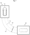
- FIG. 7 is a view for describing an embodiment of setting a travelling route from an alighting infrastructure to a parking infrastructure according to the present disclosure
- FIG. 8 is a view for describing an embodiment of setting an exit route from a parking infrastructure to an exit infrastructure according to the present disclosure.
- FIG. 9 is a flowchart showing a vehicle control method according to the present disclosure.
- FIG. 1 is a view illustrating a vehicle control system 100 according to the present disclosure.
- a vehicle may execute the vehicle control system 100 .
- the vehicle control system 100 may include an image sensor 110 , a non-image sensor 120 , a processor 130 , a controller 140 , and the like.
- the image sensor 110 may be disposed on the vehicle to have a field of view of the outside of the vehicle, and configured to capture image data.
- the image sensor 110 may be provided in one or more units thereof, and mounted on each part of the vehicle to have a field of view of the front side, lateral side, or rear side of the vehicle.
- image information photographed by the image sensor 110 is composed of image data
- the image information may refer to image data captured by the image sensor 110 .
- image information photographed by the image sensor 110 refers to image data captured by the image sensor 110 .
- the image data captured by the image sensor 110 may be generated, for example, in any form of raw AVI, MPEG-4, H.264, DivX, and JPEG.
- the image data captured by the image sensor 110 may be processed by the processor 130 .
- the non-image sensor 120 may be disposed on the vehicle to have a field of sensing of the outside of the vehicle and configured to capture sensing data.
- the non-image sensor 120 may be provided in at least one unit thereof, and examples of the non-image sensor 120 may include a radar, a lidar, an ultrasonic sensor, and the like.
- the sensing data captured by the non-image sensor 120 may be processed by the processor 130 .
- the processor 130 may be configured to process at least one of image data captured by the image sensor 110 and sensing data captured by the non-image 120 , and may be provided in at least one unit thereof.
- the processor 130 may be configured to process image data captured by the image sensor 110 and sensing data captured by the non-image sensor 120 , and may be provided in a plurality of units thereof to process image data and sensing data.
- the controller 140 may set a travelling route from an alighting infrastructure (Infra) to a parking infrastructure (Infra) based at least in part on the processing of the image data, and control the vehicle stopped in the alighting infrastructure to travel along the travelling route and to be parked in the parking infrastructure.
- alighting infrastructure Infra
- a parking infrastructure Infra
- the controller 140 may determine position coordinates and a type of stop of the vehicle in the alighting infrastructure on the basis of a result of processing of the image data and previously stored alighting infrastructure information, extract position coordinates of the parking infrastructure on the basis of previously stored parking infrastructure information, set a travelling route using the position coordinates of the vehicle and the position coordinates of the parking infrastructure, and determine an initial behavior for a start of the stopped vehicle on the basis of the type of stop of the vehicle.
- the alighting infrastructure may refer to a structure having a certain alighting zone such that the vehicle enters the alighting infrastructure and makes a stop.
- the driver in the vehicle may alight the vehicle.
- grid lines may be marked.
- the position coordinates of the vehicle may be more accurately determined by the grid lines.
- the alighting infrastructure information refers to information about the alighting infrastructure.
- the alighting infrastructure information may include a plurality of grid lines, a size and form of the alighting infrastructure, position coordinates of the alighting infrastructure, and the like.
- the parking infrastructure may refer to a structure having a certain parking zone.
- the parking zone of the parking infrastructure may be marked with grid lines.
- the position coordinates of the vehicle may be determined more accurately by the grid lines.
- the parking infrastructure information refers to information about the parking infrastructure, and specifically, the parking infrastructure information may include a plurality of grid lines, a size and form of the parking infrastructure, position coordinates of the parking infrastructure, and the like.
- the alighting infrastructure information and the parking infrastructure information may be stored in advance, by a driver in a vehicle, or by design and experimental values. When the alighting infrastructure information and the parking infrastructure information are stored by the driver, the information may be updated each time.
- the storing of the alighting infrastructure information and the parking infrastructure information is not limited thereto.
- the controller 140 may further include a memory for storing the above-described alighting infrastructure information, parking infrastructure information, and the like.
- the type of stop of a vehicle may refer to the form of a vehicle stopped in the alighting infrastructure.
- the type of stop is, for example, a longitudinal stop in which the vehicle is stopped in the longitudinal direction, a traverse stop in which the vehicle is stopped in the traverse direction, an oblique stop in which the vehicle is stopped at a predetermined angle with respect to the alighting infrastructure, and the like.
- the type of stop of the vehicle is not limited thereto.
- the longitudinal stop and the traverse stop may be a relative concept determined according to a specific criterion.
- the initial behavior may refer to a movement when the vehicle positioned in the alighting infrastructure first starts travelling.
- the initial behavior represents the steering angle of the vehicle, the degree of acceleration, the head lamp, the back-up lamp, the turn signal lamp, and the like, but the present disclosure is not limited thereto.
- the initial behavior when the vehicle 210 first starts travelling, in particular, the steering angle may be determined according to the type of stop of the vehicle 210 stopped in the alighting infrastructure 220 .
- the controller 140 may determine the above-described position coordinates and type of stop of the vehicle based in part on the processing of the sensing data instead of the image data, set a travelling route according to the position coordinates and type of stop of the vehicle, and control the vehicle to travel along the travelling route and to be parked in the parking infrastructure In addition, the controller 140 may determine the position coordinates and the type of stop of the vehicle in the same manner as described above based on the processing result of each of the image data and the sensing data.
- the controller 140 may be implemented using an electronic controller unit (ECU), a micro controller unit (MCU), or the like.
- ECU electronic controller unit
- MCU micro controller unit
- the controller 140 may be implemented using a domain control unit (DCU) configured to perform the function of the processor 130 , the above described operation of the controller 140 , and the function of performing output to a steering control module, a brake control mode, an adaptive driving assistance system (ADAS) module, and the like to control the vehicle.
- DCU domain control unit
- ADAS adaptive driving assistance system
- the ADAS module may refer to various driver assistance systems implemented in a module, and the driver assistance systems may include a smart parking assistance system (SPAS), a blind spot detection (BSD) system, an adaptive cruise control (ACC) system, a lane departure warning system (LDWS), a lane keeping assist system (LKAS), a lane change assist system (LCAS), and the like, but the implementation of the ADAS module is not limited thereto.
- a smart parking assistance system SSD
- ACC adaptive cruise control
- LDWS lane departure warning system
- LKAS lane keeping assist system
- LCAS lane change assist system
- An embodiment of the vehicle control system 100 that operates using the DCU capable of performing all the functions of the processor 130 and the controller 140 described above may include one or more image sensors 110 disposed on the vehicle to have a field of view of the outside of the vehicle and configured to capture image data, a SPAS module configured to search a parking space existing around the vehicle and control the behavior of the vehicle such that the vehicle is parked in the parking space or the vehicle parked in the parking space is unparked, and a DCU configured to process the image data captured by the image sensor 110 and control at least one driver assistance system provided in the vehicle including the SPAS.
- the DCU determines the position coordinates and the type of stop of the vehicle in the alighting infrastructure based on the processing result of the image data and the previously stored alighting infrastructure information, extracts the position coordinates of the parking infrastructure based on the previously stored parking infrastructure information, sets the travelling route using the position coordinates of the vehicle and the position coordinates of the parking infrastructure, and determines the initial behavior when the stopped vehicle starts based on the type of stop of the vehicle in the same manner of the controller 140 described above.
- FIG. 2 is a view illustrating a vehicle 210 and infrastructures 220 , 230 , and 240 according to the present disclosure.
- a driver in the vehicle 210 according to the present disclosure may drive the vehicle 210 to enter the alighting infrastructure 220 .
- the driver in the vehicle 210 may alight the vehicle 210 and transmit a travelling command signal using a wireless communication terminal.
- the wireless communication terminal refers to all types of devices capable of performing wireless communication, such as a smart phone, a smart key, and the like.
- the travelling command signal refers to a signal that instructs the vehicle 210 positioned in the alighting infrastructure 220 to travel and be parked in the parking infrastructure 230 .
- a communication device for example, a set-top box, capable of communicating with the vehicle 210 may be disposed in the vicinity of the alighting infrastructure 220
- a communication device for example, a beacon, capable of communicating with the vehicle 210 may be disposed in the vicinity of the parking infrastructure 230 .
- the vehicle 210 When the vehicle 210 receives the travelling command signal, the vehicle 210 autonomously travels along the travelling route set from the alighting infrastructure 220 to the parking infrastructure 230 and is parked in the parking infrastructure 230 .
- the controller 140 controls the vehicle 210 to travel along the travelling route.
- the driver may transmit an exit command signal using the wireless communication terminal.
- the exit command signal refers to a signal for instructing the vehicle 210 positioned in the parking infrastructure 230 to exit from the parking infrastructure 230 and be positioned in the exit infrastructure 240 .
- the exit infrastructure 240 is a structure having a certain exit zone such that the parked vehicle 210 exits from the parking space and allows the driver to board the vehicle.
- the exit infrastructure 240 is illustrated as a separate structure located at a place different from a place where the alighting infrastructure 220 is located in FIG. 2
- the exit infrastructure 240 may be the same structure as the alighting infrastructure 220 .
- the exit infrastructure 240 may be provided in various forms.
- the vehicle 210 When the vehicle 210 receives the exit command signal, the vehicle 210 autonomously travels along an exit route set from the parking infrastructure 230 to the exit infrastructure 240 to reach the exit infrastructure 240 .
- the travelling route according to the present disclosure is set using the position coordinates of the vehicle 210 in the alighting infrastructure 220
- the exit route according to the present disclosure is set using the position coordinates of the vehicle 210 in the parking infrastructure 230 .
- FIG. 3 is a view for describing an embodiment of determining the position coordinates of the vehicle 210 positioned in the alighting infrastructure 220 according to the present disclosure.
- the position coordinates of the vehicle 210 in the alighting infrastructure 220 may be determined using a plurality of image sensors 110 disposed on the vehicle 210 and previously stored alighting infrastructure information.
- the image sensor 110 is provided in one or more units thereof on each of a front part, a rear part, and a lateral part of the vehicle 210 to have a respective field of view of a front side, a rear side, and a lateral side of the vehicle.
- the alighting infrastructure information includes a size and a shape of the alighting infrastructure 220 .
- the size of the alighting infrastructure 220 may include a longitudinal length, a transverse length, and the like, of the alighting infrastructure 220
- the shape of the alighting infrastructure 220 may refer to a square shape, a circular shape, or the like.
- the alighting infrastructure information is not limited thereto.
- the controller 140 estimates a plurality of coordinates using results of processing of a plurality of pieces of image data obtained by capturing a front area, a rear area, and a lateral area of the vehicle 210 and the size and shape of the alighting infrastructure 220 , calculates center coordinates of the vehicle 210 using the estimated plurality of coordinates and determines the center coordinates to be the position coordinates of the vehicle 210 .
- the lateral side may include a first lateral side 313 , for example, a left side of the vehicle 210 and a second lateral side 314 , for example, a right side of the vehicle 210 .
- the lateral side is not limited thereto.
- the image sensor 110 is provided in one or more units thereof on each of a front part 311 , a rear part 312 , a first lateral part 313 , and a second lateral part 314 of the vehicle 210 to have a respective field of view of a front side, a rear side, a first lateral side, and a second lateral side of the vehicle 210 .
- the arrangement of the image sensor 110 should be regarded as illustrative to aid in the understanding of the disclosure, and is not limited to FIG. 3 .
- the controller 140 by using a first part 321 of the alighting infrastructure 220 resulting from processing first image data obtained by capturing the front area of the vehicle 210 , calculates the degree of distortion of the first part 321 , the distance between the first part 321 and the front part 311 of the vehicle 210 , and the like. Thereafter, the controller 140 estimates first coordinates P 1 by matching the degree of distortion of the first part 321 , the distance between the first part 321 and the front part 311 of the vehicle 210 with the size and shape of the alighting infrastructure 220 included in the alighting infrastructure information.
- the controller 140 calculates the degree of distortion of the second part 322 , the distance between the second part 322 and the rear part 312 of the vehicle 210 , and the like. Thereafter, the controller 140 estimates second coordinates P 2 by matching the degree of distortion of the second part 322 , the distance between the second part 322 and the rear part 312 of the vehicle 210 with the size and shape of the alighting infrastructure 220 included in the alighting infrastructure information.
- the controller 140 estimates third coordinates P 3 using a third part 323 of the alighting infrastructure 220 , which results from processing third image data obtained by capturing the first lateral area 313 of the vehicle 210 , and the size and shape of the alighting infrastructure 220 , and the controller 140 estimates fourth coordinates P 4 using a fourth part 324 of the alighting infrastructure 220 , which results from processing fourth image data obtained by capturing the second lateral area 314 of the vehicle 210 , and the size and shape of the alighting infrastructure 220 .
- the controller 140 calculates the center coordinates P of the vehicle 210 using the estimated first coordinates P 1 , second coordinates P 2 , third coordinates P 3 , and fourth coordinate P 4 , and determines the center coordinates P to be the position coordinates of the vehicle 210 .
- the above-described embodiment may be implemented in the same manner using a DCU having a combination of the processor 130 and the controller 140 .
- FIG. 4 is a view for describing another embodiment of determining the position coordinates of the vehicle 210 positioned in the alighting infrastructure 220 according to the present disclosure.
- the alighting infrastructure 220 includes a plurality of grid lines 410 for easily identifying the position coordinates of the vehicle 210 , or the alighting infrastructure information stored in the controller 140 may include the plurality of grid lines 410 .
- the plurality of grid lines 410 refer to lines for detecting a first component and a second component of coordinates in the alighting infrastructure 220 .
- the first component of the coordinates may be, for example, an x coordinate, i.e., an x component
- the second component of the coordinates may refer to a y coordinate, i.e., a y component.
- the first and second components are not limited thereto.
- the controller 140 may compare the result of processing of the image data with the plurality of grid lines 410 , extract a first distance between the vehicle 210 and the alighting infrastructure 220 corresponding to the first component and a second distance between the vehicle 210 and the alighting infrastructure 220 corresponding to the second component among distances resulting from processing the image data, and determine the position coordinates of the vehicle 210 using the first distance and the second distance.
- the controller 140 may extract a first distance f 1 to the vehicle 210 that matches with the first component (e.g., the x component) of the plurality of grid lines 410 and a second distance f 2 to the vehicle 210 that matches the second component (e.g., the y component) of the plurality of grid lines 410 among distances resulting from processing the image data. Then, the controller 140 determines the first coordinates P 1 to be the position coordinates of the vehicle 210 using the first distance f 1 and the second distance f 2 .
- the first distance f 1 refers to the distance between the vehicle 210 and a first edge 421 of the alighting infrastructure 220
- the second distance f 2 refers to the vehicle 210 and a fourth edge 424 of the alighting infrastructure 220 .
- the first and second distances are not limited thereto.
- the controller 140 may extract a first distance b 1 to the vehicle 210 that matches the first component (e.g., the x component) of the plurality of grid lines 410 and a second distance b 2 to the vehicle 210 that matches the second component (e.g., the y component) of the plurality of grid lines 410 among distances resulting from processing the image data. Then, the controller 140 calculates the second coordinates P 2 using the first distance b 1 and the second distance b 2 .
- the first distance b 1 refers to the distance between the vehicle 210 and a second edge 422 of the alighting infrastructure 220
- the second distance b 2 refers to the vehicle 210 and a third edge 423 of the alighting infrastructure 220 .
- the first and second distances are not limited thereto.
- the controller 140 may extract first distances 11 and r 1 and second distances 12 and r 2 using the third image sensor 110 and the fourth image sensor 110 disposed on the respective lateral sides of the vehicle 210 , and calculate third coordinates P 3 and fourth coordinates P 4 .
- the controller 140 calculates the center coordinates P of the vehicle 210 using the first coordinates P 1 , the second coordinates P 2 , the third coordinates P 3 , and the fourth coordinates P 4 similar to described above with reference to FIG. 3 , and determines the center coordinates P to be the position coordinates of the vehicle 210 .
- the alighting infrastructure information may include one or more coordinates indicating the position of a part, such as a corner, edge, and the like of the alighting infrastructure 220 . That is, the alighting infrastructure information may include one or more reference coordinates indicating the position of a part of the alighting infrastructure 220 . In this case, the controller 140 may determine the position coordinates of the vehicle 210 by reflecting a predetermined distance on the reference coordinates obtained from the alighting infrastructure information.
- the controller 140 may extract a first distance between the vehicle 210 and the alighting infrastructure 220 corresponding to a first direction and a second distance between the vehicle 210 and the alighting infrastructure 220 corresponding to a second direction perpendicular to the first direction among distances resulting from processing the image data, and may determine coordinates spaced apart from the reference coordinates by the first distance and the second distance to be the position coordinates of the vehicle 210 .
- the alighting infrastructure information includes first corner coordinates R 1 of the alighting infrastructure 220 as reference coordinates, and with respect to the first image sensor 110 disposed on the front part 311 of the vehicle 210 , the controller 140 extracts a first distance f 1 matching with a first direction corresponding to the x coordinate and a second distance f 2 matching with a second direction corresponding to the y coordinate among distances resulting from processing the image data, and may determine coordinates spaced apart from the first corner coordinates R 1 by the first distance f 1 and the second distance f 2 to be the position coordinates of the vehicle 210 .
- the first distance f 1 refers to the distance between the vehicle 210 and the first edge 421 of the alighting infrastructure 220
- the second distance f 2 refers to the distance between the vehicle 210 and the fourth edge 414 of a lighting infrastructure 220
- the first and second distances f 1 and f 2 are not limited thereto.
- the alighting infrastructure information includes second corner coordinates R 2 of the alighting infrastructure 220 as reference coordinates, and with respect to the second image sensor 110 disposed on the rear part 312 of the vehicle 210 , the controller 140 extracts a first distance b 1 matching with a first direction corresponding to the x coordinate and a second distance b 2 matching with a second direction corresponding to the y coordinate, similar to the above-described example, and determines coordinates spaced apart from the second corner coordinates R 2 by the first distance b 1 and the second distance b 2 to be the position coordinates of the vehicle 210 .
- the first distance b 1 refers to the distance between the vehicle 210 and the second edge 422 of the alighting infrastructure 220
- the second distance b 2 refers to the distance between the vehicle 210 and the third edge 423 of the alighting infrastructure 220
- the first and second distances are not limited thereto.
- the above-described embodiment may be applicable to a case where a plurality of grid lines are marked on the alighting infrastructure 220 .
- the controller 140 may extract first distances 11 and r 1 and second distances 12 and r 2 using the third image sensor 110 and the fourth image sensor 110 disposed at the respective lateral sides 313 and 314 of the vehicle 210 , and calculate third coordinates P 3 and fourth coordinates P 4 .
- the controller 140 may calculate the center coordinates of the vehicle 210 using the first coordinates P 1 , the second coordinates P 2 , the third coordinates P 3 , and the fourth coordinates P 4 , as described above with reference to FIG. 3 , and may determine the center coordinates to be the position coordinates of the vehicle 210 .
- the embodiment may be implemented in the same manner using the non-image sensor 120 .
- the above-described embodiment may be implemented in the same manner using a DCU having a combination of the processor 130 and the controller 140 .
- an initial behavior for a first starting such as a steering angle, a degree of acceleration, and the like, needs to be set.
- the initial behavior when the vehicle 210 first starts travelling, in particular the steering angle, may be determined according to the type of stop of the vehicle 210 stopped in the alighting infrastructure 220 .
- FIG. 5 is a view for describing an embodiment of determining the type of stop of the vehicle 210 stopped in the alighting infrastructure 220 according to the present disclosure.
- the type of stop of the vehicle 210 may be determined based on a turning angle estimated using a detected edge of the alighting infrastructure 220 , and the like.
- the image sensor 110 may be provided in one or more units thereof on each of the front part 311 , the rear part 312 , and the lateral parts 313 and 314 of the vehicle 210 to have a respective field of view of a front side, a rear side, and lateral sides of the vehicle 210 .
- the alighting infrastructure information includes the shape of the alighting infrastructure 220 captured by the image sensor 110 with respect to the vehicle 210 positioned in the longitudinal direction, and the shape of the alighting infrastructure 220 captured by the image sensor 110 with respect to the vehicle 210 positioned in the transverse direction.
- the controller 140 may estimate the turning angle of the vehicle 210 with respect to the alighting infrastructure 220 using a processing result of image data, which is obtained by capturing at least one of a front area 521 , a rear area 522 , and lateral areas 523 and 524 of the vehicle 210 , and the shape of the alighting infrastructure 220 .
- the turning angle may refer to an angle at which the vehicle 210 is displaced from one of the alighting infrastructure 220 , the parking infrastructure 230 , or the exit infrastructure 240 .
- the controller 140 identifies the degree of distortion of the edge of the alighting infrastructure 220 by comparing the first sensing area 521 resulting from processing the image data with the shape of the alighting infrastructure 220 included in the alighting infrastructure information.
- the controller 140 performs image processing on the detected degree of distortion to estimate the turning angle of the vehicle 210 corresponding to the degree of distortion.
- the controller 140 may determine the type of stop as one of a longitudinal stop, a transverse stop, and an oblique stop according to the turning angle of the vehicle 210 .
- the controller 140 determines the type of stop to be the traverse stop (or longitudinal stop), and when the turning angle is in a range of the first reference angle and a predetermined second reference angle, the controller 140 determines the type of stop to be the oblique stop, and when the turning angle is in a range of the second reference angle and 90 degrees, the controller 140 determines the type of stop to be the longitudinal stop (or traverse stop).
- the controller 140 sets the initial behavior corresponding to the turning angle and the type of stop (i.e., the steering angle) such that the vehicle has a steering angle for first start travelling, and outputs a control signal corresponding to the steering angle to the actuator or the like.
- the embodiment may be implemented in the same manner using the non-image sensor 120 .
- the above-described embodiment may be implemented in the same manner using a DCU having a combination of the processor 130 and the controller 140 .
- FIG. 6 is a view for describing another embodiment of determining the type of stop of a vehicle stopped in an alighting infrastructure according to the present disclosure.
- the type of stop of the vehicle 210 may be determined based on a turning angle calculated using a detected edge of the alighting infrastructure 220 , a plurality of grid lines, and the like.
- the image sensor 110 is provided in one or more units thereof on each of the front part 311 , the rear part 312 , and the lateral parts 313 and 314 of the vehicle 210 to have a respective field of view of a front side, a rear side, a first lateral side, and a second lateral side of the vehicle 210 .
- the alighting infrastructure information includes a plurality of grid lines 410 for detecting a first component and a second component of coordinates in the alighting infrastructure 220 .
- the plurality of grid lines 410 are the same as described above with reference to FIG. 4 .
- the controller 140 may calculate a plurality of coordinates using a plurality of distances resulting from processing a plurality of pieces of image data obtained by capturing the front area, the rear area, and the respective lateral areas of the vehicle 210 and the plurality of grid lines.
- the method of obtaining the plurality of grid lines is the same as that described above with reference to FIG. 4 .
- the controller 140 calculates the first coordinates P 1 using the distance resulting from processing the first image data obtained by capturing the front area of the vehicle 210 and the plurality of grid lines, calculates the second coordinates P 2 using the distance resulting from processing the second image data obtained by capturing the rear area of the vehicle 210 and the plurality of grid lines, calculates the third coordinates P 3 using the distance resulting from processing the third image data obtained by capturing the first lateral area of the vehicle 210 and the plurality of grid lines, and calculates the fourth coordinates P 4 using the distance resulting from processing the fourth image data obtained by capturing the second lateral area of the vehicle 210 and the plurality of grid lines.
- the controller 140 may calculate the turning angle of the vehicle 210 with respect to the alighting infrastructure 220 on the basis of one of a first reference line 610 virtually connecting the first coordinates P 1 corresponding to the front area to the second coordinates P 2 corresponding to the rear area and a second reference line 620 virtually connecting the third coordinates P 3 corresponding to the first lateral area to the fourth coordinates P 4 corresponding to the second lateral area.
- the controller 140 calculates a first turning angle ⁇ 1 between the first reference line 610 that virtually connects the first coordinates P 1 to the second coordinates P 2 and one of the plurality of grid lines.
- the controller 140 calculates a second turning angle ⁇ 2 between the second reference line 620 that virtually connects the third coordinates P 3 to the fourth coordinates P 4 and one of the plurality of grid lines.
- the type of stop may be determined to be one of a longitudinal stop, a transverse stop, and an oblique stop according to the turning angle of the vehicle 210 .
- the controller 140 determines the type of stop to be the traverse stop (or longitudinal stop), and when the first turning angle ⁇ 1 (or the second turning angle ⁇ 2 ) is in a range of the first reference angle to a predetermined second reference angle, the controller 140 determines the type of stop as the oblique stop, and when the first turning angle ⁇ 1 (or the second turning angle ⁇ 2 ) is in a range of the second reference angle to 90 degrees, the controller 140 determines the type of stop as the longitudinal stop (or traverse stop).
- the controller 140 sets a steering angle corresponding to the turning angle and the type of stop to a steering angle for a start of the vehicle 210 , and outputs a control signal corresponding to the set steering angle to the actuator.
- the embodiment may be implemented in the same manner using the non-image sensor 120 .
- the above-described embodiment may be implemented in the same manner using a DCU having a combination of the processor 130 and the controller 140 .
- FIG. 7 is a view for describing an embodiment of setting a travelling route from the alighting infrastructure 220 to the parking infrastructure 230 according to the present disclosure.
- the controller 140 may set a travelling route 710 using the position coordinates of the vehicle 210 in the alighting infrastructure 220 and the position coordinates of the parking infrastructure 230 obtained from previously stored parking infrastructure information.
- the controller 140 may set collision preventing boundary lines 721 and 722 spaced apart from the travelling route 710 by a predetermined safety distance s in the width direction of the travelling route 710 .
- the controller 140 may set a first collision preventing boundary line 721 spaced apart from the travelling route 710 by the safety distance s in the first direction of the width of the travel route 710 and a second collision preventing boundary line 722 spaced apart from the travelling route 710 by the safety distance s in the second direction of the width of the travel route 710 .
- the lengths, curvatures, or the like of the first collision preventing boundary line 721 and the second collision preventing boundary line 722 may be the same as or different from each other depending on the surrounding environment of the vehicle 210 .
- the controller 140 may control the behavior of the vehicle 210 to prevent the vehicle 210 traveling along the travelling route 710 from departing from the collision preventing boundary lines 721 and 722 .
- the controller 140 may control the steering of the vehicle 210 such that the vehicle 210 turns right further and travels along the travelling route 710 .
- the control of the vehicle 210 is not limited thereto.
- the controller 140 may set a local route based on a possibility of collision with the obstacles such that the vehicle 210 travels along the travelling route 710 while avoiding collision with the obstacles.
- the embodiment may be implemented in the same manner using the non-image sensor 120 .
- the above-described embodiment may be implemented in the same manner using a DCU having a combination of the processor 130 and the controller 140 .
- FIG. 8 is a view for describing an embodiment of setting an exit route from the parking infrastructure 230 to the exit infrastructure 240 according to the present disclosure.
- the controller 140 previously stores exit infrastructure information about the exit infrastructure 240 as described above with reference to FIG. 2 , and when parking of the vehicle is completed in the parking infrastructure 230 , determines whether an exit command signal generated by a wireless communication terminal (not shown) is received.
- the exit infrastructure information refers to information about the exit infrastructure 230 .
- the exit infrastructure information may include a size and shape of the exit infrastructure 240 , position coordinates of the exit infrastructure 240 , and the like.
- the controller 140 may set an exit route 810 from the parking infrastructure 230 to the exit infrastructure 240 .
- the controller 140 may set the exit route 810 using the position coordinates of the vehicle 210 positioned in the parking infrastructure 230 and the position coordinates of the exit infrastructure 240 included in the previously stored exit infrastructure information.
- the position coordinates of the vehicle 210 in the parking infrastructure 230 may be determined in the same manner as described above with reference to FIGS. 3 and 4 , and although not shown, the position coordinates of the vehicle 210 may be adjusted in the parking infrastructure 230 .
- the controller 140 may set a plurality of collision preventing boundary lines spaced apart from the exit route 810 by a predetermined safety distance in both directions of the width of the exit route 810 similar to FIG. 7 .
- the initial behavior of the vehicle 210 for the first start needs to be set similar to the above description.
- the initial behavior of the vehicle 210 for the first start may be determined according to the type of parking of the vehicle 220 parked in the parking infrastructure 230 .
- the method of determining the type of parking may be implemented in the same manner as the method of determining the type of stop described above with reference to FIGS. 5 and 6 .
- controller 140 may control the vehicle 210 parked in the parking infrastructure 230 to exit along the exit route 810 .
- the embodiment may be implemented in the same manner as the above-described embodiment using the non-image sensor 120 .
- the above-described embodiment may be implemented in the same manner using a DCU having a combination of the processor 130 and the controller 140 .
- FIG. 9 is a flowchart showing a vehicle control method according to the present disclosure.
- the vehicle control method may include capturing image data using one or more image sensors 110 disposed on the vehicle to have a field of view of the outside of the vehicle (S 910 ), processing the image data captured by the image sensor 110 (S 920 ), setting a travelling route from the alighting infrastructure to the parking infrastructure based at least in part on the processing of the image data, and controlling the vehicle stopped in the alighting infrastructure to travel along the travelling route and to be parked in the parking infrastructure (S 930 ).
- the vehicle control method according to the present disclosure may further include determining whether the vehicle 210 is parked in the parking infrastructure 230 (S 940 ). That is, when parking is not completed, the operation S 930 is performed, and when parking is completed, the operation ends.
- the operation S 920 of processing the image data captured by the image sensor 110 may be the same as the operation of the processor 130 described above.
- the operation S 930 of controlling the vehicle to be parked in the parking infrastructure may be performed in the same manner as the operation of the controller 140 described above.
- the operation S 930 of controlling of the vehicle to be parked in the parking infrastructure may include determining the position coordinates and the type of stop of the vehicle in the alighting infrastructure based on the processing result of the image data and the previously stored alighting infrastructure information, extracting the position coordinates of the parking infrastructure based on the previously stored parking infrastructure information, setting the travelling route using the position coordinates of the vehicle and the position coordinates of the parking infrastructure, and determining an initial behavior of the stopped vehicle for a start based on the type of stop of the vehicle.
- the present disclosure provides the vehicle control system and the vehicle control method capable of providing a driver with a convenience of driving by controlling the vehicle to be autonomously parked.
- the present disclosure provides the vehicle control system and the vehicle control method capable of setting a travelling route that enables accurate parking in a parking zone and a vehicle exit route that enables accurately arrival at an exit zone.
Landscapes
- Engineering & Computer Science (AREA)
- Automation & Control Theory (AREA)
- Physics & Mathematics (AREA)
- Transportation (AREA)
- Mechanical Engineering (AREA)
- General Physics & Mathematics (AREA)
- Aviation & Aerospace Engineering (AREA)
- Remote Sensing (AREA)
- Radar, Positioning & Navigation (AREA)
- Mathematical Physics (AREA)
- Multimedia (AREA)
- Computer Vision & Pattern Recognition (AREA)
- Electromagnetism (AREA)
- Human Computer Interaction (AREA)
- Artificial Intelligence (AREA)
- Health & Medical Sciences (AREA)
- Business, Economics & Management (AREA)
- Evolutionary Computation (AREA)
- Medical Informatics (AREA)
- Game Theory and Decision Science (AREA)
- Computing Systems (AREA)
- Theoretical Computer Science (AREA)
- Traffic Control Systems (AREA)
- Control Of Driving Devices And Active Controlling Of Vehicle (AREA)
Abstract
Description
Claims (16)
Applications Claiming Priority (2)
| Application Number | Priority Date | Filing Date | Title |
|---|---|---|---|
| KR10-2018-0123221 | 2018-10-16 | ||
| KR1020180123221A KR102775622B1 (en) | 2018-10-16 | 2018-10-16 | Vehicle control system and vehicle control method |
Publications (2)
| Publication Number | Publication Date |
|---|---|
| US20200114906A1 US20200114906A1 (en) | 2020-04-16 |
| US11673543B2 true US11673543B2 (en) | 2023-06-13 |
Family
ID=70162236
Family Applications (1)
| Application Number | Title | Priority Date | Filing Date |
|---|---|---|---|
| US16/654,146 Active 2040-11-12 US11673543B2 (en) | 2018-10-16 | 2019-10-16 | Vehicle control system and vehicle control method |
Country Status (2)
| Country | Link |
|---|---|
| US (1) | US11673543B2 (en) |
| KR (1) | KR102775622B1 (en) |
Citations (49)
| Publication number | Priority date | Publication date | Assignee | Title |
|---|---|---|---|---|
| US20110010023A1 (en) * | 2005-12-03 | 2011-01-13 | Kunzig Robert S | Method and apparatus for managing and controlling manned and automated utility vehicles |
| DE102015201204A1 (en) * | 2015-01-26 | 2016-07-28 | Robert Bosch Gmbh | Valet parking system |
| US20160318523A1 (en) * | 2015-04-30 | 2016-11-03 | Lg Electronics Inc. | Driver assistance for a vehicle |
| US20170067433A1 (en) * | 2015-09-07 | 2017-03-09 | Mando Corporation | Idle stop control system and method |
| DE102016100730A1 (en) * | 2016-01-18 | 2017-07-20 | Valeo Schalter Und Sensoren Gmbh | A method of supporting autonomous driving of a motor vehicle. Control device, parking assistance system and motor vehicle |
| US20170313306A1 (en) * | 2014-11-26 | 2017-11-02 | Robert Bosch Gmbh | Method and device for the assisted driving of a vehicle |
| US20170351267A1 (en) * | 2015-01-26 | 2017-12-07 | Robert Bosch Gmbh | Valet parking method and valet parking system |
| US9910437B2 (en) * | 2015-09-11 | 2018-03-06 | Robert Bosch Gmbh | Method and system for operating a motor vehicle |
| US20180095474A1 (en) * | 2016-09-30 | 2018-04-05 | Faraday&Future Inc. | Methods and systems for camera-based autonomous parking |
| US9947223B2 (en) * | 2014-06-17 | 2018-04-17 | Robert Bosch Gmbh | Valet parking method and system |
| US20180122245A1 (en) * | 2011-04-22 | 2018-05-03 | Emerging Automotive, Llc | Methods and vehicles for driverless self-park |
| US9990849B2 (en) * | 2015-02-12 | 2018-06-05 | Robert Bosch Gmbh | Method and device for ascertaining a parking position for a vehicle |
| EP3333049A1 (en) * | 2016-12-12 | 2018-06-13 | Valeo Schalter und Sensoren GmbH | Method for autonomous manoeuvring of a motor vehicle on a parking lot by determining a vehicle path using a digital map, infrastructure device, vehicle driver assistance systems, motor vehicle and communication systems |
| US10008120B2 (en) * | 2014-10-27 | 2018-06-26 | Robert Bosch Gmbh | Method and system for monitoring a vehicle in a parking facility |
| US10011274B2 (en) * | 2013-12-23 | 2018-07-03 | Adc Automotive Distance Control Systems Gmbh | Parking assistance system and method for parking a vehicle in a parking garage |
| US20180186407A1 (en) * | 2016-12-30 | 2018-07-05 | Hyundai Motor Company | Automatic parking system and automatic parking method |
| US10019899B2 (en) * | 2015-07-24 | 2018-07-10 | Robert Bosch Gmbh | Method and device for determining a pickup position from multiple pickup positions for a vehicle incorporated by a parking facility |
| US20180224865A1 (en) * | 2015-08-04 | 2018-08-09 | Robert Bosch Gmbh | Method and system for locating a vehicle located within a parking area |
| US10048698B2 (en) * | 2015-03-11 | 2018-08-14 | Robert Bosch Gmbh | Guiding of a motor vehicle in a parking lot |
| US20180233033A1 (en) * | 2014-10-27 | 2018-08-16 | Robert Bosch Gmbh | Device and method for operating a parking facility |
| US20180236993A1 (en) * | 2015-09-03 | 2018-08-23 | Robert Bosch Gmbh | Method and device for the driverless guidance of a motor vehicle within a parking lot |
| US10062283B2 (en) * | 2014-12-02 | 2018-08-28 | Robert Bosch Gmbh | Device and method for operating a parking lot |
| US10059332B2 (en) * | 2015-11-20 | 2018-08-28 | Robert Bosch Gmbh | Controlling a motor vehicle |
| US20180246515A1 (en) * | 2017-02-28 | 2018-08-30 | Mitsubishi Electric Research Laboratories, Inc. | Vehicle Automated Parking System and Method |
| US20190012916A1 (en) * | 2015-09-03 | 2019-01-10 | Robert Bosch Gmbh | Motor vehicle and parking lot for motor vehicles as well as communications system |
| US20190184982A1 (en) | 2015-07-13 | 2019-06-20 | Magna Electronics Inc. | Method for automated parking of a vehicle |
| US20190186450A1 (en) * | 2017-12-18 | 2019-06-20 | Hyundai Motor Company | Method and device for controlling vehicle including idle stop and go function |
| US10388164B2 (en) * | 2017-07-19 | 2019-08-20 | Robert Bosch Gmbh | Method and system for detecting an unoccupied region within a parking facility |
| KR20190098818A (en) | 2018-01-31 | 2019-08-23 | 엘지전자 주식회사 | Autonomous parking system and vehicle |
| US10395563B2 (en) * | 2014-11-26 | 2019-08-27 | Robert Bosch Gmbh | Method and apparatus for editing a digital map of a transport vehicle for transporting vehicles |
| US10392825B2 (en) * | 2015-07-01 | 2019-08-27 | Robert Bosch Gmbh | Concept for transferring a vehicle from a start position to a target position |
| US10429837B2 (en) * | 2017-01-09 | 2019-10-01 | Robert Bosch Gmbh | Method and apparatus for operating a motor vehicle parked at a first position |
| US10446029B2 (en) * | 2014-10-27 | 2019-10-15 | Robert Bosch Gmbh | Method and device for operating a parking lot |
| US10467481B2 (en) * | 2014-05-21 | 2019-11-05 | Universal City Studios Llc | System and method for tracking vehicles in parking structures and intersections |
| US10474156B2 (en) * | 2016-01-21 | 2019-11-12 | Robert Bosch Gmbh | Method and system for ascertaining data for an autonomous driving operation of a motor vehicle |
| US10496092B2 (en) * | 2016-01-20 | 2019-12-03 | Robert Bosch Gmbh | Method and device for monitoring an autonomous driving operation of a motor vehicle within a parking facility |
| US10597080B2 (en) * | 2015-09-11 | 2020-03-24 | Robert Bosch Gmbh | Method and device for operating a motor vehicle traveling driverlessly within a parking facility |
| US10655972B2 (en) * | 2014-11-24 | 2020-05-19 | Robert Bosch Gmbh | Method and device for operating a vehicle and a parking facility respectively |
| US10665101B2 (en) * | 2016-06-17 | 2020-05-26 | Robert Bosch Gmbh | Concept for controlling traffic inside a parking facility |
| US10689875B2 (en) * | 2015-09-09 | 2020-06-23 | Robert Bosch Gmbh | Method and device for operating a parking lot |
| US10713949B2 (en) * | 2015-11-20 | 2020-07-14 | Robert Bosch Gmbh | Method and apparatus for operating a parking facility containing a plurality of controllable infrastructure elements |
| US20200282974A1 (en) * | 2016-03-02 | 2020-09-10 | Magna Electronics Inc. | Vehicle vision system with autonomous parking function |
| US10793142B2 (en) * | 2014-11-26 | 2020-10-06 | Robert Bosch Gmbh | Server for operating a parking facility |
| US10829154B2 (en) * | 2014-10-27 | 2020-11-10 | Robert Bosch Gmbh | Method and device for operating a vehicle |
| US10839686B2 (en) * | 2018-02-15 | 2020-11-17 | Robert Bosch Gmbh | System and method for distributed parking area map generation and parking area service using in-vehicle sensors |
| US10867514B2 (en) * | 2017-12-13 | 2020-12-15 | Robert Bosch Gmbh | Method and system for supporting driverless driving of a motor vehicle in a parking facility having a plurality of parking spaces |
| US10914594B2 (en) * | 2017-07-12 | 2021-02-09 | Robert Bosch Gmbh | Method and apparatus for localizing and automatically operating a vehicle |
| US11100433B2 (en) * | 2015-01-26 | 2021-08-24 | Robert Bosch Gmbh | Valet parking method |
| US20210309212A1 (en) * | 2018-01-08 | 2021-10-07 | STEER-Tech, LLC | Methods and systems for mapping a parking area for autonomous parking |
Family Cites Families (3)
| Publication number | Priority date | Publication date | Assignee | Title |
|---|---|---|---|---|
| JP6216155B2 (en) * | 2013-05-22 | 2017-10-18 | クラリオン株式会社 | Parking assistance device |
| JP2015096411A (en) * | 2013-10-11 | 2015-05-21 | 本田技研工業株式会社 | Parking support system |
| KR20160015987A (en) * | 2014-08-01 | 2016-02-15 | 한국전자통신연구원 | Remote Autonomous Driving System based on the High Accuracy of Localization by indoor Infrastructure's Map and Sensor and Method thereof |
-
2018
- 2018-10-16 KR KR1020180123221A patent/KR102775622B1/en active Active
-
2019
- 2019-10-16 US US16/654,146 patent/US11673543B2/en active Active
Patent Citations (49)
| Publication number | Priority date | Publication date | Assignee | Title |
|---|---|---|---|---|
| US20110010023A1 (en) * | 2005-12-03 | 2011-01-13 | Kunzig Robert S | Method and apparatus for managing and controlling manned and automated utility vehicles |
| US20180122245A1 (en) * | 2011-04-22 | 2018-05-03 | Emerging Automotive, Llc | Methods and vehicles for driverless self-park |
| US10011274B2 (en) * | 2013-12-23 | 2018-07-03 | Adc Automotive Distance Control Systems Gmbh | Parking assistance system and method for parking a vehicle in a parking garage |
| US10467481B2 (en) * | 2014-05-21 | 2019-11-05 | Universal City Studios Llc | System and method for tracking vehicles in parking structures and intersections |
| US9947223B2 (en) * | 2014-06-17 | 2018-04-17 | Robert Bosch Gmbh | Valet parking method and system |
| US10829154B2 (en) * | 2014-10-27 | 2020-11-10 | Robert Bosch Gmbh | Method and device for operating a vehicle |
| US20180233033A1 (en) * | 2014-10-27 | 2018-08-16 | Robert Bosch Gmbh | Device and method for operating a parking facility |
| US10446029B2 (en) * | 2014-10-27 | 2019-10-15 | Robert Bosch Gmbh | Method and device for operating a parking lot |
| US10008120B2 (en) * | 2014-10-27 | 2018-06-26 | Robert Bosch Gmbh | Method and system for monitoring a vehicle in a parking facility |
| US10655972B2 (en) * | 2014-11-24 | 2020-05-19 | Robert Bosch Gmbh | Method and device for operating a vehicle and a parking facility respectively |
| US10395563B2 (en) * | 2014-11-26 | 2019-08-27 | Robert Bosch Gmbh | Method and apparatus for editing a digital map of a transport vehicle for transporting vehicles |
| US10793142B2 (en) * | 2014-11-26 | 2020-10-06 | Robert Bosch Gmbh | Server for operating a parking facility |
| US20170313306A1 (en) * | 2014-11-26 | 2017-11-02 | Robert Bosch Gmbh | Method and device for the assisted driving of a vehicle |
| US10062283B2 (en) * | 2014-12-02 | 2018-08-28 | Robert Bosch Gmbh | Device and method for operating a parking lot |
| US11100433B2 (en) * | 2015-01-26 | 2021-08-24 | Robert Bosch Gmbh | Valet parking method |
| US20170351267A1 (en) * | 2015-01-26 | 2017-12-07 | Robert Bosch Gmbh | Valet parking method and valet parking system |
| DE102015201204A1 (en) * | 2015-01-26 | 2016-07-28 | Robert Bosch Gmbh | Valet parking system |
| US9990849B2 (en) * | 2015-02-12 | 2018-06-05 | Robert Bosch Gmbh | Method and device for ascertaining a parking position for a vehicle |
| US10048698B2 (en) * | 2015-03-11 | 2018-08-14 | Robert Bosch Gmbh | Guiding of a motor vehicle in a parking lot |
| US20160318523A1 (en) * | 2015-04-30 | 2016-11-03 | Lg Electronics Inc. | Driver assistance for a vehicle |
| US10392825B2 (en) * | 2015-07-01 | 2019-08-27 | Robert Bosch Gmbh | Concept for transferring a vehicle from a start position to a target position |
| US20190184982A1 (en) | 2015-07-13 | 2019-06-20 | Magna Electronics Inc. | Method for automated parking of a vehicle |
| US10019899B2 (en) * | 2015-07-24 | 2018-07-10 | Robert Bosch Gmbh | Method and device for determining a pickup position from multiple pickup positions for a vehicle incorporated by a parking facility |
| US20180224865A1 (en) * | 2015-08-04 | 2018-08-09 | Robert Bosch Gmbh | Method and system for locating a vehicle located within a parking area |
| US20180236993A1 (en) * | 2015-09-03 | 2018-08-23 | Robert Bosch Gmbh | Method and device for the driverless guidance of a motor vehicle within a parking lot |
| US20190012916A1 (en) * | 2015-09-03 | 2019-01-10 | Robert Bosch Gmbh | Motor vehicle and parking lot for motor vehicles as well as communications system |
| US20170067433A1 (en) * | 2015-09-07 | 2017-03-09 | Mando Corporation | Idle stop control system and method |
| US10689875B2 (en) * | 2015-09-09 | 2020-06-23 | Robert Bosch Gmbh | Method and device for operating a parking lot |
| US10597080B2 (en) * | 2015-09-11 | 2020-03-24 | Robert Bosch Gmbh | Method and device for operating a motor vehicle traveling driverlessly within a parking facility |
| US9910437B2 (en) * | 2015-09-11 | 2018-03-06 | Robert Bosch Gmbh | Method and system for operating a motor vehicle |
| US10059332B2 (en) * | 2015-11-20 | 2018-08-28 | Robert Bosch Gmbh | Controlling a motor vehicle |
| US10713949B2 (en) * | 2015-11-20 | 2020-07-14 | Robert Bosch Gmbh | Method and apparatus for operating a parking facility containing a plurality of controllable infrastructure elements |
| DE102016100730A1 (en) * | 2016-01-18 | 2017-07-20 | Valeo Schalter Und Sensoren Gmbh | A method of supporting autonomous driving of a motor vehicle. Control device, parking assistance system and motor vehicle |
| US10496092B2 (en) * | 2016-01-20 | 2019-12-03 | Robert Bosch Gmbh | Method and device for monitoring an autonomous driving operation of a motor vehicle within a parking facility |
| US10474156B2 (en) * | 2016-01-21 | 2019-11-12 | Robert Bosch Gmbh | Method and system for ascertaining data for an autonomous driving operation of a motor vehicle |
| US20200282974A1 (en) * | 2016-03-02 | 2020-09-10 | Magna Electronics Inc. | Vehicle vision system with autonomous parking function |
| US10665101B2 (en) * | 2016-06-17 | 2020-05-26 | Robert Bosch Gmbh | Concept for controlling traffic inside a parking facility |
| US20180095474A1 (en) * | 2016-09-30 | 2018-04-05 | Faraday&Future Inc. | Methods and systems for camera-based autonomous parking |
| EP3333049A1 (en) * | 2016-12-12 | 2018-06-13 | Valeo Schalter und Sensoren GmbH | Method for autonomous manoeuvring of a motor vehicle on a parking lot by determining a vehicle path using a digital map, infrastructure device, vehicle driver assistance systems, motor vehicle and communication systems |
| US20180186407A1 (en) * | 2016-12-30 | 2018-07-05 | Hyundai Motor Company | Automatic parking system and automatic parking method |
| US10429837B2 (en) * | 2017-01-09 | 2019-10-01 | Robert Bosch Gmbh | Method and apparatus for operating a motor vehicle parked at a first position |
| US20180246515A1 (en) * | 2017-02-28 | 2018-08-30 | Mitsubishi Electric Research Laboratories, Inc. | Vehicle Automated Parking System and Method |
| US10914594B2 (en) * | 2017-07-12 | 2021-02-09 | Robert Bosch Gmbh | Method and apparatus for localizing and automatically operating a vehicle |
| US10388164B2 (en) * | 2017-07-19 | 2019-08-20 | Robert Bosch Gmbh | Method and system for detecting an unoccupied region within a parking facility |
| US10867514B2 (en) * | 2017-12-13 | 2020-12-15 | Robert Bosch Gmbh | Method and system for supporting driverless driving of a motor vehicle in a parking facility having a plurality of parking spaces |
| US20190186450A1 (en) * | 2017-12-18 | 2019-06-20 | Hyundai Motor Company | Method and device for controlling vehicle including idle stop and go function |
| US20210309212A1 (en) * | 2018-01-08 | 2021-10-07 | STEER-Tech, LLC | Methods and systems for mapping a parking area for autonomous parking |
| KR20190098818A (en) | 2018-01-31 | 2019-08-23 | 엘지전자 주식회사 | Autonomous parking system and vehicle |
| US10839686B2 (en) * | 2018-02-15 | 2020-11-17 | Robert Bosch Gmbh | System and method for distributed parking area map generation and parking area service using in-vehicle sensors |
Non-Patent Citations (4)
| Title |
|---|
| "5-DoF Monocular Visual Localization Over Grid Based Floor" by M.Das et al. 2017 International Conference on Indoor Positioning and Indoor Navigation, Sep. 18-21, 2017, Sapporo, Japan (Year: 2017). * |
| "Fiducial Marker Indoor Localization with Artificial Neural Network" G. Kim and E. Petriu, 2010 IEEE/ASME International Conference on Advanced Intelligent Mechatronics Montreal, Canada, Jul. 6-9, 2010 (Year: 2010). * |
| "Realizing Autonomous Valet Parking with Automotive Grade Sensors" by P. Jeevan et al., IEEE/PSJ International Conference on Intelligent Robots and Systems Oct. 1-22, 2010, Taipei, Taiwan (Year: 2010). * |
| "Robust Automatic Parking without Odometry using Enhanced Fuzzy Logic Controller" Y. Ryu et al., 2006 IEEE International Conference on Fuzzy Systems Jul. 16-21, 2006 pp. 521-527 (Year: 2006). * |
Also Published As
| Publication number | Publication date |
|---|---|
| KR20200046156A (en) | 2020-05-07 |
| US20200114906A1 (en) | 2020-04-16 |
| KR102775622B1 (en) | 2025-03-05 |
Similar Documents
| Publication | Publication Date | Title |
|---|---|---|
| US11377099B2 (en) | Parking assist system | |
| JP6243942B2 (en) | Vehicle travel control device | |
| JP3860061B2 (en) | Outside-of-vehicle monitoring device and travel control device equipped with this out-of-vehicle monitoring device | |
| US10569769B2 (en) | Vehicle control device | |
| JP6084192B2 (en) | Object recognition device | |
| EP3290281B1 (en) | Automatic parking method and system of vehicle | |
| CN109219546B (en) | Parking assist device and parking assist method | |
| US10640035B2 (en) | Out-of-vehicle notification device | |
| CN109661338B (en) | Obstacle determination method, parking assistance method, delivery assistance method, and obstacle determination device | |
| JP2019120963A (en) | Control device for vehicle and control method | |
| JP2019209943A (en) | Vehicular travel control device | |
| CN115175837B (en) | Parking assistance device and parking assistance method | |
| CN109689459B (en) | Vehicle travel control method and travel control device | |
| US12147233B2 (en) | Information processing device and information processing method | |
| WO2023002863A1 (en) | Driving assistance device, driving assistance method | |
| JP7049188B2 (en) | Vehicle control devices, vehicle control methods and programs | |
| CN110550027B (en) | Vehicle control device, vehicle control method, and recording medium | |
| US11673543B2 (en) | Vehicle control system and vehicle control method | |
| JP6598303B2 (en) | Vehicle travel control device | |
| WO2025062618A1 (en) | Driving control method and driving control device | |
| WO2026018358A1 (en) | Vehicle control method and vehicle control device | |
| JP2024099937A (en) | Vehicle control device | |
| WO2025062617A1 (en) | Driving control method and driving control device | |
| KR20220080794A (en) | Apparatus and method for preventing lane departure of driving vehicle |
Legal Events
| Date | Code | Title | Description |
|---|---|---|---|
| AS | Assignment |
Owner name: MANDO CORPORATION, KOREA, REPUBLIC OF Free format text: ASSIGNMENT OF ASSIGNORS INTEREST;ASSIGNORS:WOO, HYEONG MIN;KIM, JAE SUK;REEL/FRAME:050731/0694 Effective date: 20191011 |
|
| FEPP | Fee payment procedure |
Free format text: ENTITY STATUS SET TO UNDISCOUNTED (ORIGINAL EVENT CODE: BIG.); ENTITY STATUS OF PATENT OWNER: LARGE ENTITY |
|
| STPP | Information on status: patent application and granting procedure in general |
Free format text: DOCKETED NEW CASE - READY FOR EXAMINATION |
|
| STPP | Information on status: patent application and granting procedure in general |
Free format text: NON FINAL ACTION MAILED |
|
| AS | Assignment |
Owner name: MANDO MOBILITY SOLUTIONS CORPORATION, KOREA, REPUBLIC OF Free format text: ASSIGNMENT OF ASSIGNORS INTEREST;ASSIGNOR:MANDO CORPORATION;REEL/FRAME:058042/0307 Effective date: 20211026 |
|
| STPP | Information on status: patent application and granting procedure in general |
Free format text: RESPONSE TO NON-FINAL OFFICE ACTION ENTERED AND FORWARDED TO EXAMINER |
|
| STPP | Information on status: patent application and granting procedure in general |
Free format text: FINAL REJECTION MAILED |
|
| STPP | Information on status: patent application and granting procedure in general |
Free format text: RESPONSE AFTER FINAL ACTION FORWARDED TO EXAMINER |
|
| STPP | Information on status: patent application and granting procedure in general |
Free format text: FINAL REJECTION MAILED |
|
| AS | Assignment |
Owner name: HL KLEMOVE CORP., KOREA, REPUBLIC OF Free format text: MERGER;ASSIGNOR:MANDO MOBILITY SOLUTIONS CORPORATION;REEL/FRAME:060874/0494 Effective date: 20211202 |
|
| STPP | Information on status: patent application and granting procedure in general |
Free format text: RESPONSE AFTER FINAL ACTION FORWARDED TO EXAMINER |
|
| STPP | Information on status: patent application and granting procedure in general |
Free format text: ADVISORY ACTION MAILED |
|
| STPP | Information on status: patent application and granting procedure in general |
Free format text: DOCKETED NEW CASE - READY FOR EXAMINATION |
|
| STCF | Information on status: patent grant |
Free format text: PATENTED CASE |