US1167311A - Weighing-scale. - Google Patents
Weighing-scale. Download PDFInfo
- Publication number
- US1167311A US1167311A US86090014A US1914860900A US1167311A US 1167311 A US1167311 A US 1167311A US 86090014 A US86090014 A US 86090014A US 1914860900 A US1914860900 A US 1914860900A US 1167311 A US1167311 A US 1167311A
- Authority
- US
- United States
- Prior art keywords
- block
- lever
- pivot
- platform
- bearing
- Prior art date
- Legal status (The legal status is an assumption and is not a legal conclusion. Google has not performed a legal analysis and makes no representation as to the accuracy of the status listed.)
- Expired - Lifetime
Links
- 239000000725 suspension Substances 0.000 description 43
- 238000005303 weighing Methods 0.000 description 21
- 238000010276 construction Methods 0.000 description 15
- JCCNYMKQOSZNPW-UHFFFAOYSA-N loratadine Chemical compound C1CN(C(=O)OCC)CCC1=C1C2=NC=CC=C2CCC2=CC(Cl)=CC=C21 JCCNYMKQOSZNPW-UHFFFAOYSA-N 0.000 description 3
- 229910000760 Hardened steel Inorganic materials 0.000 description 2
- 230000003247 decreasing effect Effects 0.000 description 2
- 235000000396 iron Nutrition 0.000 description 2
- 239000007787 solid Substances 0.000 description 2
- 238000009432 framing Methods 0.000 description 1
- 238000009434 installation Methods 0.000 description 1
Images


Classifications
-
- G—PHYSICS
- G01—MEASURING; TESTING
- G01G—WEIGHING
- G01G21/00—Details of weighing apparatus
Definitions
- Y i i Another object of the invention is to provide meansk 'for adjusting the tip bearing support and load receiver supporting-bearing to enable the levers to be readily installed -so that the knife-edge pivots thereof will befin a common plane.
- Another object of the invention is to provide a-novel form of nderframing for the platform by means of which ⁇ rigidity is obtained land a Ilconstruction' is'formed which allows the interior of the pitto have a clearance for theinspection of the lever constructions to facilitate the installation and re pairing of the scales.
- Another object of the invention is to provide a novelform of main lever in which the knife-edge pivots are arranged in a common "plane and are-so disposed that. an exceedingly strong and durable lever is formed in which the weight of theleveris decreased :f
- adjustable bearing having a uni- Another andfurther ob'ect of the invention is to provide a platform scale construction which is simple and'y cheap and one :which can be readily set lup inthe pit so as to obtain quickly, perfect adjustment of the respective 'levers in order'to obtain the de- .sired result.
- Another'object of the invention is to pro- .vide an adjustable bearing for the knifeedge pivoty at the 'tip' of the lever in ⁇ order tol fallow thev lever to be leveled in installing the land the novelv features thereof defined by v :the appended claims. 1 1
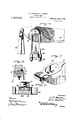
- FIG. 1 is a vertical section through a pit showing thevapplication of our improved .construction of suspension lbearings for platform scales in elevation;
- Fig. 2 is a vertical section taken ony the line'Q-Q of Fig. 1;
- Fig. 8 is a top planA 'view of one of the main levers;
- Fig. 4,' is a side elevation of one of the main levers;
- Fig. 5, is a perspective of the platform supporting member, main lever,'saddle block, U- shaped suspension member, connecting member, and. ball block member, detached: Fig.
- :6 is a section taken on the line 6 6 of Fig. '51, showing the adjustable bearing for the tip of the lever;
- Fig. 7 is a detailed perspective view of the butt of the lever;
- Fig. ⁇ 8 is
- the stand is provided with a head 3 having a recess in which is mounted a block 4: provided with a hardened steel bearing 5 upon which is mounted the fulcrum knifeedge pivot G of the main lever 7 said knifeedge pivot having a bearing throughout.
- each lever having a solid butt provided with a vertical opening 9, as clearly shown in Fig. 7 the opposite walls of which are provided with vertically disposed projections 10 for the purpose hereinafter fully described.
- the opposite end portion of the main lever 7 is substantlally T-shaped in cross section andl jecting extension lever knife-edge pivots 17 carried by the extension lever 18 which is in turn, Inounted in a suitable standard 19. It is, of course, understood that the extension 'lever is provided with oppositely disposed ⁇ knife-edge pivots upon which is mounted a similar support upon the opposite side to receive the tip of one of the other main levers.
- the recess 13 in the connecting block 14 is provided with a convex bottom 20 in order to allow the bearing block 12 to have a rocking movement therein, said block rocking to compensate for the'move- .ment of the respective levers in order to maintain the knife-edge ⁇ pivot in substantially the same common plane when the scale is in'operation.
- the manner of adjustably mounting the inverted U-shaped member l15 herein shown is to provide the legs of the inverted U- shaped member with threads which pass through openings 21 formed in the connecting block 14 and are adjustably held in position thereon, by lock nuts 22 by means of which.
- the connecting block H can be adjusted vertically so that in installing the main levers the knife-edge pivots carried by the tip end and butt of the lever can be adjusted to a common plane.
- a saddle block 24 having a hardened steel bearing surface contacting with the knife-edge pivot and provided with an annular groove 25 in its upper surface to receive the arch of a substantially inverted U-shaped suspension member 2G which extends through the lower end of the vertical opening of the lever 7 and is provided with threaded ends which extend through openings 27 formed in a ball block 28 which is adjustablv mounted upon the depending legs of the-inverted U-shaped member by loclcnuts 29 in order to allow the ball block to be adjusted vertically upon the legs for the purpose hereinafter fully described.
- the enlargements 10 formed in the open- -ing of the main lever form concentrated bearings for the sides of the saddle blocks in order to reduce the friction.
- the ball block 28 is provided with a semi-spherical projection 30 uponits upper surface extending into a similar-shaped recess 31 formed in the under side of the connecting member 32, asclearly shown in Fig. 1.
- Straddling the slotted portion of the lever is a platform supporting member 33 which is provided'with bifurcated legs 34 which embrace ⁇ vertical ribs 35 'formed on the top of the connecting member 32.
- said connecting member being provided with end extensions 3G in order to hold the legs of the platform supporting member in proper position upon the connecting member.
- a connecting block 14 upon the substantially universal connection is formed betweenthe ball block and connecting member of the platform supporting member by means of which the platform supporting member is allowed to swing freely with the movement of the platform without affecting the bearings of the levers which remain at rest when a vehicleor other object is passing on or off. of the platform. It will be seen thatthe thrust. imparted to the platformis compensated for by the vuniversal connection at this point and a suspension bearing is fo1n1ed,. ⁇ vhich allows the platform supporting member to be vertically adjusted.
- suspension bearing herein shown, enables the strain to be thrown indirectly upon the full length' of the load receiver pivot of the lever in such a manner that side strain is dispensed with and a load receiving bearing is constructed which receives the load in such a manner that all danger of any grinding of the bearings is dispensed with.
- the platform supporting member is connected to the platform girder 37 by bolts, as clearly shown, said girder extending longitudinally of the platform and yupon which v the usual deck or planking 38 is mounted ⁇ which is in horizontal alinement Withthe top. edge of the pit, as clearly shown in Fig. 1,I the edge of the pit being'reinforced, as clearly shown, to prevent chipping.
- Secured to the under side of the deck 38 to each side of the I beams 37 are platform beams 39 connected to the I beams by diagonal braces 40, said braces being preferably formed of angle irons whereby a rigid construction of underframing is formed which reduces the weight of construction and yet maintains the rigidity.
- a weighing scale the combination With ay lever having a pivot, a saddle block mounted upon said pivot, a U-shaped suspensionl member embracing said saddle block, a platform supporting member embracing said lever, a connecting member for said platform supporting 'member, and a ball block adjustably mounted upon said U- shaped suspension member having a universal connection With said connecting member.
- a weighing scale the combinationl with a lever'having a pivot, a saddle block mounted upon said pivot, a suspension member embracing said saddle block, a block adjustably mounted upon said suspension member, a connecting member mounted upon said block and extending. transversely of said lever and having a universal ⁇ movement upon said block, and a platform supporting versal connection with said platform supporting member, and means for adjusting said ball block.
- a platform supporting means for weighing scales comprising a platform supporting member having bifurcated legs, a connecting member provided with ribs over which said legs are mounted, an adjustable supporting block upon which said connecting member -is mounted, and suspension means 'for said adjustable supporting member.
- a platform supporting means for weighing scales comprising a platform supporting member having bifurcated legs, a connecting member provided with ribs over which said legs are mounted, said connecting member being provided with a socket, and an adjustable supporting block having a projection extending into said socket and upon which said connecting member is mounted for universal movement.
- a platform supporting means for weighing scales comprising a platform supporting member having depending bifurcated legs, a connecting member for said legs provided with ribs extending into the bifurcations of said legs, and an adjustable supporting block upon which said connecting member is mounted for universal movement.
- a lever having a tip-knife edge pivot, a rocking bearing having a universal movement for said pivot, adjustable supporting means for said rocking bearing, a saddle block carried by said supporting means, and a supporting pivot for said saddle block.
- a weighing sca-le the combination with a lever having a tip pivot, of a supporting pivot, a saddle block carried by said supporting pivot, a U-shaped suspension member embracing Said Saddle block, a connecting block adjustably mounted upon said U-shaped suspension member having a recess, and a bearing for said tip pivot mounted within said recess having universal movement independent of said U-shaped suspension member.
- a lever having a tip-knife edge pivot, a rocker bearing for said pivot, an adjustable support for said bearing in which said. bearing is-mounted to move independently of said support, a saddle block for supportingV said support, and a pivot upon which said saddle block is mounted.
- a weighing scale the combination with a lever having a vertical Opening across which extends a load-receiving knifeedge pivot ⁇ of a saddleblock mounted upon said load-receiving pivot, a U-shaped suspension member embracing said saddle block, a platform supporting member embracing said lever, a connecting member for said platform supporting member having a socket, a ball block-carried b v said U-shaped suspension member having a semi-spherical projection fitting within the socket of Said connecting member, and means for adjusting said ball block upon said U-shaped suspension member.
- a lever having a vertical opening provided with oppositely disposed enlargements, a load-receiver knife-edge pivot extending across said opening in alinement with said enlargement, a saddle block arranged within the opening of said lever upon said load-receiver pivot having contact with the enlargements of said opening, a U-shaped suspension member embracing said saddle block and depending from said lever, a platform supporting member embracing said lever having bifurcated legs, a connecting block provided with ribs to receive said bifurcated legs of said platform supporting member, means carried by Said connecting block for preventing lateral movement in respect to said platform supporting member, said'connecting block having a socket, and a ball block adjustably connected with said U-shaped suspension member having a projection extending within said socket.
- a-Weighing scale the combination with a lever provided with a solid butt having a vertically disposed opening formed therein, of a pivot extending across said opening midway of the width with said lever, a saddleblock mounted upon said pivot within said opening, a U-shaped suspension member cari'ied by said saddle block, a platform supporting member embracing said lever having depending legs provided with bil'ureated ends.
- connecting block provided with vertical ribs extending into the bifurcations ot said legs, said connecting block having a socket, a ball block carried b v said Ushaped suspension member, a projection carried b v said ball block extending into the socket ot' said connecting.member, and means tor adjusting the position ot' Said ballk block upon said U-shaped suspension member.
- a weighing scale the combination with a lever having ⁇ a load-receiving pivot disposed across a vertical opening formed therein, ot' a platform supporting member embracing said lever over Said opening otl said lever having a bearing upon said loadreceiving pivot.
- a U-shaped suspension member embracing said saddle block having threaded legs, a connecting member for said platform supporting member having a socket, aball block provided withopenings to receive the threaded legs of said U-shaped suspension member, nuts mounted upon said threaded legs for adjust-ing said ball block, and a segmental 'ball formed on said ball block extending into the socket of said connecting member.
- a weighing scale In a weighing scale, the combination with a lever having a vertical opening ⁇ formed therein, ot a knife-edge pivot ex tending across said opening ⁇ a saddle blockv4 mounted upon said pivot. a suspension member mounted upon said saddle block, a platform supporting member embracing said lever, a. connectinfT member for said ilatform sul'iporting member, and -a block adiustably mounted upon said suspension member upon which said connecting mem* ber 1s mounted for universal movement.
- a weighing scale In a weighing scale, the combination with a lever, of a U-shaped member carried b v said lever, an adjustable block carried by said U-shaped member, a connecting mem' ber mounted upon said block having a uni-V versal movement thereon, and a platform sui'iporting member mounted upon said connecting member.
- a lever having a vertical opening -disposed adjacent one end thereof, the opposite walls ot said lever being provided with vertically disposed enlargements, a
Landscapes
- Physics & Mathematics (AREA)
- General Physics & Mathematics (AREA)
- Details Of Cutting Devices (AREA)
Description
C. F. MOORE & E.- L. HUNTER WEIGHING SCALE. APPLICATION P ILED SEPT. 9. 1914.
1,167,31 1. Patented .1.1.4, 1916.
4 SHEETS-SHEET l. M y
C. F. MOORE & E. L. HUNTER.
WEIGHING scALE.
1 APPLICATION FILED SEPT-9. i914. Patented Jan. 4,
4 SHEETS-SHEET 2- mulini-iii `c. F. MOORE & E. L. HUNTER.
WEIGHING scALE. APPLICATION FILED SEPT- 9 1914.
Patented Jan. 4, 1916.
4 SHEETS-SHEET 3.
C. F. MOORE & E. L. HUNTER. WEIGHING SCALE.
APPLICATION FILED SEPT- 9. 1914.
Patented Jan. 4, 1916 4 SHEETS-SHEET 4.
7 zz/g- 6'. |l l lulu II I l mmh .76
*77v l 'HIM-1111;?in
'n 7 Z9 76 I g 74 I l Cao Kammer? CIHARLES F. MOORE AND EVERETT L. HUNTER, 0F BENNINGTON, ERMONT, ASSIGNORS V:TO A:11B-ENNINGr-'lONSCALE COMPANY; OFE-BENNINGTON, `VERMONT,` A CORPORATION To all whom t may concern Be it-known that we,` CHARLES F. MOORE and FivERFJi'r L. HUNTER, `citizens of the UnitedStates,.residing at Bennington, rin
the county of Bennington and State ofpVermeans for suspending the' platform `from the mainy levers in such amanner that the suspension means will have universal movement in orderto allow the suspension means A to move with 4the platform so as-to compensate for the end orv side thrust causedl by a vehicle or other movable object passing onto orofl' of the platform. Y i i Another object of the invention is to provide meansk 'for adjusting the tip bearing support and load receiver supporting-bearing to enable the levers to be readily installed -so that the knife-edge pivots thereof will befin a common plane.
' Another object of the invention is to provide a-novel form of nderframing for the platform by means of which `rigidity is obtained land a Ilconstruction' is'formed which allows the interior of the pitto have a clearance for theinspection of the lever constructions to facilitate the installation and re pairing of the scales.
' Another object of the invention is to provide a novelform of main lever in which the knife-edge pivots are arranged in a common "plane and are-so disposed that. an exceedingly strong and durable lever is formed in which the weight of theleveris decreased :f
without decreasing the strength thereof.l
l' Another and further object of the inven- 5- tion lis to provide a suspension bearing in which the knife-edge load receiver-pivot engages the full length of the saddleblock bearingupon which is mounted, a substantially inverted U-shaped suspension member `having avball block adj ustably'carried thereby which in turn has a universal-connection Specification ofilettersatent.
.versal or-rocking movement. l
' wmGiinv-SCALE.
ratentea aan. fr, 1916.
Application/ined sept'eibere'flemf samasm.
can be adjusted same,said adjustable bearing having a uni- Another andfurther ob'ect of the invention is to provide a platform scale construction which is simple and'y cheap and one :which can be readily set lup inthe pit so as to obtain quickly, perfect adjustment of the respective 'levers in order'to obtain the de- .sired result. l f
Other and further objects and' advantages of the invention will `be hereinafter set forth with the platform supporting member enwgagin'g the platform; framing, in'such` a manner that the platform -to a level planen.: Another'object of the invention is to pro- .vide an adjustable bearing for the knifeedge pivoty at the 'tip' of the lever in `order tol fallow thev lever to be leveled in installing the land the novelv features thereof defined by v :the appended claims. 1 1
y#In the drawings-Figure 1 is a vertical section through a pit showing thevapplication of our improved .construction of suspension lbearings for platform scales in elevation; Fig. 2, is a vertical section taken ony the line'Q-Q of Fig. 1; Fig. 8 is a top planA 'view of one of the main levers; Fig. 4,'is a side elevation of one of the main levers; Fig. 5, is a perspective of the platform supporting member, main lever,'saddle block, U- shaped suspension member, connecting member, and. ball block member, detached: Fig.
:6, isa section taken on the line 6 6 of Fig. '51, showing the adjustable bearing for the tip of the lever; Fig. 7, is a detailed perspective view of the butt of the lever; Fig. `8, is
a detailed vertical section through the upper :portion of the fulcrum stand and bearing: :and Fig. =9, is a detailed section through the lever tip supporting bearing.
Like numerals of reference refer to like parts in the several figures of the drawings. In the drawings,1 indicatesthe concrete. construction of a scale pit in which is ar'- ranged a series of yfulcrum'sta'nds 2,'and while we have only shown one ofv these stands, it is of course understood that four orlmore main levers are employed, and a de- -scription of one will be sufficient for all.
The stand is provided with a head 3 having a recess in which is mounted a block 4: provided with a hardened steel bearing 5 upon which is mounted the fulcrum knifeedge pivot G of the main lever 7 said knifeedge pivot having a bearing throughout. its
length upon the bearing block ofthe fulcrum stand and is prevented from moving sidewise upon the bearing block by end projections 8, as shown in Fig. 8.
In constructing a complete scale in accordance with our invention, four or more levers are employed, each lever having a solid butt provided with a vertical opening 9, as clearly shown in Fig. 7 the opposite walls of which are provided with vertically disposed projections 10 for the purpose hereinafter fully described. The opposite end portion of the main lever 7 is substantlally T-shaped in cross section andl jecting extension lever knife-edge pivots 17 carried by the extension lever 18 which is in turn, Inounted in a suitable standard 19. It is, of course, understood that the extension 'lever is provided with oppositely disposed `knife-edge pivots upon which is mounted a similar support upon the opposite side to receive the tip of one of the other main levers. The recess 13 in the connecting block 14 is provided with a convex bottom 20 in order to allow the bearing block 12 to have a rocking movement therein, said block rocking to compensate for the'move- .ment of the respective levers in order to maintain the knife-edge `pivot in substantially the same common plane when the scale is in'operation. l
The manner of adjustably mounting the inverted U-shaped member l15 herein shown, is to provide the legs of the inverted U- shaped member with threads which pass through openings 21 formed in the connecting block 14 and are adjustably held in position thereon, by lock nuts 22 by means of which. the connecting block H can be adjusted vertically so that in installing the main levers the knife-edge pivots carried by the tip end and butt of the lever can be adjusted to a common plane.` ln installing the levers the fulcrum stand is placed in position first and the main lever with its knife-edge bearing is placed in position upon the bearing of the fulcrum stand. It is. of course, understood that the extension 'lever has been placed in position upon its stand with its supporting means. The tip knife-edge pivot of the main lever is then placed in position upon the supporting bearing of the connecting block and by adjusting the nuts 22, the tip knife-edge pivot can be moved into horizontal alinement with the fulcrum knife-edge pivot of the butt j.'
' which is mounted a saddle block 24 having a hardened steel bearing surface contacting with the knife-edge pivot and provided with an annular groove 25 in its upper surface to receive the arch of a substantially inverted U-shaped suspension member 2G which extends through the lower end of the vertical opening of the lever 7 and is provided with threaded ends which extend through openings 27 formed in a ball block 28 which is adjustablv mounted upon the depending legs of the-inverted U-shaped member by loclcnuts 29 in order to allow the ball block to be adjusted vertically upon the legs for the purpose hereinafter fully described. n
The enlargements 10 formed in the open- -ing of the main lever form concentrated bearings for the sides of the saddle blocks in order to reduce the friction..
The ball block 28 is provided with a semi-spherical projection 30 uponits upper surface extending into a similar-shaped recess 31 formed in the under side of the connecting member 32, asclearly shown in Fig. 1. Straddling the slotted portion of the lever is a platform supporting member 33 which is provided'with bifurcated legs 34 which embrace `vertical ribs 35 'formed on the top of the connecting member 32. said connecting member being provided with end extensions 3G in order to hold the legs of the platform supporting member in proper position upon the connecting member. It
'*Will be seen from this construction that a connecting block 14: upon the substantially universal connection is formed betweenthe ball block and connecting member of the platform supporting member by means of which the platform supporting member is allowed to swing freely with the movement of the platform without affecting the bearings of the levers which remain at rest when a vehicleor other object is passing on or off. of the platform. It will be seen thatthe thrust. imparted to the platformis compensated for by the vuniversal connection at this point and a suspension bearing is fo1n1ed,.\vhich allows the platform supporting member to be vertically adjusted. It will also be n-oted that the construction of suspension bearing herein shown, enables the strain to be thrown indirectly upon the full length' of the load receiver pivot of the lever in such a manner that side strain is dispensed with and a load receiving bearing is constructed which receives the load in such a manner that all danger of any grinding of the bearings is dispensed with.
The platform supporting member is connected to the platform girder 37 by bolts, as clearly shown, said girder extending longitudinally of the platform and yupon which v the usual deck or planking 38 is mounted `which is in horizontal alinement Withthe top. edge of the pit, as clearly shown in Fig. 1,I the edge of the pit being'reinforced, as clearly shown, to prevent chipping. Secured to the under side of the deck 38 to each side of the I beams 37 are platform beams 39 connected to the I beams by diagonal braces 40, said braces being preferably formed of angle irons whereby a rigid construction of underframing is formed which reduces the weight of construction and yet maintains the rigidity. By this construction, the heavy underframing noW employed with previous constructions of scales is dispensed With and a construction is produced which has all of the advantages of previous constructions and at the same time, allowsmore room Within the pit in order to facilitate the installing of the platform and the repairingof the parts of the scale proper. In constructing the platform of the scale, two Il beams and four platform beams are employed, the centerplatform beams, not
shown, being connected together by angle irons 41. i
With a construction of suspension bearings and lever mounts as herein shown, it is not essential to provide platform-controlling means. However, We have shown the I beams 'provided with U-shaped brackets 42 to which are connected controlling members 43 mounted in suitable bearings 44 carried by the sides of the pit.
From the foregoing description, it will be seen that we have provided a novel form of Isuspension bearings and main levers for a platform scale in Which means is provided for adjusting the platform supporting member in order to adjust the platform so as to bring the tread surface thereof into horizontal alinelnent with the tread surface of the pit.
It will also be seen that We have provided v means for adjusting the tip knife-edge pivots of the levers into a common plane.
lVhile We have shown and described a' construction which is especially adapted to be used in connection with platform scales, We do not wish to limitv ourselves to the use of the supporting bearings and platform supporting members toany form of scale, as it might be found that the construction as herein described, could be used in connection with various othery forms of scale Without departing from the spirit of our invention.
I"We claim:
1. In Va Weighing scale, the combination with a lever, of a load-receiver pivot mounted Within said lever, a saddle block mounted upon said load-receiver pivot, a- U-shaped suspension member embracing said saddle block, a platform supporting member` embracing said lever, a connecting member for said platform supporting member, a ball block carried by said U-shaped suspension member having a universal connection With said platform connecting member, and
- means for adjusting said ball block.
2. In a weighing scale, the combination With ay lever having a pivot, a saddle block mounted upon said pivot, a U-shaped suspensionl member embracing said saddle block, a platform supporting member embracing said lever, a connecting member for said platform supporting 'member, and a ball block adjustably mounted upon said U- shaped suspension member having a universal connection With said connecting member.
3. In a Weighing scale, the combination with a lever having a vload-receiver pivot, of a saddle block: mounteduponsaid load-receiver pivot, a suspension member vembracing said saddle block, a platform supporting member embracing said lever, adjust-able supporting means carried by said suspension lnember, and a connecting member for said platform supporting member having a universal connection With said supporting lIlelIlS.
4. In a Weighing scale, the combination with a lever having a pivot, a saddle block mounted upon said pivot, asuspension member embracing said saddle block, a block adjustably mounted upon said suspension member, a connecting member mounted upon said block and having a universal movement thereon, and a platform supporting member embracing said lever and mounted. upon said connecting member.
5. In a weighing scale, the combinationl with a lever'having a pivot, a saddle block mounted upon said pivot, a suspension member embracing said saddle block, a block adjustably mounted upon said suspension member, a connecting member mounted upon said block and extending. transversely of said lever and having a universal` movement upon said block, and a platform supporting versal connection with said platform supporting member, and means for adjusting said ball block.
7. A platform supporting means for weighing scales, comprising a platform supporting member having bifurcated legs, a connecting member provided with ribs over which said legs are mounted, an adjustable supporting block upon which said connecting member -is mounted, and suspension means 'for said adjustable supporting member.
S. A platform supporting means for weighing scales, comprising a platform supporting member having bifurcated legs, a connecting member provided with ribs over which said legs are mounted, said connecting member being provided with a socket, and an adjustable supporting block having a projection extending into said socket and upon which said connecting member is mounted for universal movement.
9. A platform supporting means for weighing scales, comprising a platform supporting member having depending bifurcated legs, a connecting member for said legs provided with ribs extending into the bifurcations of said legs, and an adjustable supporting block upon which said connecting member is mounted for universal movement.
10. In a weighing machine, a lever having a tip-knife edge pivot, a rocking bearing having a universal movement for said pivot, adjustable supporting means for said rocking bearing, a saddle block carried by said supporting means, and a supporting pivot for said saddle block.
1l. In a Weighing scale, the combination with a main lever having a tip pivot, of a supporting pivot, a saddle block carried by said supporting pivot, a U-shaped suspension member embracing said saddle block, an adjustable connecting block carried by said suspension member, and a tip pivot bearing carried by said connecting block having a universal movement independent af said U-shaped suspension member.
12. In a weighing sca-le, the combination with a lever having a tip pivot, of a supporting pivot, a saddle block carried by said supporting pivot, a U-shaped suspension member embracing Said Saddle block, a connecting block adjustably mounted upon said U-shaped suspension member having a recess, and a bearing for said tip pivot mounted within said recess having universal movement independent of said U-shaped suspension member.
13. In a weighing scale, the combination with a supporting pivot, a saddle block mounted upon said pivot, a suspension membcr embracing said saddle block, an adjustable member carried by said suspension member provided with a recess, and a rocker bearing mounted in 'said recess and capable of moving independently of said suspension member. i
14;. A lever, having a tip-knife edge pivot, a rocker bearing for said pivot, an adjustable support for said bearing in which said. bearing is-mounted to move independently of said support, a saddle block for supportingV said support, and a pivot upon which said saddle block is mounted.
15. In a weighing scale, the combination with a lever having a vertical Opening across which extends a load-receiving knifeedge pivot` of a saddleblock mounted upon said load-receiving pivot, a U-shaped suspension member embracing said saddle block, a platform supporting member embracing said lever, a connecting member for said platform supporting member having a socket, a ball block-carried b v said U-shaped suspension member having a semi-spherical projection fitting within the socket of Said connecting member, and means for adjusting said ball block upon said U-shaped suspension member.
1G. In a weighing scale, the combination with a lever having a vertical opening formed therein, of a knife-edge pivot extending across said opening, a saddle block bearing mounted upon said knife-edge pivot` a U-shaped suspension member mounted upon said saddle block, a platform supporting member embracing said lever having' bifurcated ends` a connecting block provided with ribs to receive said bifurcated end, said connecting block having a socket, and a ball block adjustably 'connected with Said U- shaped suspension member having arsemispherical shaped projection fitting Within the socket of said connecting member.
17. In a scale` a lever having a vertical opening provided with oppositely disposed enlargements, a load-receiver knife-edge pivot extending across said opening in alinement with said enlargement, a saddle block arranged within the opening of said lever upon said load-receiver pivot having contact with the enlargements of said opening, a U-shaped suspension member embracing said saddle block and depending from said lever, a platform supporting member embracing said lever having bifurcated legs, a connecting block provided with ribs to receive said bifurcated legs of said platform supporting member, means carried by Said connecting block for preventing lateral movement in respect to said platform supporting member, said'connecting block having a socket, and a ball block adjustably connected with said U-shaped suspension member having a projection extending within said socket.
18. In a-Weighing scale, the combination with a lever provided with a solid butt having a vertically disposed opening formed therein, of a pivot extending across said opening midway of the width with said lever, a saddleblock mounted upon said pivot within said opening, a U-shaped suspension member cari'ied by said saddle block, a platform supporting member embracing said lever having depending legs provided with bil'ureated ends. a connecting block provided with vertical ribs extending into the bifurcations ot said legs, said connecting block having a socket, a ball block carried b v said Ushaped suspension member, a projection carried b v said ball block extending into the socket ot' said connecting.member, and means tor adjusting the position ot' Said ballk block upon said U-shaped suspension member.
1t). ln a weighing scale, the combination with a lever having` a load-receiving pivot disposed across a vertical opening formed therein, ot' a platform supporting member embracing said lever over Said opening otl said lever having a bearing upon said loadreceiving pivot. a U-shaped suspension member embracing said saddle block having threaded legs, a connecting member for said platform supporting member having a socket, aball block provided withopenings to receive the threaded legs of said U-shaped suspension member, nuts mounted upon said threaded legs for adjust-ing said ball block, and a segmental 'ball formed on said ball block extending into the socket of said connecting member. y
20. ln a weighing scale, a lever having a pivot, a rocker bearing for saidpivot having universal movement, and an adjustable support lor said rocker bearing.
21.. ln a weighing scale. the combination with a lever having a vertical openin, r across which extends a. load receiver knife-edge pivot. of a saddle block mounted upon said load-receiver pivot, a U-shaped suspensionV member embracing said saddle block, a platform supporting member.embracing said lever, a connecting,` member for said platform supporting member, and a `block adjustably mounted upon said Ushaped suspension member upon .which said connecting member is mounted for universal movement.
In a weighing scale, the combination with a lever having a vertical opening` formed therein, ot a knife-edge pivot ex tending across said opening` a saddle blockv4 mounted upon said pivot. a suspension member mounted upon said saddle block, a platform supporting member embracing said lever, a. connectinfT member for said ilatform sul'iporting member, and -a block adiustably mounted upon said suspension member upon which said connecting mem* ber 1s mounted for universal movement.
23. In a platform scale, the combination with a. series ot main levers having fixed fulerum bearings for the fulcrum knife-edge opposing walls ot' which are centrally en-y larged. of a' haul-receiver knife-edge pivot extending through the walls of said opening in alinement with said enlargements, a saddle vblock itting within the openingof said levery and contacting with the enlargements thereof, and load-supporting means carriedb v said saddle block.
In a weighing scale, the combination with a lever, of a U-shaped member carried b v said lever, an adjustable block carried by said U-shaped member, a connecting mem' ber mounted upon said block having a uni-V versal movement thereon, and a platform sui'iporting member mounted upon said connecting member.
QG. In a weighing scale, the combination with a lever, of `a U-shaped member carried b v said lever, a block adjustably mounted upon said U-sbaped member, a connecting member mounted upon said block, and' a platform supporting member mounte'd'upon saidconnecting member. Y n
27. A lever, having a vertical opening -disposed adjacent one end thereof, the opposite walls ot said lever being provided with vertically disposed enlargements, a
load knife-edge pivot disposed across said openii'ig in alinemeiit with said enlargements, a saddle block arranged within said opening having its sides contacting With the enlargement thereof, and U-shaped suspen-f sion means carried b v said saddle block.
In testimony whereof we atiix our signatures in presence. ot two witntsses.
Cll'iU-LS F. MOORE. lffEllhTiflf f HUNTER. 'itnesses C. L. llotunxT E. l'l. HOLDEN.
Copies of this patent may be obtained for five cents each, by addressing the Commissioner of Patents,
Washington, D. C.
Priority Applications (1)
| Application Number | Priority Date | Filing Date | Title |
|---|---|---|---|
| US86090014A US1167311A (en) | 1914-09-09 | 1914-09-09 | Weighing-scale. |
Applications Claiming Priority (1)
| Application Number | Priority Date | Filing Date | Title |
|---|---|---|---|
| US86090014A US1167311A (en) | 1914-09-09 | 1914-09-09 | Weighing-scale. |
Publications (1)
| Publication Number | Publication Date |
|---|---|
| US1167311A true US1167311A (en) | 1916-01-04 |
Family
ID=3235330
Family Applications (1)
| Application Number | Title | Priority Date | Filing Date |
|---|---|---|---|
| US86090014A Expired - Lifetime US1167311A (en) | 1914-09-09 | 1914-09-09 | Weighing-scale. |
Country Status (1)
| Country | Link |
|---|---|
| US (1) | US1167311A (en) |
Cited By (3)
| Publication number | Priority date | Publication date | Assignee | Title |
|---|---|---|---|---|
| US2742330A (en) * | 1952-05-21 | 1956-04-17 | August Sauter K G | Bearing for balance beams capable of swinging in all directions |
| US2869855A (en) * | 1957-06-05 | 1959-01-20 | L R Murphy Scale Company | Extensible scale platform for weighing trucks and the like |
| US4609062A (en) * | 1985-07-19 | 1986-09-02 | Colt Industries Operating Corp. | Heavy-duty industrial weighing scale |
-
1914
- 1914-09-09 US US86090014A patent/US1167311A/en not_active Expired - Lifetime
Cited By (3)
| Publication number | Priority date | Publication date | Assignee | Title |
|---|---|---|---|---|
| US2742330A (en) * | 1952-05-21 | 1956-04-17 | August Sauter K G | Bearing for balance beams capable of swinging in all directions |
| US2869855A (en) * | 1957-06-05 | 1959-01-20 | L R Murphy Scale Company | Extensible scale platform for weighing trucks and the like |
| US4609062A (en) * | 1985-07-19 | 1986-09-02 | Colt Industries Operating Corp. | Heavy-duty industrial weighing scale |
Similar Documents
| Publication | Publication Date | Title |
|---|---|---|
| US1167311A (en) | Weighing-scale. | |
| US3047084A (en) | Spring balance or weighing device | |
| US4010811A (en) | Platform scale | |
| US115190A (en) | Improvement in platform-scales | |
| US3658144A (en) | Weight platform apparatus in a weighing machine | |
| US833922A (en) | Balance or weighing apparatus of the pendulum type. | |
| US1954205A (en) | Weighing scale | |
| US1627702A (en) | Platform lever mechanism for scales | |
| US1627124A (en) | Weighing machine | |
| US1213295A (en) | Scale-check device. | |
| US1222202A (en) | Hopper-scale. | |
| US2201368A (en) | Weighing scale | |
| US1065844A (en) | Balance. | |
| US600021A (en) | Weighing-machine bearing | |
| US1511531A (en) | Scale | |
| US1404809A (en) | Check-link mechanism | |
| US2608448A (en) | Knife edge pivot construction | |
| US1385592A (en) | Scale | |
| US1489368A (en) | Scale | |
| US163060A (en) | Improvement in weighing-scales | |
| US2142424A (en) | Scale | |
| US3097715A (en) | Weighing scale | |
| US52653A (en) | Improvement in machines for determining the load of car-axles | |
| FI70747C (en) | ELECTRONIC VAOG | |
| US2279678A (en) | Weighing scale |