US11672736B2 - Pill cutter and method for using thereof - Google Patents
Pill cutter and method for using thereof Download PDFInfo
- Publication number
- US11672736B2 US11672736B2 US17/167,748 US202117167748A US11672736B2 US 11672736 B2 US11672736 B2 US 11672736B2 US 202117167748 A US202117167748 A US 202117167748A US 11672736 B2 US11672736 B2 US 11672736B2
- Authority
- US
- United States
- Prior art keywords
- pill
- pressing plate
- bottom case
- shield plate
- cutter
- Prior art date
- Legal status (The legal status is an assumption and is not a legal conclusion. Google has not performed a legal analysis and makes no representation as to the accuracy of the status listed.)
- Active, expires
Links
Images




Classifications
-
- A—HUMAN NECESSITIES
- A61—MEDICAL OR VETERINARY SCIENCE; HYGIENE
- A61J—CONTAINERS SPECIALLY ADAPTED FOR MEDICAL OR PHARMACEUTICAL PURPOSES; DEVICES OR METHODS SPECIALLY ADAPTED FOR BRINGING PHARMACEUTICAL PRODUCTS INTO PARTICULAR PHYSICAL OR ADMINISTERING FORMS; DEVICES FOR ADMINISTERING FOOD OR MEDICINES ORALLY; BABY COMFORTERS; DEVICES FOR RECEIVING SPITTLE
- A61J7/00—Devices for administering medicines orally, e.g. spoons; Pill counting devices; Arrangements for time indication or reminder for taking medicine
- A61J7/0007—Pill breaking or crushing devices
Definitions
- the present disclosure relates to a medical auxiliary device, and more particularly to a pill cutter and a method for using thereof.
- the medicine and the health food can be taken orally, by injection, or applied externally, etc.
- the oral medicine is a kind of medicine that is easy to preserve and carry, so the oral medicine is a commonly used kind of medicine.
- the oral medicine has the forms of pills, capsules, powders, etc.
- the pill is molded to a shape of round, ellipse, or polygon, which is easy to swallow. As the pill is easier to preserve under various external environments, the pill is a most used kind of medicine.
- the pill can be cut by a pill cutter with a blade and the blade must be very sharp. Therefore, the pill is normally cut by a high-quality metal cutter, which causes a safety problem that the user may be scratched by an exposed blade when putting the pill in the pill cutter. The safety of the pill cutter is reduced.
- the existing pill deblister device and the pill cutter are independent from each other, the user needs to remove the pill and then put the pill in the pill cutter, the integral operation time of cutting the pill is increased, and the possibility of pill contamination is increased, which will cause negative effect to the patients.
- a pill cutter for cutting pills including: a bottom case; a pressing plate, rotatably connected to the bottom case and provided with a blade; and a shield plate, rotatably connected to the bottom case and provided with a slit; wherein, the shield plate is located between the pressing plate and the bottom case, when the pressing plate rotates relative to the bottom case, the pressing plate cooperates with the shield plate, so that the blade at least has a protected state and a pill-cutting state, in the protected state, the blade is positioned between the shield plate and the pressing plate after the pressing plate and the shield plate are separated from each other, and in the pill-cutting state, the blade passes through the slit and reaches the bottom case.
- a method for using the pill cutter including the following steps:
- a method for using the pill cutter including the following steps:
- the pill deblister column removes a pill from the pill board, then the pill moves through the channel towards the positioning platform and is cut by the fallen blade.
- FIG. 1 is a stereogram of a pill cutter of the present disclosure.
- FIG. 2 is decomposition view of the pill cutter of the present disclosure.
- FIG. 3 is a stereogram of a bottom case of the pill cutter of the present disclosure.
- FIG. 4 is stereogram of a pressing plate of the pill cutter of the present disclosure.
- FIG. 5 is a stereogram of a shield plate of the pill cutter of the present disclosure.
- FIG. 6 is top view of the shield plate of the pill cutter of the present disclosure.
- FIG. 7 is a schematic view of the pill cutter in a pill-cutting state of the present disclosure.
- FIG. 8 is schematic view of the pill cutter in a protected state of the present disclosure.
- FIG. 9 is a flow chart of a method for using the pill cutter of the present disclosure.
- FIG. 10 is top view of the pill cutter of the present disclosure.
- FIG. 11 is a section view along a section line A-A in FIG. 10 of the pill cutter in the pill-cutting state.
- FIG. 12 is a section view along a section line B-B in FIG. 10 of the pill cutter in the pill-cutting state.
- FIG. 13 is a section view along a section line A-A in FIG. 10 of the pill cutter in a first rotation stage.
- FIG. 14 is a section view along a section line B-B in FIG. 10 of the pill cutter in a first rotation stage.
- FIG. 15 is a section view along a section line A-A in FIG. 10 of the pill cutter in a second rotation stage.
- FIG. 16 is a section view along a section line B-B in FIG. 10 of the pill cutter in a second rotation stage.
- FIG. 17 is a section view along a section line A-A in FIG. 10 of the pill cutter in the protected state.
- FIG. 18 is a section view along a section line B-B in FIG. 10 of the pill cutter in the protected state.
- FIG. 19 is a flow chart of another kind of method for using the pill cutter.
- FIGS. 20 - 24 are schematic views of the steps of another kind of method for using the pill cutter.
- FIG. 1 is a stereogram of a pill cutter of the present disclosure.
- FIG. 2 is decomposition view of the pill cutter of the present disclosure.
- FIG. 3 is a stereogram of a bottom case of the pill cutter of the present disclosure.
- FIG. 4 is stereogram of a pressing plate of the pill cutter of the present disclosure.
- FIG. 5 is a stereogram of a shield plate of the pill cutter of the present disclosure.
- FIG. 6 is top view of the shield plate of the pill cutter of the present disclosure.
- a pill cutter of the present disclosure includes: a bottom case 1 , a pressing plate 2 , and a shield plate 3 .
- the pressing plate 2 is rotatably connected to the bottom case 1 .
- a side of the pressing plate 2 facing the bottom case 1 is provided with a blade slot 24 , and a blade 4 is mounted in the blade slot 24 .
- the shield plate 3 is rotatably connected to the bottom case 1 and provided with a slit 31 .
- the shield plate 3 is located between the pressing plate 2 and the bottom case 1 and includes a shield plate body 30 . When the pressing plate 2 rotates relative to the bottom case 1 , the pressing plate 2 cooperates with the shield plate 3 , so that the blade 4 at least has a protected state and a pill-cutting state.
- the blade 4 In the protected state, the blade 4 is positioned between the shield plate 3 and the pressing plate 2 after the pressing plate 2 and the shield plate 3 are separated from each other, and in the pill-cutting state, the blade 4 passes through the slit 31 of the shield plate 3 and reaches the bottom case 1 . Therefore, when the pill cutter is opened, the shield plate 3 can be used for shield the blade 4 automatically during the rotation process of the pressing plate 2 to prevent the blade 4 from being exposed in the protected state, and in the pill-cutting state, the blade 4 can pass through the shield plate 3 to cut the pills.
- the shield plate doesn't always rotate together with the pressing plate.
- the pressing plate 2 cooperating with the shield plate 3 includes the pressing plate 2 rotating alone while the shield plate 3 staying static relative to the bottom case 1 in a first cooperation state and the shield plate 3 rotating together with the pressing plate 2 in a second cooperation state. Therefore, no matter in the opening process or in the closing process for cutting the pills, the pressing plate 2 and the shield plate 3 doesn't always rotate together.
- the pressing plate 2 and the shield plate 3 have a first cooperation state that the shield plate 3 doesn't rotate together with the pressing plate 2 and a second cooperation state that the shield plate 3 rotates together with the pressing plate 2 .
- the shield plate 3 stays static relative to the bottom case, that is, the shield plate 3 and the pressing plate 2 are in the first cooperation state.
- the pressing plate 2 rotates alone relative to the bottom case 1 and the rotation angle of the pressing plate 2 is larger than or equal to the preset angle, the pressing plate 2 abuts and drives the shield plate 3 , the pressing plate 2 and the shield plate 3 rotate synchronously and respectively around two different rotating shafts, that is, the shield plate 3 and the pressing plate 2 are in the second cooperation state.
- the pressing plate 2 and the shield plate 3 rotate around two different rotating shafts at a same rotation velocity, but the present disclosure is not limited to this.
- a first space 5 is formed between the pressing plate 2 and the shield plate 3
- the blade 4 in the protected state is integrally accommodated in the first space 5
- a second space 6 is formed between the shield plate 3 and the bottom case 1 , at least a part of the blade 4 in the pill-cutting state enters the second space 6 from the first space 5 through the slit 31 .
- the present disclosure is not limited to this.
- a first pivoting portion 11 and a second pivoting portion 12 are provided on a first end 1 A of the bottom case 1 .
- a first end 2 A of the pressing plate 2 is rotatably connected to the first pivoting portion 11 through a first rotating shaft 21 .
- the first end 2 A of the pressing plate 2 is provided with a second driving portion 23 .
- a first end 3 A of the shield plate 3 is rotatably connected to the second pivoting portion 12 through a second rotating shaft 34 .
- the first end 3 A of the shield plate 3 is provided with a second contacting portion 33 .
- a second gap D is formed between the second driving portion 23 and the second contacting portion 33 .
- the second gap D decreases until the second driving portion 23 abuts the second contacting portion 33 , but the present disclosure is not limited to this.
- the bottom case 1 is further provided with a pill container 15 for storing the pill, but the present disclosure is not limited to this.
- a first end 2 A of the pressing plate 2 is further provided with a first driving portion 22 , the first driving portion 22 is closer to first end 2 A of the pressing plate 2 than the second driving portion 23 .
- the first end 3 A of the shield plate 3 is further provided with a first contacting portion 32 , the first contacting portion 32 is closer to the first end 3 A of the shield plate 3 than the second contacting portion 33 .
- the first driving portion 22 abuts the first contacting portion 32 to drive the shield plate 3 to rotate around the second rotating shaft 34 .
- the angle between the pressing plate 2 and the bottom case 1 during the first rotation stage is smaller than the angle between the pressing plate 2 and the bottom case 1 during the second rotation stage.
- a first gap C is formed between the first driving portion 22 and the first contacting portion 32 , during an initial rotation process of the pressing plate 2 , as the first gap C exists, the first driving portion 22 is not in contact with the first contacting portion 32 , the pressing plate 2 rotates alone and the shield plate 3 stays static. As the rotation angle of the pressing plate 2 relative to the bottom case 1 increases, the first gap C decreases, until the first driving portion 22 abuts the first contacting portion 32 . At this time, the pressing plate 2 can drive the shield plate 3 to rotate synchronously, to realize a transformation between the first rotation stage and the second rotation stage. But the present disclosure is not limited to this.
- the first driving portion 22 and the first contacting portion 32 are separated from each other.
- the second driving portion 23 and the second contacting portion 33 are separated from each other.
- the pressing plate 2 can continue driving the shield plate 3 to rotate synchronously (but with a contacting portion different from the above), until the pill cutter is completely opened.
- the first rotation stage and the second rotation stage have two different time ranges, and the time range of the first rotation stage is before the time range of the second rotation stage in time sequence.
- the first rotation stage is a stage when the pressing plate 2 is just separated from the bottom case 1 and the rotation angle of the pressing plate 2 is in a smaller angle range
- the second rotation stage is a stage when the pressing plate 2 continues rotating relative to the bottom case 1 and the rotation angle of the pressing plate 2 increases to a larger angle range.
- the angle between the pressing plate 2 and the bottom case 1 is within a smaller angle range of 0°-30°
- the angle between the pressing plate 2 and the bottom case 1 is within a large angle range of 31°-80°.
- the present disclosure is not limited to this.
- the two groups of the driving components are used to satisfy the largest opening angle of the pill crusher, and provide a damping for keeping the largest opening angle of the pill cutter in the protected state, so that the pill cutter is easier to be kept at this state.
- the two groups of the driving components are also used to satisfy the rigidity required for cutting the pills in the pill-cutting state, but the present disclosure is not limited to this.
- the first rotation stage and the second rotation stage can also be realized only by a third driving portion of the pressing plate, a third contacting portion of the shield plate (the pressing plate no longer includes the first driving portion and the second driving portion, and the shield plate no longer includes the first contacting portion and the second contacting portion), and a third gap between the third driving portion and the third contacting portion.
- the pressing plate rotates alone, as the third gap exists, the third driving portion moves and is not in contact with the third contacting portion.
- the second rotation stage begins, and the pressing plate rotates with the shield plate synchronously, but the present disclosure is not limited to this.
- the slit 31 extends from the second end 3 B of the shield plate 3 departing from the rotating shaft of the shield plate 3 towards the first end 3 A.
- the second end 2 B of the pressing plate 2 departing from the rotating shaft of the pressing plate 2 is provided with a pill deblister column 26 .
- the second end 1 B of the bottom case 1 departing from the rotating shaft is provided with a pill deblister hole 14 used for the pill deblister column 26 going through.
- the bottom case 1 is further provided with a channel 16 , the channel 16 connects a lower part of the pill deblister hole 14 to a positioning platform 13 .
- the channel 16 inclines from the lower part of the pill deblister hole 14 towards the positioning platform 13 , to guide the pills to move towards the positioning platform 13 . Therefore, the pill deblister operation and the pill-cutting operation are unified, and can be accomplished by one closing action, contact opportunities between the user and the pill are largely reduced.
- the positioning platform 13 supports the pills and limits the positions of the pills using its side wall, but the present disclosure is not limited to this.
- FIG. 7 is a schematic view of the pill cutter in a pill-cutting state of the present disclosure.
- FIG. 8 is schematic view of the pill cutter in a protected state of the present disclosure.
- the pressing plate 2 is provided with a side wall 25 , the side wall 25 and at least a part of the pressing plate 2 together form an accommodation slot 27 for accommodating the shield plate 3 in the pill-cutting state.
- the accommodation slot 27 has a slot opening and an end portion G.
- the end portion G is a furthest portion of the slot opening from a rotating shaft of the pressing plate 2 . That is, the end portion G has a larger distance from the rotating shaft of the pressing plate 2 than other portions of the slot opening.
- An effective opening length of the accommodation slot 27 is a distance H from the end portion G to an axle center of a rotating shaft of the shield plate 3 .
- the shield plate 3 is capable of passing through the slot opening to enter or exit from the accommodation slot 27 .
- the distance H between the end portion G and the axle center F of the rotating shaft of the shield plate 3 is smaller than the length of the shield plate 2 , that is, the effective opening length is smaller than the length of the shield plate 3 , the end portion G blocks the shield plate 3 from returning to the accommodation slot 27 .
- the blade (not shown in FIG. 7 and FIG. 8 ) won't be exposed from the slit 31 .
- the axle center F of the second rotating shaft 34 is located within an area centered on the axle center E of the first rotating shaft 21 , and a radius of the area is equal to a distance from the end portion G of the slot opening of the accommodation slot 27 furthest from the rotating shaft of the pressing plate 2 and the first rotating shaft 21 .
- the pressing plate 2 and the shield plate 3 rotate around two different rotating shafts, respectively, the position of the accommodation slot 27 relative to the shield plate 3 can be changed. Based on the preset sizes, the first space 5 is larger than the blade 4 . Therefore, when the pill cutter is opened, the blade 4 is in the protected state, the end portion G blocks the shield plate 3 from returning to the accommodating slot 27 .
- the blade 4 is integrally accommodated in the first space 5 formed between the pressing plate 2 and the shield plate 3 .
- the shield plate 3 isolates the first space 5 and the second space 6 , the use's hand puts the pills only in the second space 6 , can't touch the blade 4 accommodated in the first space 5 , and won't get hurt by the blade 4 accommodated in the first space 5 at all.
- FIG. 9 is a flow chart of a method for using the pill cutter of the present disclosure. As shown in FIG. 9 , the method for using the pill cutter of the present disclosure includes the following steps:
- the blade can be accommodated between the shield plate and the pressing plate when the pill is put in the opened pill cutter, to prevent the blade from being exposed and scratching the user.
- FIG. 10 is top view of the pill cutter of the present disclosure.
- FIG. 11 is a section view along a section line A-A in FIG. 10 of the pill cutter in the pill-cutting state.
- FIG. 12 is a section view along a section line B-B in FIG. 10 of the pill cutter in the pill-cutting state.
- the shield plate 3 can enter the accommodating slot 27 , so that the blade 4 on the pressing plate 2 passes through the slit 31 of the shield plate 3 to reach the bottom case 1 .
- the pressed-down shield plate 3 contributes to cooperating with the positioning platform 13 to clamp the pill.
- the first gap C exists between the first driving portion 22 and the first contacting portion 32
- the second gap D exists between the second driving portion 23 and the second contacting portion 33 .
- FIG. 13 is a section view along a section line A-A in FIG. 10 of the pill cutter in a first rotation stage.
- FIG. 14 is a section view along a section line B-B in FIG. 10 of the pill cutter in a first rotation stage.
- the pressing plate 2 when the pill cutter is opened by rotating the pressing plate 2 relative to the bottom case 1 , as the rotation angle of the pressing plate 2 relative to the bottom case 1 increases, the pressing plate 2 firstly rotates alone relative to the bottom case 1 until the rotation angle is larger than or equal to the preset angle, as the first gap C decreases, the first space 5 is formed between the pressing plate 2 and the shield plate 3 .
- the pressing plate 2 abuts and drives the shield plate 3 , then the pressing plate 2 and the shield plate 3 rotate synchronously and respectively around two different rotating shafts.
- FIG. 15 is a section view along a section line A-A in FIG. 10 of the pill cutter in a second rotation stage.
- FIG. 16 is a section view along a section line B-B in FIG. 10 of the pill cutter in a second rotation stage.
- the first space 5 further becomes larger, when the second driving portion 23 abuts the second contacting portion 33 , the first driving portion 22 is separated from the first contacting portion 32 .
- the pressing plate 2 continues to drive the shield plate 3 to rotate synchronously around a different rotating shaft, the first space 5 further increases, and a larger part of the blade 4 is accommodated in the first space 5 .
- FIG. 17 is a section view along a section line A-A in FIG. 10 of the pill cutter in the protected state.
- FIG. 18 is a section view along a section line B-B in FIG. 10 of the pill cutter in the protected state.
- the blade 4 is integrally accommodated in the first space 5 between the pressing plate 2 and the shield plate 3 , the shield plate 3 isolates the first space 5 and the second space 6 for putting the pill in.
- the user's hand puts the pill only in the second space 6 and cannot touch the blade accommodated in the first space 5 , therefore, the user's hand won't be hurt by the cutter in the first space 5 .
- the blade can be taken in the first space automatically to be prevented from scratching the user, therefore, and the safety of the pill cutter is largely enhanced.
- the process of the pill cutter returning to the pill-cutting state from the opened protected state includes the following steps: after the user puts the pill on the positioning platform 13 , the pill cutter is operated to go through the four states in a sequence opposite to the sequence shown in FIGS. 11 - 12 , FIGS. 13 - 14 , FIGS. 15 - 16 , FIGS. 17 - 18 . That is, the pill cutter goes through the protected state, the second rotation stage, the first rotation stage and the pill-cutting state in sequence.
- the moving relationship between related components won't be described here.
- the shield plate 3 can firstly reach the pill, and the shield plate 3 cooperates with the positioning platform 13 to clamp the pill, to prevent the pill from rolling.
- the blade 4 passes through slit 31 of the shield plate 3 to cut the pill.
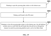
- FIG. 19 is a flow chart of another kind of method for using the pill cutter. As shown in FIG. 19 , the method for using the pill cutter includes the following steps:
- the pill deblister operation and the pill-cutting operation are unified, and can be accomplished by one closing action, contact opportunities between the user and the pill are largely reduced.
- FIGS. 20 - 24 are schematic views of the steps of another kind of method for using the pill cutter.
- the pressing plate 2 is rotated to open relative to the bottom case 1 .
- the pill board 7 is put in the pill cutter, and the position of the pill cutter 7 is adjusted, so that the pill 71 to be removed (deblistered) is positioned between the pill deblister column 26 of the pressing plate 2 and the pill deblister hole 14 of the bottom case 1 .
- the pressing plate 2 is rotated for a single pressing, to close the pressing plate 2 relative to the bottom case 1 .
- the pill deblister column 26 firstly cooperates with the pill deblister hole 14 , to press the pill 71 out of the pill board 7 .
- the pill 71 passes through the pill deblister hole 14 and falls into the channel 16 .
- the pill 71 slides from a slope of the channel towards the positioning platform 13 at a lower position (a lower position along the gravity direction) under the function of gravity, the pill 71 is cut by the blade 4 on the fallen pressing plate 2 , the pill 72 which has been cut stays on the positioning platform 13 .
- the pill 71 is put on the positioning platform 13 by the user's hand. Then the pill 71 is cut by the blade 4 during a second time rotating and pressing. That is, during the first time rotating and pressing, only the pill deblister column 26 and the pill deblister hole 14 have effective functions, the blade 4 has no actual function. During the second time rotating and pressing, the blade 4 and the positioning platform 13 cooperate to cut the pill 71 , the pill deblister column 26 and the pill deblister hole 14 have no actual functions. But the present disclosure is not limited to this.
- the pill cutter can be inclined manually by the user, to help the pill to slide towards the positioning platform 13 along the channel 16 , but the present disclosure is not limited to this.
- the blade can be shielded automatically when the pill cutter is opened for putting the pill in, the blade is prevented from being exposed and scratching the user, and the safety of using the pill cutter is largely enhanced.
- the pill deblister operation and the pill-cutting operation are unified, and can be accomplished by one closing action, contact opportunities between the user and the pill are largely reduced.
Landscapes
- Health & Medical Sciences (AREA)
- Life Sciences & Earth Sciences (AREA)
- Animal Behavior & Ethology (AREA)
- General Health & Medical Sciences (AREA)
- Public Health (AREA)
- Veterinary Medicine (AREA)
- Medical Preparation Storing Or Oral Administration Devices (AREA)
- Treatment Of Fiber Materials (AREA)
Abstract
Description
Claims (16)
Applications Claiming Priority (2)
| Application Number | Priority Date | Filing Date | Title |
|---|---|---|---|
| CN202010265297.XA CN113491633B (en) | 2020-04-07 | 2020-04-07 | Medicine cutter and use method thereof |
| CN202010265297.X | 2020-04-07 |
Publications (2)
| Publication Number | Publication Date |
|---|---|
| US20210308013A1 US20210308013A1 (en) | 2021-10-07 |
| US11672736B2 true US11672736B2 (en) | 2023-06-13 |
Family
ID=77921093
Family Applications (1)
| Application Number | Title | Priority Date | Filing Date |
|---|---|---|---|
| US17/167,748 Active 2041-08-08 US11672736B2 (en) | 2020-04-07 | 2021-02-04 | Pill cutter and method for using thereof |
Country Status (2)
| Country | Link |
|---|---|
| US (1) | US11672736B2 (en) |
| CN (1) | CN113491633B (en) |
Cited By (1)
| Publication number | Priority date | Publication date | Assignee | Title |
|---|---|---|---|---|
| USD1007704S1 (en) * | 2023-08-03 | 2023-12-12 | Rong Wu | Pill cutter |
Families Citing this family (4)
| Publication number | Priority date | Publication date | Assignee | Title |
|---|---|---|---|---|
| USD1074172S1 (en) * | 2009-09-22 | 2025-05-13 | Shabbir Azam | Pill holder |
| US12138230B2 (en) * | 2022-04-22 | 2024-11-12 | E-Link Plastic & Metal Industrial Co., Ltd. | Pill cutter |
| USD1006429S1 (en) * | 2023-09-07 | 2023-12-05 | Guangzhou Shuangmu Technology Co., Ltd. | Pill case |
| USD1006430S1 (en) * | 2023-09-08 | 2023-12-05 | Guangzhou Yueyuegui Intelligent Technology Co., Ltd | Pill case |
Citations (17)
| Publication number | Priority date | Publication date | Assignee | Title |
|---|---|---|---|---|
| US3517871A (en) * | 1968-11-15 | 1970-06-30 | James P Gaffney | Tablet cutter |
| US20030005800A1 (en) * | 2001-07-03 | 2003-01-09 | Robert Czarnek | Automatic tablet-cutting device and cutting method |
| US6557945B1 (en) * | 2001-11-02 | 2003-05-06 | Pharmadesign, Inc. | Tablet cutter |
| US20050067452A1 (en) | 2003-09-25 | 2005-03-31 | Daniel Darst | Pill box and splitter with blade guard |
| US7093363B1 (en) | 2005-07-12 | 2006-08-22 | Kuo Jack C | Foldable razor assembly |
| US20090019705A1 (en) * | 2007-07-17 | 2009-01-22 | Helen Of Troy Limited | Egg slicer |
| US20120060374A1 (en) | 2010-09-13 | 2012-03-15 | Noble Terrance O | Tablet cutter with slide guide and methods |
| CN203227036U (en) | 2013-05-21 | 2013-10-09 | 哈尔滨圣泰药业有限公司 | Tablet coating stripping device |
| CN103610594A (en) | 2013-12-06 | 2014-03-05 | 深圳国际旅行卫生保健中心 | Medicine dispenser |
| CN103610593A (en) | 2013-12-03 | 2014-03-05 | 福州斯狄渢电热水器有限公司 | Drug splitting device |
| US20170128324A1 (en) | 2014-04-24 | 2017-05-11 | Questa Corporation | Multi-size pill splitter and methods |
| US20170273868A1 (en) | 2016-03-22 | 2017-09-28 | Yu-Chien WANG | Device for cutting medicine tablet |
| CN206745627U (en) | 2016-12-23 | 2017-12-15 | 上海市嘉定区马陆镇社区卫生服务中心 | Push type cuts medicine device |
| CN206822853U (en) | 2016-12-30 | 2018-01-02 | 温州市人民医院 | Band cuts the medicine box of medicine device |
| US20180333333A1 (en) * | 2016-12-07 | 2018-11-22 | E-Link Plastic & Metal Industrial Co., Ltd. | Safe tablet cutting device |
| US20190060173A1 (en) | 2017-08-31 | 2019-02-28 | Puthalath Koroth Raghuprasad | 30 day pill cutting device |
| CN209337132U (en) | 2018-12-13 | 2019-09-03 | 黑龙江农垦职业学院 | Stripping medicine device for Western medicine drug packages shell |
-
2020
- 2020-04-07 CN CN202010265297.XA patent/CN113491633B/en active Active
-
2021
- 2021-02-04 US US17/167,748 patent/US11672736B2/en active Active
Patent Citations (17)
| Publication number | Priority date | Publication date | Assignee | Title |
|---|---|---|---|---|
| US3517871A (en) * | 1968-11-15 | 1970-06-30 | James P Gaffney | Tablet cutter |
| US20030005800A1 (en) * | 2001-07-03 | 2003-01-09 | Robert Czarnek | Automatic tablet-cutting device and cutting method |
| US6557945B1 (en) * | 2001-11-02 | 2003-05-06 | Pharmadesign, Inc. | Tablet cutter |
| US20050067452A1 (en) | 2003-09-25 | 2005-03-31 | Daniel Darst | Pill box and splitter with blade guard |
| US7093363B1 (en) | 2005-07-12 | 2006-08-22 | Kuo Jack C | Foldable razor assembly |
| US20090019705A1 (en) * | 2007-07-17 | 2009-01-22 | Helen Of Troy Limited | Egg slicer |
| US20120060374A1 (en) | 2010-09-13 | 2012-03-15 | Noble Terrance O | Tablet cutter with slide guide and methods |
| CN203227036U (en) | 2013-05-21 | 2013-10-09 | 哈尔滨圣泰药业有限公司 | Tablet coating stripping device |
| CN103610593A (en) | 2013-12-03 | 2014-03-05 | 福州斯狄渢电热水器有限公司 | Drug splitting device |
| CN103610594A (en) | 2013-12-06 | 2014-03-05 | 深圳国际旅行卫生保健中心 | Medicine dispenser |
| US20170128324A1 (en) | 2014-04-24 | 2017-05-11 | Questa Corporation | Multi-size pill splitter and methods |
| US20170273868A1 (en) | 2016-03-22 | 2017-09-28 | Yu-Chien WANG | Device for cutting medicine tablet |
| US20180333333A1 (en) * | 2016-12-07 | 2018-11-22 | E-Link Plastic & Metal Industrial Co., Ltd. | Safe tablet cutting device |
| CN206745627U (en) | 2016-12-23 | 2017-12-15 | 上海市嘉定区马陆镇社区卫生服务中心 | Push type cuts medicine device |
| CN206822853U (en) | 2016-12-30 | 2018-01-02 | 温州市人民医院 | Band cuts the medicine box of medicine device |
| US20190060173A1 (en) | 2017-08-31 | 2019-02-28 | Puthalath Koroth Raghuprasad | 30 day pill cutting device |
| CN209337132U (en) | 2018-12-13 | 2019-09-03 | 黑龙江农垦职业学院 | Stripping medicine device for Western medicine drug packages shell |
Non-Patent Citations (2)
| Title |
|---|
| 1st Office Action dated May 7, 2022 of Chinese Application No. 202010265297.X. |
| 2nd Office Action dated Sep. 26, 2022 of Chinese Application No. 202010265297.X. |
Cited By (1)
| Publication number | Priority date | Publication date | Assignee | Title |
|---|---|---|---|---|
| USD1007704S1 (en) * | 2023-08-03 | 2023-12-12 | Rong Wu | Pill cutter |
Also Published As
| Publication number | Publication date |
|---|---|
| US20210308013A1 (en) | 2021-10-07 |
| CN113491633A (en) | 2021-10-12 |
| CN113491633B (en) | 2023-01-03 |
Similar Documents
| Publication | Publication Date | Title |
|---|---|---|
| US20210308013A1 (en) | Pill cutter and method for using thereof | |
| US10850897B2 (en) | Container with child-resistant lid release and microdosing | |
| US10010484B2 (en) | Multi-size pill splitter and methods | |
| US6601746B2 (en) | Tablet splitting device | |
| US5118021A (en) | Pill splitter | |
| US20230346646A1 (en) | Delivery device for drug pellets | |
| EP0211595B1 (en) | Devices for administering medicaments to patients | |
| US10123943B2 (en) | Portable device for cutting a capsule | |
| CN221738790U (en) | A medical multifunctional plastic medicine bottle | |
| TWM602040U (en) | Medicine cutter and cutting part thereof | |
| CN215082361U (en) | Integral type divides medicine storage device | |
| CN221831186U (en) | Tablet cutting and grinding machine | |
| CN219127462U (en) | A pill dispenser for equally divided tablets | |
| TWI671173B (en) | Improved structure of the cutting device | |
| TW202322781A (en) | Granule drugs cutting device capable of effectively positioning table to be cut and preventing arbitrary slip or deflection during cutting | |
| CN113997334B (en) | Medicine cutting machine | |
| JP2002102312A (en) | Tablet / capsule removal equipment | |
| Russell | Research on Old Drugs: Expand Indications | |
| Baskararajan et al. | Orbital foreign body-case reports | |
| DE10218997A1 (en) | Device for singly removing tablets, pills and the like from blister packaging units comprises a housing, a lid and a core unit whose size and shape corresponds to the size and shape of blister elements | |
| CN117864609A (en) | A quantitative reminder storage box for convenient use of multiple ophthalmic eye drops | |
| TWM574549U (en) | Improved medicine cutting structure | |
| Chin | Sugarcoating male contraception |
Legal Events
| Date | Code | Title | Description |
|---|---|---|---|
| AS | Assignment |
Owner name: SONG YANG, CHINA Free format text: ASSIGNMENT OF ASSIGNORS INTEREST;ASSIGNORS:TIAN, ZEXU;TIAN, HONGLIANG;YANG, SONG;REEL/FRAME:055152/0171 Effective date: 20201228 |
|
| FEPP | Fee payment procedure |
Free format text: ENTITY STATUS SET TO UNDISCOUNTED (ORIGINAL EVENT CODE: BIG.); ENTITY STATUS OF PATENT OWNER: SMALL ENTITY |
|
| FEPP | Fee payment procedure |
Free format text: ENTITY STATUS SET TO SMALL (ORIGINAL EVENT CODE: SMAL); ENTITY STATUS OF PATENT OWNER: SMALL ENTITY |
|
| STPP | Information on status: patent application and granting procedure in general |
Free format text: DOCKETED NEW CASE - READY FOR EXAMINATION |
|
| STPP | Information on status: patent application and granting procedure in general |
Free format text: NON FINAL ACTION MAILED |
|
| STPP | Information on status: patent application and granting procedure in general |
Free format text: RESPONSE TO NON-FINAL OFFICE ACTION ENTERED AND FORWARDED TO EXAMINER |
|
| STPP | Information on status: patent application and granting procedure in general |
Free format text: NON FINAL ACTION MAILED |
|
| STCF | Information on status: patent grant |
Free format text: PATENTED CASE |
|
| AS | Assignment |
Owner name: MAXPERT TECHNOLOGIES INC., CANADA Free format text: ASSIGNMENT OF ASSIGNORS INTEREST;ASSIGNOR:YANG, SONG;REEL/FRAME:075082/0545 Effective date: 20260612 |