US1167231A - Automatic releasing device. - Google Patents
Automatic releasing device. Download PDFInfo
- Publication number
- US1167231A US1167231A US87254614A US1914872546A US1167231A US 1167231 A US1167231 A US 1167231A US 87254614 A US87254614 A US 87254614A US 1914872546 A US1914872546 A US 1914872546A US 1167231 A US1167231 A US 1167231A
- Authority
- US
- United States
- Prior art keywords
- lever
- arm
- releasing device
- shoulder
- disposed
- Prior art date
- Legal status (The legal status is an assumption and is not a legal conclusion. Google has not performed a legal analysis and makes no representation as to the accuracy of the status listed.)
- Expired - Lifetime
Links
- 238000010276 construction Methods 0.000 description 1
Images
Classifications
-
- G—PHYSICS
- G04—HOROLOGY
- G04F—TIME-INTERVAL MEASURING
- G04F3/00—Apparatus which can be set and started to measure-off predetermined or adjustably-fixed time intervals with driving mechanisms, e.g. dosimeters with clockwork
- G04F3/02—Apparatus which can be set and started to measure-off predetermined or adjustably-fixed time intervals with driving mechanisms, e.g. dosimeters with clockwork with mechanical driving mechanisms
- G04F3/027—Apparatus which can be set and started to measure-off predetermined or adjustably-fixed time intervals with driving mechanisms, e.g. dosimeters with clockwork with mechanical driving mechanisms using electrical contacts, e.g. for actuating electro-acoustic device
-
- Y—GENERAL TAGGING OF NEW TECHNOLOGICAL DEVELOPMENTS; GENERAL TAGGING OF CROSS-SECTIONAL TECHNOLOGIES SPANNING OVER SEVERAL SECTIONS OF THE IPC; TECHNICAL SUBJECTS COVERED BY FORMER USPC CROSS-REFERENCE ART COLLECTIONS [XRACs] AND DIGESTS
- Y10—TECHNICAL SUBJECTS COVERED BY FORMER USPC
- Y10T—TECHNICAL SUBJECTS COVERED BY FORMER US CLASSIFICATION
- Y10T74/00—Machine element or mechanism
- Y10T74/11—Tripping mechanism
- Y10T74/114—Retarded
- Y10T74/116—Clock train
Definitions
- My invention has for its object to provide an automatic releasing device which may be used to open or close feeding apparatus, the drafts on furnaces and stoves and for similar purposes.
- the second lever When the second lever is operated by means provided, it frees the shoulder from the first lever to permit the first lever to move to free the weight therefrom, thereby permitting the fall of the weight to operate means connected with the feeding apparatus or the furnace drafts.
- a casing 5 is provided in which there is disposed a frame 6 having stops 7 and 8 which serve to limit the movement of the arm 9 of the lever 10 fulcrumed at 11 to the frame 6.
- a weight 12 is disposed through an opening 13 in the bottom of the casing 5 and is provided with a loop 14 which is normally disposed over the other arm 15 of the lever 10.
- the end 16 of the arm 9 of the lever 10 is normally engaged by a shoulder 17 on a vertically disposed lever 18 which is fulcrumed at 19 to the frame 6.
- An arm 20 is articulated to the lever 18 at 21, this arm 20 having a slot 22 in which a guide pin 23 is disposed, the
- the devlce is constructed with a lever on Patented an. 4, 191a.
- the outer terminal 24 ofthe arm 20. is disposed for engagement by the cam 25, onthe cam member 26, this cam member 26, as best shown in'Fig. 2 of the drawings, being mounted onthe sleeve :27 of a clock which carries'the' hour hand 28, the cam member 26 having frictional engagement with the said sleeve 27 so that while-it may be rotated relatively to the said sleeve 27 the cam member 26. under normal conditions will be rotated by the sleeve 27.
- portion 29 of the cam will normally engage the terminal 2 1 of the arm 20, to push the lever18-i'nto positionwhere its shoulder 17 will engage the terminal, 16 of the arm 9 of the lever 10; but with the rota tion ofthe cam member 26, the cam at the point 30, will engage the terminal 24: of the arm 20 and with the further rotation of the cam member 26, the terminal 2a of the arm 20 will move to the recess 31, under the influence of the lever 18 and the spring 32 which connects the lever 18 with the frame 6 at the point 33.
- the arm 20 is positioned at the hour nine on the clock dial 34: and the recess 31 is disposed opposite the hour 9 on the face of the cam member '26. It will, therefore, be understood that the cam member 26 may be rotated relatively to the sleeve-27 until the hour at which the device is to operate. is positioned at the hour hand 28 on the clock.
- a lever a Weight normally supported on one arm of the lever, a second lever disposed substantially at right angles to the first mentioned lever and having a shoulder engaging the other arm of the first mentioned lever, a spring for moving the second mentioned lever to free its shoulder from the first mentioned lever, an arm pivoted to the second mentioned lever for moving the latter against the resiliency of the spring, the arm being disposed in a horizontal plane substantially parallel
- guide means for the arm a rotatably mounted member, and a cam engaging the arm and having frictional engagement with the rotatably mounted member.
- cam normally engaging the arm and having marks thereon to assist in setting the cam relatively to the hands.
Landscapes
- Physics & Mathematics (AREA)
- General Physics & Mathematics (AREA)
- Transmission Devices (AREA)
Description
Patented Jan.4, 1916.
INVENTOR- AmhurJTizl'ey ATTORNEYS WITNESSES g 'w coLuMBu PLANOURAPH COHWASHIPIIGTON, D. c.
ARTHUR J. TIZLEY, OF NEW YORK, N. Y.
AUTOMATIC RELEASING DEVICE.
York, have invented a new and Improved Automatic Releasing Device,.i'of which the following is a full, clear, and exact description.-
My invention has for its object to provide an automatic releasing device which may be used to open or close feeding apparatus, the drafts on furnaces and stoves and for similar purposes.
one arm of which a weight is disposed, the other arm being engaged by a shoulder on a second lever, positionedat an angle to the first lever. When the second lever is operated by means provided, it frees the shoulder from the first lever to permit the first lever to move to free the weight therefrom, thereby permitting the fall of the weight to operate means connected with the feeding apparatus or the furnace drafts.
Additional objects of the invention will appear in the following specification in which the preferred form of my invention is disclosed.
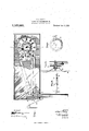
In the drawings similar reference characters refer to similar parts in all the views in which- Figure 1 is a view showing my invention in elevation, parts being broken away to better illustrate the construction; Fig. 2 is an enlarged sectional view on the line 22 of Fig. 1; Fig. 3 is a sectional view on the line 33 of Fig. 1; and Fig. 4. is an enlarged.
view showing the rear cam member.
By referring to the drawings it will be seen that a casing 5 is provided in which there is disposed a frame 6 having stops 7 and 8 which serve to limit the movement of the arm 9 of the lever 10 fulcrumed at 11 to the frame 6. A weight 12 is disposed through an opening 13 in the bottom of the casing 5 and is provided with a loop 14 which is normally disposed over the other arm 15 of the lever 10. The end 16 of the arm 9 of the lever 10 is normally engaged by a shoulder 17 on a vertically disposed lever 18 which is fulcrumed at 19 to the frame 6. An arm 20 is articulated to the lever 18 at 21, this arm 20 having a slot 22 in which a guide pin 23 is disposed, the
Specification of Letters Eatent.
Application filed November 1?, i914. Serial No. grams.
The devlce is constructed with a lever on Patented an. 4, 191a.
guide pin 23 being supported bythe frame'6. The outer terminal 24 ofthe arm 20. is disposed for engagement by the cam 25, onthe cam member 26, this cam member 26, as best shown in'Fig. 2 of the drawings, being mounted onthe sleeve :27 of a clock which carries'the' hour hand 28, the cam member 26 having frictional engagement with the said sleeve 27 so that while-it may be rotated relatively to the said sleeve 27 the cam member 26. under normal conditions will be rotated by the sleeve 27. It will be understood that theportion 29 of the cam will normally engage the terminal 2 1 of the arm 20, to push the lever18-i'nto positionwhere its shoulder 17 will engage the terminal, 16 of the arm 9 of the lever 10; but with the rota tion ofthe cam member 26, the cam at the point 30, will engage the terminal 24: of the arm 20 and with the further rotation of the cam member 26, the terminal 2a of the arm 20 will move to the recess 31, under the influence of the lever 18 and the spring 32 which connects the lever 18 with the frame 6 at the point 33. This will free the lever 18 at its shoulder 17 from the'terminal 16 V of the drawings, so that it may be set relatively to the hands of the clock, The arm 20 is positioned at the hour nine on the clock dial 34: and the recess 31 is disposed opposite the hour 9 on the face of the cam member '26. It will, therefore, be understood that the cam member 26 may be rotated relatively to the sleeve-27 until the hour at which the device is to operate. is positioned at the hour hand 28 on the clock. When this has been done, the cam member 26 will rotate with the sleeve 27 and when the hour hand 28 of the clock reaches the hour on the clock dial 34 at which the device is to operate, the recess 31 will be positioned ,to permit the terminal 2 1 of the arm 20 to claim as new and desire to secure by Letters Patent:
1. In a device of the class described, a lever, a Weight normally supported on one arm of the lever, a second lever disposed substantially at right angles to the first mentioned lever and having a shoulder engaging the other arm of the first mentioned lever, a spring for moving the second mentioned lever to free its shoulder from the first mentioned lever, an arm pivoted to the second mentioned lever for moving the latter against the resiliency of the spring, the arm being disposed in a horizontal plane substantially parallel With the first mentioned lever, guide means for the arm, a rotatably mounted member, and a cam engaging the arm and having frictional engagement with the rotatably mounted member.
2. In a device of the class described, a horizontal lever, a Weight normally supported on an arm of the lever, a second lever Copies of this patent may be obtained for five cents each,
having a shoulder engaging the other arm of the first mentioned lever, a spring for moving the second mentioned lever to free its shoulder from the first mentioned lever having frictional engagement therewith, the
cam normally engaging the arm and having marks thereon to assist in setting the cam relatively to the hands.
In testimony whereof I have signed my name to this specification in the presence of the tWo subscribing Witnesses.
ARTHUR J. TIZLEY.
Vfitnesses: V
HENRY C. liARRrs, G120. KNoonn.
by addressing the Commissioner-of Patents.
Washington, D. C.
Priority Applications (1)
| Application Number | Priority Date | Filing Date | Title |
|---|---|---|---|
| US87254614A US1167231A (en) | 1914-11-17 | 1914-11-17 | Automatic releasing device. |
Applications Claiming Priority (1)
| Application Number | Priority Date | Filing Date | Title |
|---|---|---|---|
| US87254614A US1167231A (en) | 1914-11-17 | 1914-11-17 | Automatic releasing device. |
Publications (1)
| Publication Number | Publication Date |
|---|---|
| US1167231A true US1167231A (en) | 1916-01-04 |
Family
ID=3235250
Family Applications (1)
| Application Number | Title | Priority Date | Filing Date |
|---|---|---|---|
| US87254614A Expired - Lifetime US1167231A (en) | 1914-11-17 | 1914-11-17 | Automatic releasing device. |
Country Status (1)
| Country | Link |
|---|---|
| US (1) | US1167231A (en) |
Cited By (1)
| Publication number | Priority date | Publication date | Assignee | Title |
|---|---|---|---|---|
| US2711217A (en) * | 1954-04-26 | 1955-06-21 | Lee S Gaty | Automatic feed box |
-
1914
- 1914-11-17 US US87254614A patent/US1167231A/en not_active Expired - Lifetime
Cited By (1)
| Publication number | Priority date | Publication date | Assignee | Title |
|---|---|---|---|---|
| US2711217A (en) * | 1954-04-26 | 1955-06-21 | Lee S Gaty | Automatic feed box |
Similar Documents
| Publication | Publication Date | Title |
|---|---|---|
| US761756A (en) | Photographic shutter. | |
| US1167231A (en) | Automatic releasing device. | |
| US708364A (en) | Repeating clock. | |
| US912516A (en) | Photographic timing apparatus. | |
| US1151773A (en) | Door operating and closing mechanism. | |
| US765992A (en) | Pedometer. | |
| US577573A (en) | Timepiece-dial | |
| US346399A (en) | Clock mechanism for operating gas-cocks | |
| US237159A (en) | Albeet bonzon | |
| US1095259A (en) | Escapement-adjustment for clocks. | |
| US785863A (en) | Electric time-switch. | |
| US818077A (en) | Door holding and releasing device. | |
| US248935A (en) | Striking mechanism of repeating-clocks | |
| US983661A (en) | Alarm-regulator. | |
| US1221679A (en) | Burglar-trap. | |
| US2306992A (en) | Lamp standard | |
| US527698A (en) | Automatic fire-lighter | |
| US458459A (en) | Nicholay jensen | |
| US762748A (en) | Time gas-lighter. | |
| US1100936A (en) | Gas-lighter. | |
| US663852A (en) | Time lighting device. | |
| US62531A (en) | John decker | |
| US637237A (en) | Globe. | |
| US1327391A (en) | Watch-setting lever | |
| US1175625A (en) | Pocket match-scratcher. |