US1166638A - Blow-off valve for steam-boilers. - Google Patents
Blow-off valve for steam-boilers. Download PDFInfo
- Publication number
- US1166638A US1166638A US2856615A US2856615A US1166638A US 1166638 A US1166638 A US 1166638A US 2856615 A US2856615 A US 2856615A US 2856615 A US2856615 A US 2856615A US 1166638 A US1166638 A US 1166638A
- Authority
- US
- United States
- Prior art keywords
- valve
- stem
- recess
- shield
- yoke
- Prior art date
- Legal status (The legal status is an assumption and is not a legal conclusion. Google has not performed a legal analysis and makes no representation as to the accuracy of the status listed.)
- Expired - Lifetime
Links
Images

Classifications
-
- F—MECHANICAL ENGINEERING; LIGHTING; HEATING; WEAPONS; BLASTING
- F16—ENGINEERING ELEMENTS AND UNITS; GENERAL MEASURES FOR PRODUCING AND MAINTAINING EFFECTIVE FUNCTIONING OF MACHINES OR INSTALLATIONS; THERMAL INSULATION IN GENERAL
- F16K—VALVES; TAPS; COCKS; ACTUATING-FLOATS; DEVICES FOR VENTING OR AERATING
- F16K1/00—Lift valves or globe valves, i.e. cut-off apparatus with closure members having at least a component of their opening and closing motion perpendicular to the closing faces
- F16K1/32—Details
- F16K1/34—Cutting-off parts, e.g. valve members, seats
- F16K1/36—Valve members
Description
l. F. SCHILLER.
Low-oFF v-ALvE FOR STE-AM BOILERs. APPLICATIDNv FILED MAY l1, i915.
1,166,638, v Patented Jan.4, 1916.
2 SHEETS-SHEET 1. fir-5.1.,
v I ,--52 "i B2.
v a Y All dagegen 'fcaizize,
COLUMBIA PLANOGRAPH co.. WASHINGTON, D. c.
J. F. SCHILLER. l BLOW-OFF VALVE Fon STEAM BOILERS.
nu 1 9 .1 4, fn a Tu d LL D e M ,D1 s.. M n A M D E .IL H N 0 n A c u .P DI A Q 8 o0. 6, .n0 6 1 Il 1 2 lSHEETS-SHEET 2.
@WH-ummm JOSEPH r. scHILLnn, or rnirapnrirnia, rnNNsYLvaitiA.
:BLOW-err VALVE ron smaila-Bonnes.
v Specification of Lettersilatrent. 311.44, 1916.
Application filed May 17, 1915. Seralil'o. 28,566.l
To all whom it mag/ concern Be it ,known that I, JOSEPH F. SCHILLER, a citizen of the United States, residing at Philadelphia, in the county of Philadelphia and State of Pennsylvania, have invented certain new and useful Improvements in Blow-Off Valves for Steam-Boilers, of which the following is a specification. n
My invention relates to improvements in blow olf valves for steam boilers,and more particularly to a blowofl' valve for steam boilers in which the piston valve is balanced in opening and closing so as to permit the valve to be readily manipulated without exerting undue force.
A further object is to provide a blow off valve in which the packing around the stem, as well as around the piston valve, is maintained tight by the pressure of steam.
A further object is to provide a valve lof the character stated in which the packing ring around the stem can be manually tightened by drawing the valve past its full open position.
A further object is to provide animproved combination kof valve and which are engaged by rings movable on the stem and having springs holding-the rings in normal position, and preventing movement of the packing on the stem, but I would have it understood that I the springsV to hold the packing but utilize the steam pressure to maintain the packing tight.
A further object is to provide a blow olf valve of the character stated which is steam tight, which is comparatively simple in construction, which can be manufactured and sold at a reasonably low price, which is strong and'durable in use, comes the defects of valves heretofore known.
Vith these and other objects in view, the
A invention consists in certain novel features i position and in a Y Fig. 2 1s a hereinafter described and pointed out in the claims.
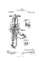
In'the accompanying drawings: Figure 1 Y is a view in longitudinal section illustrating my improvements showing the'valve'in open bodyof the angle type. fragmentary view partly in elevation and partly in section illustrating the yoke and the unionV connecting the same to the valve body.
Fig. 3 is a view in transverse,V section on the line 3-3 of ystem packing dov not rely upon and which over- Abody andlsecurely I v Fig. 2. `Fig. 4 1s a view Vin longitudinal section illustrating the'valve in closed Vposition showing the same in connection withV a body .ofthe st'raightway` type. Fig. 5 is a perspective View of the shield 21, 4and Fig. 6 is a perspective view of the shield 9 showing the latter in an Vinverted position. n f
1 `represents the body of the valve having an inlet 2. and an outlet- 3, and this body may be either of the angular type shown in Fig. 1, or Fig. 4', and as these types of bodyare common 1n the trade, I make no claim thereto,
inserted and removed, but this difference may be very slight as indicated.
A packing ring 8 is located around the stem 5 against the end of valve 4, and is engaged by a shield. 9 movable on the stem and held against the packing by a coiled spring 10 located around the valve stem between the nuts 7 and the shield 9. The shield9 on its lower face is flat from its outer edge in` wardly as shown at 11, and then tapers or inclines downwardly forming. an annular beveled extension 12 .which engages behind the packing ring 8. and tends to force the packing ring outwardly against the'walls of the casing.. The end of piston valve lis flat for a distanceV inwardly as shown at 13, and then bevels or inclines upwardly as shown at 111, and the packing ring 8 is of a shape to fit the surfaces of shield 9 and the piston end,
juncture.l
The upper end of the body 1 is externally screw-threaded as shown at 15,` and a union 16 is screwed y,onto the threaded end of the l the ring between 4 the lla-t surfaces, thereby insure a tight clamps a yoke17` .posi-.
of the straightway type shown vin .70 but illustrate both forms to show that my 5 which extends above the upper body, and is screw-threaded tion on the end oi the body. r1`he valve stem 5 projects through an opening 18 in the lower portion of the yoke, and this lower portion of the yoke is recessed as shown at 19 to accommodate a packing ring 2O and a shield 21. A coiled spring 22 which bears at its upper end against shield 21 is housedA within a recess 23 in the upper end et body 1, and at its lower end bears against the bottom wall 24 of said recess. The shield 21 adjacent its central opening has a fiat surface 25, and the outer portion of said shield flares or inclines outwardly from said flat portion 25 to the outer edge of the shield constituting a beveled bearing surface 26 to engage the packing ring 20. The upper end oi recess 19 in yoke 17 is made with a flat bearing surface 27 adjacent the opening 18, and then said end wall flares downwardly toward the outer wall of the recess forming a beveled surface 28. rilhe packing ring 20 is shaped to it the several beveled and flat surfaces above described on the .shield 21, and the lyoke 17, so that when pressure is had upon the shield 21, it tends to force the packing ring tightly around the valve stem and also tends to compress the ring, so that the stem is maintained steam and water tight.
A passage 29 is formed in the valve body 1, connecting the inlet 2 with the upper portion of the body 1, so that the shield 21 as well as the shield 9 are always maintained in communication with the direct pressure of steam and water, so that the pressure of steam upon the shields operates to maintain the packing rings tight.
The upper end of the stem 5 is hollow and internally screw-threaded as shown at 30 to receive the screw-threaded lower end 31 of the valve adjusting rod 32. The rod 32 is supported in the upper end oi.' the yoke 17, and is provided with a hand wheel 38 to turn the same.
A dog 34 is secured by a pin 85 to the upper end of valve stem 5, and is-provided with a key 36 which moves in a longitudinal slot 37 in one member of the yoke to hold the valve and stem against rotary movement,
but permit longitudinal movement as desired.
By reference to Figs. 1 and 4, it will be noted that in both positions of the valve, the shields 9 and 21 receive the direct pressure, and hence the packing rings 8 and 20 are maintained tight because of the fact that they receive a uniform 'pressure of steam and the life of the valve without renewal of packing is greatly increased. Furthermore,
it will be noted that the valve is an easy opening and closing valve because the passage 29 acts as a by-pass to allow the water to tlow to the upper end or" the body and equalize pressure.
While my invention is of course not limited to the particular material from which the rings 8 and 2O are made, l preferably form them oi metal or ot' a suitable composition which is best adapted for the use, but l may also make them of liber or any other material.
Various slight changes might be made in the general form and arrangement ot' parts described without departing from my invention, and hence do not limit myself to the precise details set forth, but consider myself at liberty to make such changes and alterations as fairly fall within the spirit and scope of the appended claims.
Having thus described my invention, what l claim as new and desire to secure by Letters Patent is:
1. A blow oli valve for steam boilers, coinprising a body having a cylindrical bore, said body having an inlet and an outlet, a piston valve fitting the bore and having a stem projecting above the body, a yoke secured to the upper end oit the body and haring a recess in its lower end, said body having a recess in its upper end communicating with the recess in the yoke, and having a passage connecting said recess in the body with the inlet of the body, a packing ring around the stem in the recess of the yoke, a shield around the stem in the recess ot the yoke, a packing ring around the stem against the end of the valve, a shield around the stem against the last-mentioned packing ring, and elastic means holding both of said shields against their packing rings, substantially as described.
2. A blou7 oli'l valve for steam boilers, comprising a body having a cylindrical bore, said body having an inlet and an outlet, a piston valve fitting the bore and having a stem projecting above the body, a yoke secured to the upper end of the body and having a recess in its lower end, said body having' a recess in its upper end communicating with the recess in the yoke, and having a passage connecting said recess in the body with the inlet of the body, a packing ring around the stem in the recess of the yoke, a shield around the stem in the recess of the yoke, a packing ring around the stem against the end of the valve, a shield around the stem against the lastmentioned packing ring, elastic means holding the last-mentioned shield against its packing ring, and a spring located in the recess in the upper end of the body and exerting pressure on the rst -mentioned shield, substantially as described.
8. Ablow oli'z valve for steam boilers, com-` prising a body having a cylindrical bore,
I a shield around the stein against the Vlastsaid body having an inlet andan outlet, a piston valve fitting the bore and having a stem projecting above the body, a yoke secured to the upper end of the body and having a recess in its lower end, said body having a recess in its upper end communicating with the recess in the yoke, and having a passage connecting said recess in the body with the inlet of thel body, a packing ring around the stem in the recess of the yoke, a shield around the stem in the recess of the yoke, a packing ring around the stem against the end of the valve, a shield around the stem against the last-mentioned packing ring, and respective coiled springs exerting constant pressure on said shields, substantially`as described.
4. A blow ofin valve Jfor steam boilers, comprising a body having a cylindrical bore, said body having an vinlet and an outlet, a piston valve fitting the bore and having a stem proj ecting above the body, a yoke secured to the upper end of the body and having a recess in its lower end, said body having a recess in its upper end communicating with the recess in the yoke, and having a passage connecting said recess in the body with the inlet of the body, a packing ring around the stein in the recess of the yoke, a shield around the stem in the recess of the yoke, a packing ring around the stem against the end of the valve,
mentioned packing ring, respective coiled springs exerting constant pressure on said shields, said shields and packing rings having beveled and fiat faces, the upper shield recessed portion oi' the body, a yoke secured on the upper end of the body and having anV opening therein, avpiston valve iittiiig the bore of the body and having a stem projecting through the opening in the yoke, packing rings around the stem adjacent the piston and the opening in the yoke respectively,
shields around the stern against the packing rings, 'portionl of the stein, a coiled spring around nuts screwed onto an intermediate the stein between the nuts and the piston packing ring shield, a second spring located in the recess in the body bearing at one end against the end wall of said recess and at its other end against the stem packing ring shield, means for preventing rotary movement of the valve, and means for moving the valve longitudinally, substantially as described. v
In testimony whereof Iliavev signed my name to this specification in the presence of two subscribing witnesses. y
' JOSEPH 1T. SCHILLER. Witnesses: f
CHAs. E. Poms, 4MARIE JACKSON.
Copies of this patent may be obtained for five cents each, by addressing the Commissioner of Patents,
Washington, D. C. Y
against the bore of
Priority Applications (1)
| Application Number | Priority Date | Filing Date | Title |
|---|---|---|---|
| US2856615A US1166638A (en) | 1915-05-17 | 1915-05-17 | Blow-off valve for steam-boilers. |
Applications Claiming Priority (1)
| Application Number | Priority Date | Filing Date | Title |
|---|---|---|---|
| US2856615A US1166638A (en) | 1915-05-17 | 1915-05-17 | Blow-off valve for steam-boilers. |
Publications (1)
| Publication Number | Publication Date |
|---|---|
| US1166638A true US1166638A (en) | 1916-01-04 |
Family
ID=3234659
Family Applications (1)
| Application Number | Title | Priority Date | Filing Date |
|---|---|---|---|
| US2856615A Expired - Lifetime US1166638A (en) | 1915-05-17 | 1915-05-17 | Blow-off valve for steam-boilers. |
Country Status (1)
| Country | Link |
|---|---|
| US (1) | US1166638A (en) |
Cited By (1)
| Publication number | Priority date | Publication date | Assignee | Title |
|---|---|---|---|---|
| US3211419A (en) * | 1960-02-12 | 1965-10-12 | Istag A G | Piston valve with spring pressed head |
-
1915
- 1915-05-17 US US2856615A patent/US1166638A/en not_active Expired - Lifetime
Cited By (1)
| Publication number | Priority date | Publication date | Assignee | Title |
|---|---|---|---|---|
| US3211419A (en) * | 1960-02-12 | 1965-10-12 | Istag A G | Piston valve with spring pressed head |
Similar Documents
| Publication | Publication Date | Title |
|---|---|---|
| US1166638A (en) | Blow-off valve for steam-boilers. | |
| US645696A (en) | Blow-off valve. | |
| US967460A (en) | Three-way valve. | |
| US117704A (en) | Improvement in valves | |
| US298865A (en) | John s | |
| US976908A (en) | Valve. | |
| US1020449A (en) | Valve. | |
| US727195A (en) | Gage-cock. | |
| US553390A (en) | Check-valve | |
| US58503A (en) | Improvement in steam-engine globe-valves | |
| US51349A (en) | Improvement in cocks | |
| US269111A (en) | Globe-valve | |
| US127468A (en) | Improvement in gauge-cocks | |
| US968559A (en) | Check-valve. | |
| US791634A (en) | Shot-cup for bottle-washing machines. | |
| US991095A (en) | Globe-valve. | |
| US774732A (en) | Valve for high-pressure pumps. | |
| US678014A (en) | Removable valve-seat. | |
| US690490A (en) | Renewable-seat valve. | |
| US58039A (en) | Improvement in steam-engine valves | |
| US821120A (en) | Throttle-valve. | |
| US1205660A (en) | Valve. | |
| US913644A (en) | Blow-off valve. | |
| US653300A (en) | Renewable-seat valve. | |
| US77517A (en) | Albert moore and a |