US1166562A - Molding-machine. - Google Patents
Molding-machine. Download PDFInfo
- Publication number
- US1166562A US1166562A US2877015A US2877015A US1166562A US 1166562 A US1166562 A US 1166562A US 2877015 A US2877015 A US 2877015A US 2877015 A US2877015 A US 2877015A US 1166562 A US1166562 A US 1166562A
- Authority
- US
- United States
- Prior art keywords
- mold
- bell
- core
- pipe
- tamping
- Prior art date
- Legal status (The legal status is an assumption and is not a legal conclusion. Google has not performed a legal analysis and makes no representation as to the accuracy of the status listed.)
- Expired - Lifetime
Links
- 239000000463 material Substances 0.000 description 27
- 238000000465 moulding Methods 0.000 description 15
- 238000007493 shaping process Methods 0.000 description 13
- 241000239290 Araneae Species 0.000 description 12
- 230000000694 effects Effects 0.000 description 6
- 230000006835 compression Effects 0.000 description 3
- 238000007906 compression Methods 0.000 description 3
- 230000033001 locomotion Effects 0.000 description 2
- 239000002184 metal Substances 0.000 description 2
- 230000002787 reinforcement Effects 0.000 description 2
- 244000278455 Morus laevigata Species 0.000 description 1
- 235000013382 Morus laevigata Nutrition 0.000 description 1
- 208000027418 Wounds and injury Diseases 0.000 description 1
- 230000015572 biosynthetic process Effects 0.000 description 1
- 239000004568 cement Substances 0.000 description 1
- 238000010276 construction Methods 0.000 description 1
- 230000006378 damage Effects 0.000 description 1
- 238000006073 displacement reaction Methods 0.000 description 1
- 208000014674 injury Diseases 0.000 description 1
- 230000003014 reinforcing effect Effects 0.000 description 1
Images


Classifications
-
- B—PERFORMING OPERATIONS; TRANSPORTING
- B29—WORKING OF PLASTICS; WORKING OF SUBSTANCES IN A PLASTIC STATE IN GENERAL
- B29C—SHAPING OR JOINING OF PLASTICS; SHAPING OF MATERIAL IN A PLASTIC STATE, NOT OTHERWISE PROVIDED FOR; AFTER-TREATMENT OF THE SHAPED PRODUCTS, e.g. REPAIRING
- B29C33/00—Moulds or cores; Details thereof or accessories therefor
-
- B—PERFORMING OPERATIONS; TRANSPORTING
- B29—WORKING OF PLASTICS; WORKING OF SUBSTANCES IN A PLASTIC STATE IN GENERAL
- B29L—INDEXING SCHEME ASSOCIATED WITH SUBCLASS B29C, RELATING TO PARTICULAR ARTICLES
- B29L2031/00—Other particular articles
- B29L2031/712—Containers; Packaging elements or accessories, Packages
-
- Y—GENERAL TAGGING OF NEW TECHNOLOGICAL DEVELOPMENTS; GENERAL TAGGING OF CROSS-SECTIONAL TECHNOLOGIES SPANNING OVER SEVERAL SECTIONS OF THE IPC; TECHNICAL SUBJECTS COVERED BY FORMER USPC CROSS-REFERENCE ART COLLECTIONS [XRACs] AND DIGESTS
- Y10—TECHNICAL SUBJECTS COVERED BY FORMER USPC
- Y10S—TECHNICAL SUBJECTS COVERED BY FORMER USPC CROSS-REFERENCE ART COLLECTIONS [XRACs] AND DIGESTS
- Y10S425/00—Plastic article or earthenware shaping or treating: apparatus
- Y10S425/218—Pipe machine: socket forming apparatus
Definitions
- F ig.v 4 is anenla-rged fragmentary section of a.bellring.1and-ad, lJacent-portions ofapipemoldfand its core;
- Fig. 5 is a section showing a reinforce, in position in the pipe mold.
- a ⁇ Referring to the drawings, 1 indicates la primary mold here shown as a pipe mold provided with a vflaring bell end l supported on the apertured bed 3 yof atrucktraveling on rails 4; said mold beingprovided'with anfauXiliary mold .section 5 detachably s up.
- LAbell ring 7 which iny this form consti-7 ⁇ tutes a shaping and tamping end ⁇ for thev mold adapted to fit closely through .the aper-- tured bed 3, is carried by aplaten 8 sup*Vl ported by pinand slotconnections 9 onthe shortarms of aseries .ofbell-,crank' levers 1.0,
- llevers 15 being provided with weights '171 for' yieldingly maintaining them iny their normal upper position against a limiting. stop 18.
- the bell-crank leversl() are connected tov secured on a sprocket driven power-actuated ,shaft 21, for oscillating said bell-crank 851 levers 10 to reciprocate the platen 8 and the f f shaping end 7 carried byf the latter.
- a sprocket driven power-actuated ,shaft 21 for oscillating said bell-crank 851 levers 10 to reciprocate the platen 8 and the f f shaping end 7 carried byf the latter.
- Ob viously, vany other. well known power-actuated or'manually-operated means could be a employed-in placey of the eccentrics Q'O-for oscillatingsaid bell crank leversv 10.
- a pipe core 22 provided with a conical upper end 35 is detachably secured to a head vertical square shaft 25 journaled at26 in a" lower frame 27; said shaftQ carrying a fast gear 28 in mesh with a pinion Q9 cna drive shaft 30. .A series of screw shafts 31;
- a loose gear 33 rotatably mountedl on the shaft 25.
- the gear. v33 meshes'with arloose pinion 34 on the kdrive shaft 30; 'said-loosezalq.
- the spiderr24 is providedwith4 @i pins' 36 adapted to engage the' weighted bellf crankleversl and swing the latter to lower# ⁇ the vertical rods 13 and the bell-crank levers 10 fulcrumed on said rods; thereby lowering the platen 8 to automatically withdraw the bell ring 7 from the mold 1 when said spiderl 24 has been low-ered to withdraw the pipe core from said mold.
- the screw shafts 30 are ro-tated by the gear 33 to lower the spider 24 and shift the pipe core 22 downwardly to position for extending through the bell ring 7 for closing the bottom of the mold; in this position of said core, the pins 36 on the spider are not loweredinto engagement with the bell-crank levers 15, and said levers 15 are maintained upwardly by their weights 17 to position the bell ring 7 within the pipe mold.
- a plunger 38 with a face adapted to shape that end of the object, here a pipe, which is opposite the end shaped by the tamping member or bell ring 7.
- this plunger' is hollow. This hollow is to accommodate the upper part of the core 22 which protrudes into it when the eli'ect of the plunger is complete.
- This plunger is actuated by hydraulic cylinder 39, or any other well known power device.
- InF ig. 5 I have indicated in outline, a mold in which reinforce has been placed prior to filling.
- the reinforce should be such as to resist lateral strain rather than longitudinal stresses, the reinforce extending to about the top of the primary mold.
- Ir show a wire 40 and supporting rods 41 for said wire.
- This rotation is to effect an even distribution of the material within the mold, and also to smooth the inner surface of the object, if a round object or an object with a round opening in it, is to be shaped.
- the plunger 38 which, as stated above, constitutes a forming end of the mold, is then thrust or forced downward by the hydraulic cylinder, and the material from the auxiliary mold section 5 is, by this movement, compacted so that the total length of the object molded does not exceed the length of the primary mold 1.
- the mold supporting carriage is then shifted along the track 4 for removing the completed mold, and a new mold similarly shifted into position for the formation of a pipe.
- the pipe and mold are allowed to stand until the concrete of the pipe has partly set, then the section 5 is lifted off and the two parts of the mold 1 removed.
- my invention provides an improved means for insuring a strong compression and uniform density of the plastic material throughout the pipe length, and is adapted to operate effectively on all characters of reinforcing pipes without danger of displacing or destroying the metal reinforcements.
- I claim 1 In a molding machine, the combination of a mold, an auxiliary mold section thereon, means for supplying material to one end of said mold section, a plunger, means for forcing said plunger' through said section for compressing the material in said mold, a reciprocating member extending within the opposite end of said mold, and means for reciprocating said member during the actuation of said plunger.
- a pipe mold provided with a Haring bell. end, a detachable auxiliary mold section thereon, means for supplying material to said mold and section, a plunger, means for forcing said plunger ythrough said section for compressing the material in said mold, a bell ring extending within the Haring end of said mold, and means for reciprocating said bell ring during the actuation of said plunger.
- a pipe molding machine the combination of a mold, a reciprocatingly mounted plpe core, Ymeans for inserting and withdrawing said core from said mold, means foi; ⁇ rotating said core in its several shifted positions,.a bell ring'slidably mounted on said core, means for shifting said bell ring into and out of said mold, and means for reciprocating said bell ring for tamping the material in said mold.
- a pipe molding machine the combination of a mold, a core, means for shifting said core into and out of said'mold, a bell ring slidably mounted on said core, weights for normally maintaining said bell ring within said mold, and means for withdrawing said bell ring from said mold.
- a pipe molding machine the combination of a mold, an apertured supporting bed therefor, a bell ring adapted to extend slidably through said apertured bed, a platen supporting said bell ring, a series of bellcrank levers reciprocatingly supporting said platen, means for oscillating said bell-crank levers for reciprocating said bell ring within i said mold, and means for engaging said weighted means for automatically withdrawing said bell ring from said mold.
- a pipe mold provided with a flaring bell end, a detachable auxiliary mold section thereon, means for supplying material to said mold and section, a plunger, means for forcing said plunger through said section, a core, means for rotating said core, a bell ring, and means for reciprocating said bell ring and rotating said core during the action of the plunger.
- a laterally separable mold in combination, a laterally separable mold, removable ends for said mold, means for moving one of said ends forward into said mold to shape and compress material in said mold, means for moving the second end forward to close the end of said mold, and means for giving said second end a reciprocating tamping action while it is in its forward position.
- a laterally separable mold in combination, a laterally separable mold, removable ends for said mold, means for moving one of said ends forward into said mold to shape and compress material in said mold, ⁇ means for moving ⁇ the second end forward to close'lv the end of said mold, andimeans for giving said secondend a reciprocating tamping aca mold, removable ends for said mold, means foi' moving oneof said ends forward to shape and compress material 1n said mold, means for moving the second end forward to shape the second end of the object, meansfor moving forward a. core through said second end, ⁇ and means for withdrawing y said second end and core lto permit the lateral removal of the mold and object.
- a primary mold shaping ends for said mold, one of said ends being adapted to tamp and the lother to compress with steady pressure, material in the mold, and means for'actuating said tamping and compressing ends simultaneously, whereby material in said mold is subjected to directly opposed compressing and tamping effects.
- a primary mold shaping ends for said mold, one of said ends being adapted to tamp and the other to compress with steady pressure, material in the mold, means for actuating said tamping and compressing ends simultaneously whereby material in said mold is subjected to directly opposed compressing and tamping eects, and an auxiliary mold adapted to be joined to one end of said primary mold and to hold a quantity of material sufficient to compensate for the compacting effect of the compressing and tamping actions.
- a molding machine in combination, a mold, an apertured supporting bed therefor, a track on which said bed and mold may be moved into and out of position, a shaping end adapted to be pushed through the apertured bed, a support for said shaping end, bell crank levers supporting said end support, vertical rods supporting said bell crank levers, weighted bell cranks supporting said rods, a core adapted to pass through said shaping end into the mold, a spider carrying said core, means for moving said spider forward and back, means for reciprocating said end supporting levers, and
- a. primary mold Y provided with movable ends, a detachable auxiliary mold for one of said ends, means for supplying material to and through said auxiliary mold, a shaping plunger, means for forcing said plunger through said section for compacting the material in said auxiliary mold into the primary mold, a second shaping end for said primary mold, and means for recipro cating said second end to elfect a tamping connection during the compressing move ment of the compressing end.
- a molding machine in combination, a primar)7 mold, a core therefor, a compressing end for on-e end of said mold, a tamping end for the other end of Said mold, a core for said primarymold, an opening in each of said ends through Which said core may pass, and means for giving to one end a compressing action and to the other end a tamping action simultaneously.
Landscapes
- Engineering & Computer Science (AREA)
- Mechanical Engineering (AREA)
- Manufacturing Of Tubular Articles Or Embedded Moulded Articles (AREA)
- Moulds For Moulding Plastics Or The Like (AREA)
Description
A. C. TUNISON.
MQLDING MACH|NE. APPLICATION FILED IULY, IQIS. RENEWED MAY I7, i915.
1,166,562. Patented' Jan. 4, V1916.
a SHEETS-sain l.
COLUMBIA PLANOURAPH cc., WASHINGTON. D. c.
A. C. TUNISON. I MOLDING M'Ac'HlNL. APPLICATIONTIPED JULY?, 1913. RENEWED MAY U. 1915. l
Patented @11.4, 1916.
a SHEETS-SHEET 2 COLUMBIA PLANouRAPM C0., WASHINGTON, D c.
A. C. TUNISONl MoLmNG MACHINE.
APPLICATION FILED IULY?, I9I3. RENEWED MAY I7, 1915.
y1, 166,562. ylhtented J mi. 4,. 1916.
i ii T STS: 4" y i ARTHUR C. Tunisien, orsALTLAIincIT-Y, UTAH, EAssiernoa To ATLAs CQNCRETE PIPE f MACHINERY COMPANY, or sALT LAKE CITY, UTAH, A coRroRATIoN or UTAII.
MoLLING-i/IACHINE.
speciaation f Lettersyratent.'
i ratenteaaana, 191e.
Application lecl July 7, 1913, Serial No. 777,797. Renewed May 17, 1915. Serial No. 28,770.
To @Hicham it mayy camera A Be itknown thatl, ARTHUR C. TUNisoN,
a citizen ofthe United States,ir esiding at Salt Lake City, in the county of Salt Lake and State of Utah, have inventedl certain new and useful mprovementsiinMoldingr Machinesyand I do hereby declare the following to be a full, clear, and exact descrip,-
tion of theiinvention, such as will enable PPS?f Anobject of my invention is to` provide van,
improved machine for forming pipes o r other objects of` concrete or other plastic material, which will operate automatically to insure a greater compression and rmore uniform density of the material throughout the length of the object Vmoldedthan hasv been possible in previous 'machinesl #In vmolding certain kinds of concrete,particularly cement or hydraulic concrete, itis desirable to haveany compressing and ltamping effect, directedas much as possible along one.V
line. 4In my present invention I ihave de-v vised means for eifecting both a compressing anda tamping effectalong one line .in opposed directions, so that the material is both compressed and tamped between the two means, while subjected to comparatively little lateral displacement.f Y
AA further object of my invention tisfto provide a compactv and strong machine for 1 forming objects oficoncrete or other plastic J:
' i 23 -swiveled on a spider'24 and provided withl ..a square openingfor'slidably receivingv a material, which will have a maximum'caf pacity and operate effectively for forming reinforced or other pipes without danger `of. 'I
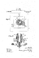
injury to the metal reinforcements In theaccompanying drawings forming a: part of this application, in which similar` reference ysymbols indicate corresponding parts in the several-views: yFigurelis a detail side elevation illustrating oneembodiment of my inventioma pipe mold and-compressingv plunger1 being shown in axial section; Fig. Q'is an elevation at the right hand! of Fig. 1, vwith a pipe mold-and plunger" shown in section; Fig. 3 isa section on/the line 4'3 3 of Figp4; F ig.v 4 is anenla-rged fragmentary section of a.bellring.1and-ad, lJacent-portions ofapipemoldfand its core;
andk Fig. 5 is a section showing a reinforce, in position in the pipe mold. a `Referring to the drawings, 1 indicates la primary mold here shown as a pipe mold provided with a vflaring bell end l supported on the apertured bed 3 yof atrucktraveling on rails 4; said mold beingprovided'with anfauXiliary mold .section 5 detachably s up.
ported thereon'in` any suitable manner, as by4 lugs 6 engaging the outer periphery of 4 said mold 1 which is in three parts.
gether in pairsby links 11 ,pivotally connected to the radius rods 19 of eccentrics 20 The bell-crank leversl() are connected tov secured on a sprocket driven power-actuated ,shaft 21, for oscillating said bell-crank 851 levers 10 to reciprocate the platen 8 and the f f shaping end 7 carried byf the latter. Ob viously, vany other. well known power-actuated or'manually-operated means could be a employed-in placey of the eccentrics Q'O-for oscillatingsaid bell crank leversv 10.
A pipe core 22 provided with a conical upper end 35 is detachably secured to a head vertical square shaft 25 journaled at26 in a" lower frame 27; said shaftQ carrying a fast gear 28 in mesh with a pinion Q9 cna drive shaft 30. .A series of screw shafts 31;
are threaded through the spider 24, with.
theirV lower ends journaled inthe framel27 and provided withfpinionsBQ in mesh with.
a loose gear 33 rotatably mountedl on the shaft 25. The gear. v33 meshes'with arloose pinion 34 on the kdrive shaft 30; 'said-loosezalq.
pinion `34 being adapted-to `be locked to thef,`
drive shaft-30 by anyi'usual formfof shiftable clutch. The spiderr24 is providedwith4 @i pins' 36 adapted to engage the' weighted bellf crankleversl and swing the latter to lower#` the vertical rods 13 and the bell-crank levers 10 fulcrumed on said rods; thereby lowering the platen 8 to automatically withdraw the bell ring 7 from the mold 1 when said spiderl 24 has been low-ered to withdraw the pipe core from said mold.
In the operation of my invention, the screw shafts 30 are ro-tated by the gear 33 to lower the spider 24 and shift the pipe core 22 downwardly to position for extending through the bell ring 7 for closing the bottom of the mold; in this position of said core, the pins 36 on the spider are not loweredinto engagement with the bell-crank levers 15, and said levers 15 are maintained upwardly by their weights 17 to position the bell ring 7 within the pipe mold. I provide a plunger 38 with a face adapted to shape that end of the object, here a pipe, which is opposite the end shaped by the tamping member or bell ring 7. In the form of the invention here indicated, this plunger' is hollow. This hollow is to accommodate the upper part of the core 22 which protrudes into it when the eli'ect of the plunger is complete. This plunger is actuated by hydraulic cylinder 39, or any other well known power device.
InF ig. 5 I have indicated in outline, a mold in which reinforce has been placed prior to filling. In the case of a pipe the reinforce should be such as to resist lateral strain rather than longitudinal stresses, the reinforce extending to about the top of the primary mold. Ir show a wire 40 and supporting rods 41 for said wire. A measured batch of mixed concrete or other plastic material, the reinforce, if reinforce is to be used, having been first placed in position, is supplied to the mold from a hopper 37. rlhe core 22 is then thrust upward to its highest position within the mold 1 by the screw shafts 31; the square shaft 25 being driven by the gear 28. During such elevation the core 22 is rotated. The purpose of this rotation is to effect an even distribution of the material within the mold, and also to smooth the inner surface of the object, if a round object or an object with a round opening in it, is to be shaped. The plunger 38, which, as stated above, constitutes a forming end of the mold, is then thrust or forced downward by the hydraulic cylinder, and the material from the auxiliary mold section 5 is, by this movement, compacted so that the total length of the object molded does not exceed the length of the primary mold 1. IVhile the material is undergoing compression by the part 38, it is subjected to the tamping effect of the part 7 within the other end of the mold, thereby subjecting the plastic material to a strong pressure and a repeated tamping .action simultaneously in the respective ends of the mold, at the same time, of course, shaping it at both ends. After the plastic material has been thus strongly compacted within the mold 1, the screw shafts 31 are rotated by their gear 33 to further lower the spider 24 for withdrawing the core entirely from the mold. During such final lowering of the spider 24, the pins 36 thereon engage the bell-crank levers 15 and shift the vertical rods 13 downwardly to withdraw the bell ring 7 completely from the mold. The mold supporting carriage is then shifted along the track 4 for removing the completed mold, and a new mold similarly shifted into position for the formation of a pipe. The pipe and mold are allowed to stand until the concrete of the pipe has partly set, then the section 5 is lifted off and the two parts of the mold 1 removed.
From the above description, it will be clear that my invention provides an improved means for insuring a strong compression and uniform density of the plastic material throughout the pipe length, and is adapted to operate effectively on all characters of reinforcing pipes without danger of displacing or destroying the metal reinforcements.
I have illustrated and described preferred and satisfactory constructions, but changes could be made within the spirit and scope of my invention as disclosed in the statement of invention and the appended claims.
I claim 1. In a molding machine, the combination of a mold, an auxiliary mold section thereon, means for supplying material to one end of said mold section, a plunger, means for forcing said plunger' through said section for compressing the material in said mold, a reciprocating member extending within the opposite end of said mold, and means for reciprocating said member during the actuation of said plunger.
2. In a molding machine, the combination of a pipe mold provided with a Haring bell. end, a detachable auxiliary mold section thereon, means for supplying material to said mold and section, a plunger, means for forcing said plunger ythrough said section for compressing the material in said mold, a bell ring extending within the Haring end of said mold, and means for reciprocating said bell ring during the actuation of said plunger.
3. In a molding machine, the combination of a pipe mold, a detachable auxiliary mold section thereon, an apertured supporting bed therefor, a bell ring adapted to extend through said apertured bed, means for reciprocating said bell ring, a core, means for shifting said core through said bell ring into and out of said mold, means for rotating said core independently of such shifting thereof, and means for withdrawing said bell ring from the mold.
4. In a pipe molding machine, the combination of a mold, a reciprocatingly mounted plpe core, Ymeans for inserting and withdrawing said core from said mold, means foi;` rotating said core in its several shifted positions,.a bell ring'slidably mounted on said core, means for shifting said bell ring into and out of said mold, and means for reciprocating said bell ring for tamping the material in said mold.
5. In a. pipe molding machine, the combination of a mold, a core, means for shifting said core into and out of said'mold, a bell ring slidably mounted on said core, weights for normally maintaining said bell ring within said mold, and means for withdrawing said bell ring from said mold.
6. In a pipe molding machine, the combination of a mold, an apertured supporting bed therefor, a bell ring adapted to extend slidably through said apertured bed, a platen supporting said bell'ring, a series of bell-crank levers reciprocatingly supporting said platen, and weighted means for shifting said bell-crank levers for forcing said bell ring into said mold.
7. In a pipe molding machine, the combination of a mold, an apertured supporting bed therefor, a bell ring adapted to extend slidably through said apertured bed, a platen supporting said bell ring, a series of bellcrank levers reciprocatingly supporting said platen, means for oscillating said bell-crank levers for reciprocating said bell ring within i said mold, and means for engaging said weighted means for automatically withdrawing said bell ring from said mold.
8. In a molding machine, the combination of a pipe mold provided with a flaring bell end, a detachable auxiliary mold section thereon, means for supplying material to said mold and section, a plunger, means for forcing said plunger through said section, a core, means for rotating said core, a bell ring, and means for reciprocating said bell ring and rotating said core during the action of the plunger.
9. In a molding machine, in combination, a. laterally separable mold, removable ends for said mold, means for reciprocating one of said ends to produce a tamping effect, and means acting simultaneously therewith to move the other end forward with a compressing action.
10. In a molding machine, in combination, a laterally separable mold, removable ends for said mold, means for moving one of said ends forward into said mold to shape and compress material in said mold, means for moving the second end forward to close the end of said mold, and means for giving said second end a reciprocating tamping action while it is in its forward position.
11. In a. molding machine, in combination, a laterally separable mold, removable ends for said mold, means for moving one of said ends forward into said mold to shape and compress material in said mold, `means for moving `the second end forward to close'lv the end of said mold, andimeans for giving said secondend a reciprocating tamping aca mold, removable ends for said mold, means foi' moving oneof said ends forward to shape and compress material 1n said mold, means for moving the second end forward to shape the second end of the object, meansfor moving forward a. core through said second end,` and means for withdrawing y said second end and core lto permit the lateral removal of the mold and object.
13. In amolding machine, in combination, a primary mold, shaping ends for said mold, one of said ends being adapted to tamp and the lother to compress with steady pressure, material in the mold, and means for'actuating said tamping and compressing ends simultaneously, whereby material in said mold is subjected to directly opposed compressing and tamping effects.
14. In a molding machine, in combination, a primary mold, shaping ends for said mold, one of said ends being adapted to tamp and the other to compress with steady pressure, material in the mold, means for actuating said tamping and compressing ends simultaneously whereby material in said mold is subjected to directly opposed compressing and tamping eects, and an auxiliary mold adapted to be joined to one end of said primary mold and to hold a quantity of material sufficient to compensate for the compacting effect of the compressing and tamping actions. j
15. In a molding machine, in combination, a mold, an apertured supporting bed therefor, a track on which said bed and mold may be moved into and out of position, a shaping end adapted to be pushed through the apertured bed, a support for said shaping end, bell crank levers supporting said end support, vertical rods supporting said bell crank levers, weighted bell cranks supporting said rods, a core adapted to pass through said shaping end into the mold, a spider carrying said core, means for moving said spider forward and back, means for reciprocating said end supporting levers, and
means on said spider for engaging the rod supporting bell crank levers to lower the rods and withdraw the shaping end'upon ingl said bell crank levers, Weighted bell cranks supporting said rods, a core adapted to pass through said shaping end into the mold, a spider carrying said core, mea-ns for moving said spider forward and back, means for reciprocating said end supporting levers, and means on said spider for engaging the rod. supporting bell crank levers to lower the rods and Withdraw the shaping end upon the Withdrawal of the core.
17. In a molding machine, the combination of a. primary mold Yprovided with movable ends, a detachable auxiliary mold for one of said ends, means for supplying material to and through said auxiliary mold, a shaping plunger, means for forcing said plunger through said section for compacting the material in said auxiliary mold into the primary mold, a second shaping end for said primary mold, and means for recipro cating said second end to elfect a tamping connection during the compressing move ment of the compressing end.
18. In a molding machine, in combination, a primar)7 mold, a core therefor, a compressing end for on-e end of said mold, a tamping end for the other end of Said mold, a core for said primarymold, an opening in each of said ends through Which said core may pass, and means for giving to one end a compressing action and to the other end a tamping action simultaneously.
In testimony whereof, I aiiix my signature, in presence of two Witnesses.
ARTHUR C. TUNISON. lVitnesses:
CoNsTANoE JOHNSON,
G. W. Corn.
Copies of this patent may be obtained for tive cents each, by addressing the Commissioner of Patents.
Washington, D. C.
Priority Applications (1)
| Application Number | Priority Date | Filing Date | Title |
|---|---|---|---|
| US2877015A US1166562A (en) | 1915-05-17 | 1915-05-17 | Molding-machine. |
Applications Claiming Priority (1)
| Application Number | Priority Date | Filing Date | Title |
|---|---|---|---|
| US2877015A US1166562A (en) | 1915-05-17 | 1915-05-17 | Molding-machine. |
Publications (1)
| Publication Number | Publication Date |
|---|---|
| US1166562A true US1166562A (en) | 1916-01-04 |
Family
ID=3234583
Family Applications (1)
| Application Number | Title | Priority Date | Filing Date |
|---|---|---|---|
| US2877015A Expired - Lifetime US1166562A (en) | 1915-05-17 | 1915-05-17 | Molding-machine. |
Country Status (1)
| Country | Link |
|---|---|
| US (1) | US1166562A (en) |
Cited By (3)
| Publication number | Priority date | Publication date | Assignee | Title |
|---|---|---|---|---|
| US2448911A (en) * | 1945-09-01 | 1948-09-07 | Joseph Dixon Crucible Co | Stopper press die |
| US3119165A (en) * | 1961-03-20 | 1964-01-28 | Boise Cascade Corp | Automatic concrete pipe molding machine for belled pipe |
| US3454997A (en) * | 1965-11-30 | 1969-07-15 | Dickey Clay Mfg Co W S | Ceramic molding apparatus |
-
1915
- 1915-05-17 US US2877015A patent/US1166562A/en not_active Expired - Lifetime
Cited By (3)
| Publication number | Priority date | Publication date | Assignee | Title |
|---|---|---|---|---|
| US2448911A (en) * | 1945-09-01 | 1948-09-07 | Joseph Dixon Crucible Co | Stopper press die |
| US3119165A (en) * | 1961-03-20 | 1964-01-28 | Boise Cascade Corp | Automatic concrete pipe molding machine for belled pipe |
| US3454997A (en) * | 1965-11-30 | 1969-07-15 | Dickey Clay Mfg Co W S | Ceramic molding apparatus |
Similar Documents
| Publication | Publication Date | Title |
|---|---|---|
| US2888731A (en) | Molding press | |
| CN118386362B (en) | Forming device of building composite water permeable brick | |
| US2926411A (en) | Machine for making concrete pipes | |
| US1166562A (en) | Molding-machine. | |
| CN105600335A (en) | Steel reinforcement cage storage and conveying device used for tubular pile production line | |
| CN105563636B (en) | Steel reinforcement cage prestressing force drawing mechanism | |
| CN105666685B (en) | Pipe die tears fixed charge method end plate primary nut machine open | |
| US3822106A (en) | Apparatus for molding tubes of fiberous cement and orienting the fibers therein | |
| CN204000769U (en) | Full-automatic seepage channel cast-in-situ forming | |
| US3119165A (en) | Automatic concrete pipe molding machine for belled pipe | |
| CN103753845B (en) | Green bamboo extrusion molding machine and production method of green bamboo chopping board | |
| US3006053A (en) | Masonry block apparatus | |
| CN105690551A (en) | Vibration extrusion rapid forming device for artificial flood prevention reserved bricks | |
| US2015001A (en) | Machine for the manufacture of pipes or the lining thereof with cementitious materials | |
| US951740A (en) | Tile-making machine. | |
| US2603850A (en) | Method and apparatus for molding concrete products | |
| US450583A (en) | Machine for making sewer-pipe | |
| US1418859A (en) | Concrete-pipe machine | |
| US392069A (en) | Machine for making conduits | |
| US405185A (en) | sherman | |
| CN206924987U (en) | A kind of round plastic part screening plant for being conveniently replaceable screen cloth | |
| US1330760A (en) | Concrete-pipe machine | |
| USRE746E (en) | Improvement in brick-machines | |
| US1904094A (en) | Method and apparatus for molding concrete pipe | |
| US1267189A (en) | Molding-machine. |