US1166446A - Cultivator. - Google Patents
Cultivator. Download PDFInfo
- Publication number
- US1166446A US1166446A US4332015A US4332015A US1166446A US 1166446 A US1166446 A US 1166446A US 4332015 A US4332015 A US 4332015A US 4332015 A US4332015 A US 4332015A US 1166446 A US1166446 A US 1166446A
- Authority
- US
- United States
- Prior art keywords
- rollers
- shafts
- laterally
- adjusted
- curved
- Prior art date
- Legal status (The legal status is an assumption and is not a legal conclusion. Google has not performed a legal analysis and makes no representation as to the accuracy of the status listed.)
- Expired - Lifetime
Links
- 241001131696 Eurystomus Species 0.000 description 16
- 239000002689 soil Substances 0.000 description 3
- 230000004075 alteration Effects 0.000 description 1
- 238000005452 bending Methods 0.000 description 1
- 238000010276 construction Methods 0.000 description 1
Images

Classifications
-
- A—HUMAN NECESSITIES
- A01—AGRICULTURE; FORESTRY; ANIMAL HUSBANDRY; HUNTING; TRAPPING; FISHING
- A01B—SOIL WORKING IN AGRICULTURE OR FORESTRY; PARTS, DETAILS, OR ACCESSORIES OF AGRICULTURAL MACHINES OR IMPLEMENTS, IN GENERAL
- A01B33/00—Tilling implements with rotary driven tools, e.g. in combination with fertiliser distributors or seeders, with grubbing chains, with sloping axles, with driven discs
- A01B33/02—Tilling implements with rotary driven tools, e.g. in combination with fertiliser distributors or seeders, with grubbing chains, with sloping axles, with driven discs with tools on horizontal shaft transverse to direction of travel
- A01B33/021—Tilling implements with rotary driven tools, e.g. in combination with fertiliser distributors or seeders, with grubbing chains, with sloping axles, with driven discs with tools on horizontal shaft transverse to direction of travel with rigid tools
Definitions
- This 1nvent1on relates to the art of farmlng implements, and particularly to an improved cultivator, and an object ofthe in-- vention is to provide a frame having a partial circular guide, to which the cultivatlng rollers are connected by improved means, so
- rollers may be adjusted on angles toward the rear and laterally, or may be adjusted to assume positions alined with each otlher, or upon angles forwardlyandlater- In practical fields the details of construction may necessitate alterations, falling within the scope of What is claimed.
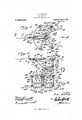
- Figure 1 is a planview
- FIG. 2 is a longitudinal sectional view on line 22 of Fig. 1.
- Fig. 3 is a rear view.
- Fig. 4 is a transverse'sectional View on line 4-4 ofFig. 1.
- Fig. 5 is a bottom plan view.
- 1 designates a tongue or pole, to which is secured as at 3 the rearwardly and laterally extending handles 3 terminating in the grips proper 4.
- a curved rod 7 Secured to the tongue 1 by the shank 5 of the T-shaped bolt 6 is a curved rod 7, the free ends of the part 8 of v'hich are secured at 9 to-the handles 3.
- the rods may be adjusted in the outermost grooves of said plates, in order to hold the rods farther apart.
- the lateral arms 24. of the T-shaped bolt are bent slightly upwardly to limit the rod 16 in beeXtending brackets 26 are provided.
- These brackets consist of substantially parallel arms 27 the upper ends of which are connected, ii'itegrallyto the elongated plates 28. which are curved in cross section and curved longitudinally to correspond with and fit the parts 8 of the curved rod 7
- These plates 28- Downwardly outer ends of the shafts 32 and'33 are 7 mounted.
- the inner ends of-the shafts 32 and 33 have eyes 34, through which the lower ends of the downwardly extending arms 18 extend.
- the lower ends of the downwardly extending arms 18 have nuts 36 threaded thereto to support the eyed ends of the shafts 32 and 33.
- the eyes 37 of the brace rods 38 also receive the lower part of the arms 18.
- the forward ends of the brace rods 38 are connected at 39 to the curved rod 7, thereby preventing the arms 18 from bending, rearwardly.
- Mounted upon the shafts 32 and 33 are the cultivator rollers 40, which are provided with metallic sleeve, bushings 41, secured in place by the threaded nuts 42, threaded to the ends of said bushings.
- the nuts 42 are countersunken in the cultivating rollers, as shown in transverse sectional view. Interposed between the bearings of the brackets and the outer ends of the rollers are suitable washers 43, and
- the rollers are provided
- the v outer ends of the shafts '32 and 33 are se- 11o i 'with suitable cutting orcultivating blades 46, which, as shown, extend radially. W hen the cultivating rollers extend angularly to' the rear and laterally, the dirt or soil is thrown laterally from each side of the plants, which pass between the inner ends of the rollers. However, when the rollers extend angularly forwardly and laterally, by adjusting the brackets forwardly upon the curved parts 8 of the curved rods 7, the dirt or soil is thrown toward the plants.
- rollers When the rollers are adjusted, alined axially, the soil or dirt upon e ch side of the plants is merely agitated or broken. If desired, one roller may be adjusted angularly toward the rear and laterally, while the other roller may be adjusted angularly and forwardly.
- bars or plates are provided to prevent spreading or expansion of the gangrollers.
- a cultivator a frame, a substantially circular rod mounted on the frame, rods pivotally connected to the forward part of the frame and having rea-rwardly and downwardly extending parts, shafts pivoted upon the lower ends of said downwardly extending parts, brackets in which the outer ends of the shafts have bearings, cultivating roll ers mounted upon the shafts, said bracket having adjustable connections to the curved rod whereby the brackets may be adjusted, so that the shafts may be adjusted angu- Gopies of this patent may be obtained for la'rly toward the rear and laterally or angularly forwardly and laterally, said adjustable connections of the bracket comprising plates semi-circular in cross section and curved to correspond with and fit the curved rod, and staples and means to secure the curved plates to the curved rod'adjustably.
- a frame a substantially circular rod mounted on the frame, rods pivotally connected to the forward part of the frame and having rearwardly and clownwardly extending parts, shafts pivoted upon the lower ends of said downwardly extending parts, brackets in which the outer ends of the shafts have bearings, cultivating rollers mounted upon the shafts, said bracket having adjustable connections to the curved rod whereby the brackets may be adjusted, so that the shafts may be adjusted angular-1y toward the rear and laterally or angularly forwardly and laterally, said adjustable connections of the bracket comprising plates semi-circular in cross section and curved to correspond with and fit the curved rod, and staples and means to secure the curved plates to the curved rod adjustably, and means whereby the rearwardly extending rods of the frame may be adjusted laterally.
Landscapes
- Life Sciences & Earth Sciences (AREA)
- Engineering & Computer Science (AREA)
- Mechanical Engineering (AREA)
- Soil Sciences (AREA)
- Environmental Sciences (AREA)
- Soil Working Implements (AREA)
Description
'-F. A; DAVIS, s. CULT|VATOR.'
APPLICATION FILED AUG.2, 191s. 1 166 446. Patented Jan. 4, 1916.
2 SHEETS-SHEET I.
COLUMBIA PLANOGRAPH co.,wAsmNu'mN n c v F. A. DAVIS, Sn.
QU LTIVATOR. APPLICATION FILED AUGJ, l9l5.
1,166,446." Y Patentd Jan.4, 1916.
2 sums-swan 2.
FRANK A. DAVIS, SR.,'0F B oUnTsrowN, F onI-DA.
GULTIVATbRI Specification of Letters Patent.
Patented Jan. 4., 1916.
Application filed August 2,'1915. I Serial No. 43,320.
To all whom it may concern:
Be it known that I, FRANK A. DAvIS,-Sr., a citizen of the United States, residing at Blountstown, in the county of Calhoun and State-of Florida, have invented a new and useful Cultivator; and I do hereby declare the following to be a full, clear,and exact description 'of' the invention, such as will 7 enable others skilled in the art to which it appertainsto make and-use the same.
This 1nvent1on relates to the art of farmlng implements, and particularly to an improved cultivator, and an object ofthe in-- vention is to provide a frame having a partial circular guide, to which the cultivatlng rollers are connected by improved means, so
that the rollers may be adjusted on angles toward the rear and laterally, or may be adjusted to assume positions alined with each otlher, or upon angles forwardlyandlater- In practical fields the details of construction may necessitate alterations, falling within the scope of What is claimed.
The invention comprises further features and combination of parts, as hereinafter set forth, shown in the drawings and claimed.
In the drawings :Figure 1 is a planview,
showing the cultivating rollers adjusted-angularly toward the rear and laterally from each other, also illustrating therollers adjusted upon angles forwardly and laterally. Fig. 2 is a longitudinal sectional view on line 22 of Fig. 1. Fig. 3 is a rear view. Fig. 4 is a transverse'sectional View on line 4-4 ofFig. 1. Fig. 5 is a bottom plan view.
Referring more especially to the drawings, 1 designates a tongue or pole, to which is secured as at 3 the rearwardly and laterally extending handles 3 terminating in the grips proper 4. Secured to the tongue 1 by the shank 5 of the T-shaped bolt 6 is a curved rod 7, the free ends of the part 8 of v'hich are secured at 9 to-the handles 3.
Secured by the bolt 10 to the tongue lis a bar 11, the arms 12 of which extend angu- M larly forwardly from each other and have their end portions secured to the parts 8 of the curved rod 7, by means of the staples 13 having nuts 14. Pivotally connected to the tongue 1 by means of the bolt 15 are rearwardly extending rods 16, which are bent at 17 forming thedownwardly extending arms 18. WVhere the rods 16 are bent a pair of plates 20 is provided having grooves 21 upon their adjacent surfaces, to receive the rods 16 ingadjusted farther apart.
- to prevent: the same from spreading. The platesareclamped together by the screw 23.
However, the rods may be adjusted in the outermost grooves of said plates, in order to hold the rods farther apart. I The lateral arms 24. of the T-shaped bolt are bent slightly upwardly to limit the rod 16 in beeXtending brackets 26 are provided. These brackets consist of substantially parallel arms 27 the upper ends of which are connected, ii'itegrallyto the elongated plates 28. which are curved in cross section and curved longitudinally to correspond with and fit the parts 8 of the curved rod 7 These plates 28- Downwardly outer ends of the shafts 32 and'33 are 7 mounted. The inner ends of-the shafts 32 and 33 have eyes 34, through which the lower ends of the downwardly extending arms 18 extend. The lower ends of the downwardly extending arms 18 have nuts 36 threaded thereto to support the eyed ends of the shafts 32 and 33. The eyes 37 of the brace rods 38 also receive the lower part of the arms 18. The forward ends of the brace rods 38 are connected at 39 to the curved rod 7, thereby preventing the arms 18 from bending, rearwardly. Mounted upon the shafts 32 and 33 are the cultivator rollers 40, which are provided with metallic sleeve, bushings 41, secured in place by the threaded nuts 42, threaded to the ends of said bushings. The nuts 42 are countersunken in the cultivating rollers, as shown in transverse sectional view. Interposed between the bearings of the brackets and the outer ends of the rollers are suitable washers 43, and
interposed between the eyed ends 3-4 of the shafts 32 and 33 and the inner ends of the rollers are suitable washers 44, which extend partially into the rollers as shown.
cured in the bearings of the bracketsby virtue of the'nuts 45. The rollers are provided The v outer ends of the shafts '32 and 33 are se- 11o i 'with suitable cutting orcultivating blades 46, which, as shown, extend radially. W hen the cultivating rollers extend angularly to' the rear and laterally, the dirt or soil is thrown laterally from each side of the plants, which pass between the inner ends of the rollers. However, when the rollers extend angularly forwardly and laterally, by adjusting the brackets forwardly upon the curved parts 8 of the curved rods 7, the dirt or soil is thrown toward the plants. When the rollers are adjusted, alined axially, the soil or dirt upon e ch side of the plants is merely agitated or broken. If desired, one roller may be adjusted angularly toward the rear and laterally, while the other roller may be adjusted angularly and forwardly.
It is to be observed that additional gang cultivating rollers may be supplied, and
moreover, it is to be noted that bars or plates are provided to prevent spreading or expansion of the gangrollers.
The invention having been set forth, what is claimed as new and useful is 1. In a cultivator, a frame, a substantially circular rod mounted on the frame, rods pivotally connected to the forward part of the frame and having rea-rwardly and downwardly extending parts, shafts pivoted upon the lower ends of said downwardly extending parts, brackets in which the outer ends of the shafts have bearings, cultivating roll ers mounted upon the shafts, said bracket having adjustable connections to the curved rod whereby the brackets may be adjusted, so that the shafts may be adjusted angu- Gopies of this patent may be obtained for la'rly toward the rear and laterally or angularly forwardly and laterally, said adjustable connections of the bracket comprising plates semi-circular in cross section and curved to correspond with and fit the curved rod, and staples and means to secure the curved plates to the curved rod'adjustably. 2. In a cultivator, a frame,a substantially circular rod mounted on the frame, rods pivotally connected to the forward part of the frame and having rearwardly and clownwardly extending parts, shafts pivoted upon the lower ends of said downwardly extending parts, brackets in which the outer ends of the shafts have bearings, cultivating rollers mounted upon the shafts, said bracket having adjustable connections to the curved rod whereby the brackets may be adjusted, so that the shafts may be adjusted angular-1y toward the rear and laterally or angularly forwardly and laterally, said adjustable connections of the bracket comprising plates semi-circular in cross section and curved to correspond with and fit the curved rod, and staples and means to secure the curved plates to the curved rod adjustably, and means whereby the rearwardly extending rods of the frame may be adjusted laterally. In testimony whereof I have signed my name to this specification in the presence of two subscribing witnesses.
FRANK A. DAVIS, SR. Witnesses J. M. ATKINs, BERTHA JONES.
five cents each, by addressing the Commissioner of Patents,
Washington, D. 0.
Priority Applications (1)
| Application Number | Priority Date | Filing Date | Title |
|---|---|---|---|
| US4332015A US1166446A (en) | 1915-08-02 | 1915-08-02 | Cultivator. |
Applications Claiming Priority (1)
| Application Number | Priority Date | Filing Date | Title |
|---|---|---|---|
| US4332015A US1166446A (en) | 1915-08-02 | 1915-08-02 | Cultivator. |
Publications (1)
| Publication Number | Publication Date |
|---|---|
| US1166446A true US1166446A (en) | 1916-01-04 |
Family
ID=3234467
Family Applications (1)
| Application Number | Title | Priority Date | Filing Date |
|---|---|---|---|
| US4332015A Expired - Lifetime US1166446A (en) | 1915-08-02 | 1915-08-02 | Cultivator. |
Country Status (1)
| Country | Link |
|---|---|
| US (1) | US1166446A (en) |
Cited By (1)
| Publication number | Priority date | Publication date | Assignee | Title |
|---|---|---|---|---|
| US20110139470A1 (en) * | 2008-08-14 | 2011-06-16 | Aquagronomy Limited | Land Management |
-
1915
- 1915-08-02 US US4332015A patent/US1166446A/en not_active Expired - Lifetime
Cited By (1)
| Publication number | Priority date | Publication date | Assignee | Title |
|---|---|---|---|---|
| US20110139470A1 (en) * | 2008-08-14 | 2011-06-16 | Aquagronomy Limited | Land Management |
Similar Documents
| Publication | Publication Date | Title |
|---|---|---|
| US1166446A (en) | Cultivator. | |
| US4725A (en) | Improvement in cultivators | |
| US378089A (en) | Cultivator | |
| US1003365A (en) | Cultivator-fender. | |
| US1218054A (en) | Disk attachment for plows. | |
| US4171A (en) | Improvement in cultivators | |
| US156715A (en) | Improvement in combined hand rakes and rollers | |
| US416595A (en) | Field-marker | |
| US285318A (en) | Cultivator | |
| US579622A (en) | Harrow | |
| US340360A (en) | Geoege b | |
| US151104A (en) | Improvement in cork | |
| US1153952A (en) | Cultivator. | |
| US649944A (en) | Plow. | |
| US1013476A (en) | Cultivator. | |
| US281125A (en) | Cotton-chopper | |
| US394619A (en) | Cultivator | |
| US1002492A (en) | Land-roller. | |
| US1113382A (en) | Agricultural implement. | |
| US339788A (en) | Joel thomas ketchum | |
| US160129A (en) | Improvement in land-pulverizers | |
| US667483A (en) | Cultivator. | |
| US660095A (en) | Weeder. | |
| US329609A (en) | Eichaed s | |
| US93651A (en) | Improvement in cultivators |