US11663087B2 - Validating metering of a disaster recovery service used in clouds - Google Patents
Validating metering of a disaster recovery service used in clouds Download PDFInfo
- Publication number
- US11663087B2 US11663087B2 US17/248,944 US202117248944A US11663087B2 US 11663087 B2 US11663087 B2 US 11663087B2 US 202117248944 A US202117248944 A US 202117248944A US 11663087 B2 US11663087 B2 US 11663087B2
- Authority
- US
- United States
- Prior art keywords
- cloud
- drs
- configuration
- metering
- usage
- Prior art date
- Legal status (The legal status is an assumption and is not a legal conclusion. Google has not performed a legal analysis and makes no representation as to the accuracy of the status listed.)
- Active, expires
Links
Images


Classifications
-
- G—PHYSICS
- G06—COMPUTING OR CALCULATING; COUNTING
- G06F—ELECTRIC DIGITAL DATA PROCESSING
- G06F11/00—Error detection; Error correction; Monitoring
- G06F11/30—Monitoring
- G06F11/3003—Monitoring arrangements specially adapted to the computing system or computing system component being monitored
- G06F11/3006—Monitoring arrangements specially adapted to the computing system or computing system component being monitored where the computing system is distributed, e.g. networked systems, clusters, multiprocessor systems
-
- G—PHYSICS
- G06—COMPUTING OR CALCULATING; COUNTING
- G06F—ELECTRIC DIGITAL DATA PROCESSING
- G06F11/00—Error detection; Error correction; Monitoring
- G06F11/07—Responding to the occurrence of a fault, e.g. fault tolerance
- G06F11/14—Error detection or correction of the data by redundancy in operation
- G06F11/1402—Saving, restoring, recovering or retrying
- G06F11/1446—Point-in-time backing up or restoration of persistent data
- G06F11/1456—Hardware arrangements for backup
-
- G—PHYSICS
- G06—COMPUTING OR CALCULATING; COUNTING
- G06F—ELECTRIC DIGITAL DATA PROCESSING
- G06F11/00—Error detection; Error correction; Monitoring
- G06F11/07—Responding to the occurrence of a fault, e.g. fault tolerance
- G06F11/14—Error detection or correction of the data by redundancy in operation
- G06F11/1402—Saving, restoring, recovering or retrying
- G06F11/1446—Point-in-time backing up or restoration of persistent data
- G06F11/1448—Management of the data involved in backup or backup restore
-
- G—PHYSICS
- G06—COMPUTING OR CALCULATING; COUNTING
- G06F—ELECTRIC DIGITAL DATA PROCESSING
- G06F11/00—Error detection; Error correction; Monitoring
- G06F11/07—Responding to the occurrence of a fault, e.g. fault tolerance
- G06F11/16—Error detection or correction of the data by redundancy in hardware
- G06F11/20—Error detection or correction of the data by redundancy in hardware using active fault-masking, e.g. by switching out faulty elements or by switching in spare elements
- G06F11/202—Error detection or correction of the data by redundancy in hardware using active fault-masking, e.g. by switching out faulty elements or by switching in spare elements where processing functionality is redundant
- G06F11/2023—Failover techniques
-
- G—PHYSICS
- G06—COMPUTING OR CALCULATING; COUNTING
- G06F—ELECTRIC DIGITAL DATA PROCESSING
- G06F11/00—Error detection; Error correction; Monitoring
- G06F11/07—Responding to the occurrence of a fault, e.g. fault tolerance
- G06F11/16—Error detection or correction of the data by redundancy in hardware
- G06F11/20—Error detection or correction of the data by redundancy in hardware using active fault-masking, e.g. by switching out faulty elements or by switching in spare elements
- G06F11/2053—Error detection or correction of the data by redundancy in hardware using active fault-masking, e.g. by switching out faulty elements or by switching in spare elements where persistent mass storage functionality or persistent mass storage control functionality is redundant
- G06F11/2094—Redundant storage or storage space
-
- G—PHYSICS
- G06—COMPUTING OR CALCULATING; COUNTING
- G06F—ELECTRIC DIGITAL DATA PROCESSING
- G06F11/00—Error detection; Error correction; Monitoring
- G06F11/30—Monitoring
- G06F11/3051—Monitoring arrangements for monitoring the configuration of the computing system or of the computing system component, e.g. monitoring the presence of processing resources, peripherals, I/O links, software programs
-
- G—PHYSICS
- G06—COMPUTING OR CALCULATING; COUNTING
- G06F—ELECTRIC DIGITAL DATA PROCESSING
- G06F11/00—Error detection; Error correction; Monitoring
- G06F11/30—Monitoring
- G06F11/34—Recording or statistical evaluation of computer activity, e.g. of down time, of input/output operation ; Recording or statistical evaluation of user activity, e.g. usability assessment
- G06F11/3409—Recording or statistical evaluation of computer activity, e.g. of down time, of input/output operation ; Recording or statistical evaluation of user activity, e.g. usability assessment for performance assessment
- G06F11/3433—Recording or statistical evaluation of computer activity, e.g. of down time, of input/output operation ; Recording or statistical evaluation of user activity, e.g. usability assessment for performance assessment for load management
-
- G—PHYSICS
- G06—COMPUTING OR CALCULATING; COUNTING
- G06F—ELECTRIC DIGITAL DATA PROCESSING
- G06F9/00—Arrangements for program control, e.g. control units
- G06F9/06—Arrangements for program control, e.g. control units using stored programs, i.e. using an internal store of processing equipment to receive or retain programs
- G06F9/46—Multiprogramming arrangements
- G06F9/50—Allocation of resources, e.g. of the central processing unit [CPU]
- G06F9/5061—Partitioning or combining of resources
- G06F9/5072—Grid computing
-
- G—PHYSICS
- G06—COMPUTING OR CALCULATING; COUNTING
- G06F—ELECTRIC DIGITAL DATA PROCESSING
- G06F9/00—Arrangements for program control, e.g. control units
- G06F9/06—Arrangements for program control, e.g. control units using stored programs, i.e. using an internal store of processing equipment to receive or retain programs
- G06F9/46—Multiprogramming arrangements
- G06F9/50—Allocation of resources, e.g. of the central processing unit [CPU]
- G06F9/5061—Partitioning or combining of resources
- G06F9/5077—Logical partitioning of resources; Management or configuration of virtualized resources
-
- G—PHYSICS
- G06—COMPUTING OR CALCULATING; COUNTING
- G06F—ELECTRIC DIGITAL DATA PROCESSING
- G06F2201/00—Indexing scheme relating to error detection, to error correction, and to monitoring
- G06F2201/815—Virtual
-
- G—PHYSICS
- G06—COMPUTING OR CALCULATING; COUNTING
- G06F—ELECTRIC DIGITAL DATA PROCESSING
- G06F2201/00—Indexing scheme relating to error detection, to error correction, and to monitoring
- G06F2201/86—Event-based monitoring
-
- G—PHYSICS
- G06—COMPUTING OR CALCULATING; COUNTING
- G06F—ELECTRIC DIGITAL DATA PROCESSING
- G06F2209/00—Indexing scheme relating to G06F9/00
- G06F2209/50—Indexing scheme relating to G06F9/50
- G06F2209/508—Monitor
Definitions
- Cloud refers to a virtual infrastructure provided on a collection of processing systems, connectivity infrastructure, data storages, etc.
- the virtual infrastructure contains computing resources (e.g., virtual machines, operating systems) and storage resources (e.g., database servers, file systems).
- a customer/owner (also known as tenant) of a cloud may deploy desired user applications/data services on the resources provided as a part of their cloud(s), with the services capable of processing user requests received from end user systems.
- DR Disaster recovery
- databases storing pertinent data in a storage node may be backed up to a backup node and applications may also be made operative in the backup node upon occurrence of a disaster in the storage node.
- Disaster recovery is often provided as a service (such as Disaster-Recovery-as-a-Service or DRaaS) to one or more customers.
- DRaaS Disaster-Recovery-as-a-Service
- Each customer may be billed for usage of the service.
- Metering implies measurement of such usage for each customer for purposes such as billing and planning.
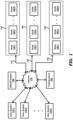
- FIG. 1 is a block diagram illustrating an example environment (computing system) in which several aspects of the present invention can be implemented.
- FIG. 2 A illustrates an example execution state within a node of a computing infrastructure.
- FIG. 2 B illustrates the manner in which clouds are hosted in computing infrastructures in one embodiment.
- FIG. 2 C illustrates the manner in which disaster recovery as a service is provided for multiple clouds/customers in one embodiment.
- FIG. 3 is a flow chart illustrating the manner in which validating metering of a disaster recovery service use in clouds is performed according to an aspect of the present disclosure.
- FIGS. 4 A- 4 D depicts user interfaces used for specifying the setup of a disaster recovery service in a cloud in one embodiment.
- FIG. 5 A depicts portions of category data specifying details of cloud resources (VMs) deployed in a cloud in one embodiment.
- VMs cloud resources
- FIG. 5 B depicts portions of policy data specifying details of disaster recovery policies setup in a cloud in one embodiment.
- FIG. 6 A illustrates the manner in which a test/second cloud is provisioned in a cloud infrastructure in one embodiment.
- FIG. 6 B illustrates the manner in which disaster recovery as a service is provided for test cloud in one embodiment.
- FIG. 7 is a timeline according to which the usage of a disaster recovery service in clouds is monitored in one embodiment.
- FIG. 8 A depicts portions of DRS usage information collected for a cloud in one embodiment.
- FIG. 8 B depicts the manner in which the DRS usage in a cloud is metered in one embodiment.
- FIG. 8 C depicts the manner in which the DRS usage in a cloud is billed in one embodiment.
- FIG. 8 D depicts a rate card according to which a customer/tenant is billed in one embodiment.
- FIG. 8 E depicts the manner in which the DRS usage in a cloud is billed in one embodiment.
- FIG. 9 A depicts portions of expected (metering) values representing expected usage of DRS in a cloud in one embodiment.
- FIG. 9 B depicts portions of DRS usage information collected for a cloud in one embodiment.
- FIG. 9 C depicts the manner in which expected values for a cloud is collated based on metering tiers in one embodiment.
- FIG. 9 D depicts the manner in which expected values are compared with measured values to validate metering of usage of DRS in a cloud in one embodiment.
- FIG. 9 E depicts the manner in which expected values are compared with measured values to validate billing of usage of DRS in a cloud in one embodiment.
- FIG. 10 is a block diagram illustrating the details of digital processing system in which various aspects of the present disclosure are operative by execution of appropriate executable modules.
- a system receives a request to validate metering of usage of a disaster recovery service (DRS) in a first cloud.
- the system collects from a metering service of the DRS, measured values representing the actual usage of the DRS in a second cloud and then compares the measured values with corresponding expected values representing expected usage of the DRS in the second cloud.
- the system sends a response to the request based on a result of the comparing.
- the request is received from a tenant (customer/owner) owning the first cloud.
- the DRS in the first cloud is setup to operate according to a first configuration specifying respective disaster recovery policies applicable to corresponding cloud resources in the first cloud.
- the DRS in the second cloud is also setup with the disaster recovery policies specified in the first configuration.
- the operation of the second cloud is similar to the first cloud (of the tenant) with respect to the usage of the DRS.
- the expected values correspond to prior values representing actual usage of the DRS in the first cloud in a past duration when the first cloud was operating based on the first configuration, the measured values corresponding to a first duration after receipt of the request, where the first duration equals the past duration.
- the first configuration is received along with the request.
- the system (noted above) then examines prior configurations setup for the DRS in the first cloud to identify a prior duration having a corresponding prior configuration matching the first configuration, as the past duration.
- the system provides a user interface to enable a user (customer/owner, administrator, etc.) to specify a first set of disaster recovery policies and submit the first set of disaster recovery policies as the first configuration of the first cloud.
- the request (noted above) and the first configuration are received in response to the user submission using the user interface.
- the system selects the past duration and identifies a prior configuration applicable to the selected past duration as the first configuration.
- the first cloud is provided based on a first cloud infrastructure. Accordingly, the system (noted above) in response to the request, prepares the second cloud in a second cloud infrastructure and configures the DRS in the second cloud according to the first configuration.
- the second cloud is separate and distinct from the first cloud (of the tenant) whose metering is sought to be validated.
- the first cloud contains a first primary site and a first secondary site, wherein the DRS in the first cloud is setup to backup cloud resources from the first primary site to the first secondary site according to the first configuration.
- the cloud resources are virtual machines provisioned as part of the first cloud.
- the first cloud is a hybrid cloud in which the first primary site is hosted in a on-premises infrastructure and the first secondary site is hosted in the first cloud infrastructure, while the second cloud is a multi-cloud cloud comprising a second primary site and a second secondary site, both being hosted in the second cloud infrastructure.
- the system performs collecting from a first time instance to a second time instance, where the first time instance is after receipt of the request.
- the system modifies the second cloud to also operate according to the second configuration and continues collecting the measured values from the modified second cloud in a duration between the third time instance and the second time instance.
- a customer/owner of a cloud is facilitated to validate metering of a disaster recovery service (DRS) used in his/her first cloud.
- the customer (using a user system) sends a request to validate metering of usage of a disaster recovery service (DRS) in the first cloud and receives a response to the request based on a result of a comparison of measured values representing the actual usage of the DRS in a second cloud and corresponding expected values representing expected usage of the DRS in the second cloud.
- DRS disaster recovery service
- FIG. 1 is a block diagram illustrating an example environment (computing system) in which several aspects of the present invention can be implemented.
- the block diagram is shown containing user systems 110 - 1 through 110 -Z (Z representing any natural number), Internet 115 , disaster recovery as a service (DRaaS) system 120 , testing server 150 , and computing infrastructures 130 , 160 and 180 .
- Computing infrastructure 130 in turn is shown containing nodes 140 - 1 through 140 -P (P representing any natural number).
- Computing infrastructure 160 in turn is shown containing nodes 170 - 1 through 170 -Q (Q representing any natural number).
- Computing infrastructure 180 in turn is shown containing nodes 190 - 1 through 190 -R (R representing any natural number).
- the user systems and nodes are collectively referred to by 110 , 140 , 170 and 190 respectively.
- FIG. 1 Merely for illustration, only representative number/type of systems is shown in FIG. 1 . Many environments often contain many more systems, both in number and type, depending on the purpose for which the environment is designed. Each block of FIG. 1 is described below in further detail.
- Each of computing infrastructures 130 , 160 and 180 is a collection of physical processing nodes ( 140 , 170 and 190 ), connectivity infrastructure, data storages, administration systems, etc., which are engineered to together provide a virtual computing infrastructure for various customers, with the scale of such virtual computing being specified often on demand.
- Computing infrastructure 130 / 160 / 180 may correspond to a public cloud infrastructure such as Amazon Web Services (AWS) Cloud available from Amazon.com, Inc., Google Cloud Platform (GCP) available from Google LLC, Azure cloud available from Microsoft, Inc., Xi cloud available from Nutanix etc.
- Computing infrastructure 130 / 160 / 180 may also correspond to one of the On-Premises (On-Prem) enterprise systems owned by corresponding customers.
- computing infrastructure 130 / 160 / 180 may correspond to a third-party data center provided by a cloud service provider.
- computing infrastructures 130 and 160 are On-Prem (on premises) enterprise systems owned by corresponding customers, while computing infrastructure 180 is a public cloud infrastructure such as AWS Cloud noted above. Accordingly, in the following description, the terms on-prem system 130 / 160 and cloud infrastructure 180 are used interchangeably with computing infrastructures 130 / 160 / 180 . However, aspects of the present disclosure can be implemented in other environments as well such as when 130 / 160 / 180 are all public cloud infrastructures or when 130 / 160 / 180 are third party data centers, as will be apparent to one skilled in the relevant arts by reading the disclosure herein.
- Internet 115 extends the connectivity of these (and other systems of the computing infrastructures) with external systems such as user systems 110 and testing server 150 .
- Each of intranet and Internet 115 may be implemented using protocols such as Transmission Control Protocol (TCP) and/or Internet Protocol (IP), well known in the relevant arts.
- TCP Transmission Control Protocol
- IP Internet Protocol
- a TCP/IP packet is used as a basic unit of transport, with the source address being set to the TCP/IP address assigned to the source system from which the packet originates and the destination address set to the TCP/IP address of the target system to which the packet is to be eventually delivered.
- An IP packet is said to be directed to a target system when the destination IP address of the packet is set to the IP address of the target system, such that the packet is eventually delivered to the target system by Internet 115 and intranets.
- the packet contains content such as port numbers, which specifies a target application, the packet may be said to be directed to such application as well.
- Each of user systems 110 represents a system such as a personal computer, workstation, mobile device, computing tablet etc., used by users to generate (user) requests directed to enterprise/user applications executing in computing infrastructures 130 / 160 / 180 .
- the user requests may be generated using appropriate user interfaces (e.g., web pages provided by a user application executing in a node, a native user interface provided by a portion of a user application downloaded from a node, etc.).
- a user system requests a user application for performing desired tasks and receives the corresponding responses (e.g., web pages) containing the results of performance of the requested tasks.
- the web pages/responses may then be presented to the user by local applications such as the browser.
- Each user request is sent in the form of an IP packet directed to the desired system or user application, with the IP packet including data identifying the desired tasks in the payload portion.
- nodes 140 / 170 / 190 may be implemented as corresponding data stores.
- Each data store represents a non-volatile (persistent) storage facilitating storage and retrieval of data by applications executing in the other systems/nodes of computing infrastructures 130 / 160 / 180 .
- Each data store may be implemented as a corresponding database server using relational database technologies and accordingly provide storage and retrieval of data using structured queries such as SQL (Structured Query Language).
- SQL Structured Query Language
- each data store may be implemented as a corresponding file server providing storage and retrieval of data in the form of files organized as one or more directories, as is well known in the relevant arts.
- Each server system represents a server, such as a web/application server, executing enterprise applications (examples of user applications) capable of performing tasks requested by users using user systems 110 .
- a server system receives a user request from a user system and performs the tasks requested in the user request.
- a server system may use data stored internally (for example, in a non-volatile storage/hard disk within the server system), external data (e.g., maintained in a data store/node) and/or data received from external sources (e.g., from the user) in performing the requested tasks.
- the server system then sends the result of performance of the tasks to the requesting user system (one of 110 ) as a corresponding response to the user request.
- the results may be accompanied by specific user interfaces (e.g., web pages) for displaying the results to the requesting user.
- each customer is provided with a corresponding virtual computing infrastructure (referred to as a “cloud”) provisioned on the nodes of computing infrastructures 130 , 160 and 180 .
- a cloud virtual computing infrastructure
- the manner in which clouds may be provisioned in computing infrastructures is described below with examples.
- VMs form the basis for deployment of various user/enterprise applications in the nodes of computing infrastructures 130 / 160 / 180 .
- a virtual machine may be viewed as a container in which other execution entities are executed.
- a node/server system can typically host multiple virtual machines, and the virtual machines provide a view of a complete machine (computer system) to the user applications executing in the virtual machine.
- any resource, such as the VM, that is to be backed-up (and later restored) is referred to as a cloud resource.
- cloud resources are in contrast to infrastructure resources (e.g., CPU, memory, storage) that are consumed/used by VMs.
- FIG. 2 A illustrates an example execution state within a node of a computing infrastructure.
- Node 140 - 1 is shown provisioned with, and accordingly hosting VMs 211 , 212 , 213 , with the resources of the node shown allocated among the three VMs and some resources shown as still remaining ‘unused’ (i.e., not provisioned for any execution entity within node 140 - 1 ).
- Some of VMs 211 - 213 is shown hosting guest (modules) 221 and 222 .
- Guest modules 221 / 222 may correspond to one of an application service or infrastructure component provided as part of a user application.
- Each of VMs 211 - 213 is associated with a corresponding resource definition which specifies the infrastructure resources required for/used by the VM during its operation.
- the resource definition typically is in the form of a triplet ⁇ C, M, S>, where C is the number of (virtual) CPU cycles (e.g. 1 ⁇ , 2 ⁇ , 4 ⁇ ), M is the amount of memory (RAM) in gigabytes (e.g. 1 GB, 2 GB, 4 GB) and S is the amount of persistent storage in gigabytes (e.g. 50 GB, 100 GB, 200 GB).
- a cloud for a customer/tenant is provisioned (created) by allocating a desired number of VMs hosted on nodes 140 / 170 / 190 in cloud infrastructures 130 / 160 / 18 .
- Each VM in the cloud may have a corresponding resource definition. Multiple VMs may also have the same resource definition.
- the manner in which multiple clouds are provisioned in cloud infrastructures 130 / 160 / 180 is described below with examples.
- FIG. 2 B illustrates the manner in which clouds are hosted in computing infrastructures in one embodiment. Specifically, the Figure illustrates the manner in which clouds 220 , 240 and 260 are deployed in the nodes of computing infrastructures 130 / 160 / 180 using VMs. Only a sample set of clouds is shown in FIG. 2 B for illustration, though many environments often host a large number (100+) clouds across multiple computing infrastructures.
- Cloud 230 is shown containing VMs 230 - 1 through 230 -M (M representing any natural number) that may be provisioned on nodes 140 of on-prem system 130 and nodes 190 of cloud infrastructure 180 .
- M representing any natural number
- a cloud containing a mixture of VMs provisioned in an on-prem system and VMs provisioned in a cloud infrastructure are referred to as “hybrid” cloud.
- Hybrid clouds are distinguished from other clouds that operate based on VMs provisioned on one or more cloud infrastructures.
- Cloud 230 is accordingly a hybrid cloud provisioned across the nodes of multiple computing infrastructures ( 130 and 190 ).
- groups 230 A and 230 B respectively represents the set of VMs provisioned in on-prem system 130 and cloud infrastructure 180 .
- cloud 240 is another hybrid cloud containing VMs 240 - 1 through 240 -N(N representing any natural number) that may be provisioned on nodes 170 of on-prem system 160 and nodes 190 of cloud infrastructure 180 .
- groups 240 A and 240 B respectively represents the set of VMs provisioned in on-prem system 160 and cloud infrastructure 180 .
- each cloud ( 230 and 240 ) is owned by a corresponding customer/tenant.
- a customer owning a cloud typically specifies the desired number of VMs to be part of the cloud.
- the customer/tenant may then deploy desired user applications for execution in his/her cloud.
- the desired user application may be designed to be operative based on corresponding customer-specified configurations.
- data gets accrued in an application over time and includes the user interaction driven changes that have happened in the user application. For example, data entered by users using the user interfaces provided by the user application are accrued over time.
- Such user application data (configuration and accrual data) be preserved even in the occurrence of natural or man-made disasters such as a power outage, hardware failure, file corruption, human error, earthquake, flood, hurricane/tornado, thunderstorm, wildfire, winter weather, etc.
- the customer/tenant may employ disaster recovery wherein the pertinent applications and data are backed up at various time instances, and upon occurrence of a disaster, the pertinent applications and data are made operative based on the backed-up data within acceptable time frames and acceptable data loss.
- the customer owning cloud 230 may identify that group 230 A is a primary site and that group 230 B is a secondary site, and then setup to regularly backup cloud resources from the primary site ( 230 A) to the secondary site ( 230 B).
- the cloud resources are virtual machines (VMs 230 - 1 through 230 -M) provisioned as part of cloud 230 . The manner in which disaster recovery may be provided in clouds is described below with examples.
- DRaaS system 120 provides disaster recovery as a service to one or more customers.
- a DRaaS system ( 120 ) provides for replication of physical servers (nodes) or virtual servers (VMs) to provide failover in the event of a man made or natural disaster.
- VMs virtual servers
- DRaaS can be especially useful to customers that lack the necessary expertise to provision, configure, and test an effective disaster recovery plan.
- DRaaS system 120 facilitates backing up of pertinent data stored at a primary site at various time instances, and upon occurrence of a disaster, making pertinent applications and data operative in a secondary site based on the backed-up data within acceptable time frames (commonly referred to as Recovery Time Objective or RTO) and acceptable data loss (commonly referred to as Recovery Point Objective or RPO).
- RTO Recovery Time Objective
- RPO Recovery Point Objective
- a customer e.g., owner of cloud 230
- groups 230 A the nodes on his/her on-prem infrastructure
- group 230 B the nodes on cloud infrastructure
- customers can failover to cloud infrastructure ( 180 ) at the time of disaster.
- each customer is billed/charged only for the usage of the DRaaS, that is the DRaaS is a consumption-based disaster recovery service.
- a customer may wish to migrate (partial if not full) their workload from pure On-Prem systems to cloud infrastructure, especially when the cloud infrastructure supports consumption-based charging model.
- the customer may wish to protect their On-Prem workload and data via DRaaS but does not wish to invest heavily on duplicating the On-Prem systems (data centers). Again, the customer desire is for low-costing DR along with the flexibility to opt the payment model (i.e., consumption-based model).
- FIG. 2 C illustrates the manner in which disaster recovery as a service is provided for multiple clouds/customers in one embodiment.
- DRaaS 120 is shown containing event collector 250 , data store 160 , metering service 270 and billing service 280 . Each of the blocks is described in detail below.
- DRaaS 120 is shown facilitating the backup/replication of data at various time instances (referred to as snapshots) from primary sites to corresponding secondary sites for different clouds.
- the backup is shown occurring from group 230 A (primary site) to group 230 B (secondary site) as indicated by arrow 235
- the backup is shown occurring from group 240 A (primary site) to group 240 B (secondary site) as indicated by arrow 245 . It may be observed that the primary sites are located on On-Prem systems/infrastructures, while the secondary sites are hosted on cloud infrastructure 180 .
- each cloud (including the primary and second sites) is associated with a unique identifier referred to as “tenant_ID”, to facilitate DRaaS 120 to distinguish between the various clouds using the disaster recovery service.
- tenant_ID a unique identifier referred to as “tenant_ID”
- tenant_ID associated with cloud 230 is “TE1”
- tenant_ID associated with cloud 240 is “TE2”.
- Event collector 250 collects information from nodes 140 / 170 , in particular, in relation to the backups performed for VMs executing in those nodes.
- the information may include the number and/or frequency of backups of each VM performed for the purpose of disaster recovery, the size of the backup, etc.
- the collected information also includes the tenant_ID to enable event collector 250 to determine the specific cloud for which the information has been collected.
- the event collection may be performed at regular intervals (typically, every 1 minute, hereinafter referred to as “collection interval”) to capture the dynamic replication of VMs for different customers (indicated by arrows 238 and 248 ).
- Event collector 250 then stores the collected information in a persistent storage such as data store 260 .
- Metering service 270 measures the DR backups performed for each cloud ( 230 , 240 ) during corresponding durations.
- Metering service 270 retrieves the information stored in data store 260 , determines the backups performed in each cloud (based on tenant_ID) and aggregates the usage (number and/or frequency of backups) for larger intervals (e.g., 15 minutes, hereinafter referred to as “metering intervals”).
- Metering service 270 may maintain the measured resource usage data in a persistent storage (data store 260 ).
- Metering service 270 also forwards the measured values to billing service 280 .
- metering service 270 calculates the resource consumption units at the defined granularity level.
- the Units-of-Measurement (UoM) are DR RPO per-MINUTE level, DR RPO per-HOUR level, DR RPO per-DAY level.
- UoM Units-of-Measurement
- Customers configure or select desired RPO levels and send this information to a central database (hosted on any public cloud), with metering service 270 retrieving the data from this central database and computing the consumption usage for past durations min/hour/day and post these computations to billing service 280 in a periodic way (which is configurable).
- Billing service 280 bills customers/tenants based on the DR usage of their cloud (again identified based on the tenant_ID).
- Billing service 280 receives the measured values from metering service 270 , and aggregates the received values for larger intervals (e.g., hourly, daily, etc. hereinafter referred to as “billing intervals”), and then bills the customer/tenant based on a rate/cost associated with such usage.
- Billing service 280 processes the data coming from metering service 270 and converts them into invoices by applying the rate cards, discounting, offers etc. as is well known in the arts.
- a customer/tenant is billed according to the dynamic DR usage by their cloud ( 230 , 240 ).
- a customer/tenant may wish to validate whether the metering (in turn, the billing) of the DR usage of their cloud is accurate.
- Testing server 150 facilitates validating of metering (service 270 ) of a consumption-based disaster-recovery service ( 120 ) in hybrid clouds ( 230 and 240 ). Though shown external to cloud infrastructure 180 , in alternative embodiments, testing server 150 may be implemented internal to cloud infrastructure 180 , for example, in one of nodes 190 . The manner in which testing server 150 facilitate validating metering of a disaster recovery service is described below with examples.
- FIG. 3 is a flow chart illustrating the manner in which validating metering of a disaster recovery service use in clouds is performed according to an aspect of the present disclosure.
- the flowchart is described with respect to the systems of FIGS. 1 and 2 , in particular testing server 150 , merely for illustration.
- testing server 150 in particular testing server 150 , merely for illustration.
- many of the features can be implemented in other environments also without departing from the scope and spirit of several aspects of the present invention, as will be apparent to one skilled in the relevant arts by reading the disclosure provided herein.
- step 301 begins in step 301 , in which control immediately passes to step 310 .
- testing server 150 receives a request to validate metering of usage of a DRS in a first cloud (assumed to be cloud 230 for illustration).
- the request may include details of the first cloud such as the VMs in the cloud, the resource definition of each VM, etc.
- the request may be received from a customer/tenant owning the first cloud ( 230 ) using one of user systems 110 .
- testing server 150 prepare a second cloud setup with the disaster recovery policies specified in the first cloud.
- Preparing a second cloud may entail providing one or more nodes in a cloud infrastructure (assumed to be 180), provisioning multiple VMs in line with their corresponding resource definitions specified in the received request, and configuring the disaster recovery service to operation according to the disaster recovery policies specified in the first cloud.
- the second cloud is separate and distinct from the first cloud ( 230 ) whose metering is sought to be validated.
- the tenant_ID associated with the second cloud is “TE3”.
- the received request includes a first configuration specifying the manner in which DRS in the first cloud (of the tenant) is setup to operate.
- the first configuration specifies respective disaster recovery policies applicable to corresponding resources in the first cloud.
- the second cloud is according setup to operate with the disaster recovery policies specified by the first configuration.
- testing server 150 collects measured values for the DRS from the second cloud.
- testing server 150 collects from a metering service ( 270 ) of the cloud infrastructure using the tenant_ID “TE3” of the second cloud, measured values representing the actual resources consumed by the second cloud provisioned in cloud infrastructure 180 in corresponding durations.
- the collecting may entail sending requests at regular intervals to metering service 270 , and receiving the measured values as responses to the request.
- metering service 270 may be configured to push/send the measured values to testing server 150 at regular intervals.
- testing server 150 compares the measured values with corresponding expected/reference values representing expected usage of the DRS in the second cloud.
- the expected values may be pre-determined based on the DRS configuration of the second cloud. In one embodiment, the expected values are computed based on the first configuration received in the request.
- testing server 150 sends a response to the request (received in step 310 ) based on comparison result.
- the response indicates whether the metering of the DRs used in the first cloud is accurate or not.
- the comparison result specifies whether the measured values match the respective expected values in corresponding durations. Accordingly, the response indicates that the metering of the DRS used in the first cloud is accurate if the result specifies a match, and inaccurate otherwise.
- the flowchart ends in step 399 .
- match indicates the accuracy of the metering service 270 in general.
- metering of the specific cloud 230 is also deemed to be accurate as the same metering service is being used for metering/billing of specific cloud 230 .
- FIG. 3 facilitates to validate the metering service ( 270 ) of a disaster recovery service provider ( 120 ) as well.
- the manner in which testing server 150 operates in accordance with the steps of FIG. 3 to provide several aspects of the present disclosure is described below with examples.
- FIGS. 4 A- 4 D, 5 A- 5 B, 6 A- 6 B, 7 , 8 A- 8 E and 9 A- 9 D together illustrate the manner in which validation of metering of a consumption-based disaster recovery service used in clouds is performed in one embodiment.
- FIGS. 4 A- 4 D, 5 A- 5 B, 6 A- 6 B, 7 , 8 A- 8 E and 9 A- 9 D together illustrate the manner in which validation of metering of a consumption-based disaster recovery service used in clouds is performed in one embodiment.
- FIGS. 4 A- 4 D, 5 A- 5 B, 6 A- 6 B, 7 , 8 A- 8 E and 9 A- 9 D together illustrate the manner in which validation of metering of a consumption-based disaster recovery service used in clouds is performed in one embodiment.
- the administrator sets up a DR environment and a hardware/software configuration in a first cloud (assumed to be cloud 230 for illustration).
- a first cloud (assumed to be cloud 230 for illustration).
- Such setup may entail configuring the On-Prem nodes/VMs to operate as a primary site and also nodes/VMs on a public cloud infrastructure to operate as a secondary site on which the On-Prem workload will failover during disaster recovery.
- disaster recovery workload includes identifying the VMs and categorizing them into one or more categories such as HR, Finance, Engineering, IT, etc., and then configuring these categories with desired protection plans/policies (disaster recovery policies).
- Each protection plan/policy specifies the frequency of the snapshot cycles (RPO) like per minute/hour/day level.
- RPO recovery point objectives
- FIGS. 4 A- 4 D depicts (sample) user interfaces used for specifying the setup of a disaster recovery service in a cloud in one embodiment.
- Display area 400 (of FIGS. 4 A- 4 D ) represents a portion of a user interface displayed on a display unit (not shown) associated with one of user systems 110 .
- display area 400 corresponds to a web page rendered by a browser executing on a user system.
- the web pages may be provided by testing server 150 in response to a user (such as a customer/tenant, administrator, etc.) sending appropriate requests (for example, by specifying corresponding Uniform Resource Locator (URL) in the address bar) using the browser.
- URL Uniform Resource Locator
- display area 410 depicts a list of categories specified by an administrator. Each category is shown containing one or more VMs (resources) and associated protection/disaster recovery policies. For example, display area (rows) 415 indicates that the category “Ormed” is associated with 5 VMs and has been assigned 1 protection policy and 1 recovery action. Similarly, the other rows of the list specify the details of corresponding categories specified by the administrator. The administrator may select a desired category (such as 415 ) and may update the details of the category, as described in detail below.
- display area 420 depicts the manner in which an administrator is facilitated to update a category (assumed to be “Ormed” of 415 , for illustration).
- Display area 420 enables the administrator to add/remove VMs and also to add/remove protection policies associated with the VMs.
- a user interface similar to FIG. 4 B may be provided for adding new categories.
- display area 430 depicts a list of protection policies specified by an administrator.
- Each protection policy is shown having a primary location, recovery (backup) location, a RPO (recovery point objective), a remote retention (period) and a local retention (period).
- display area/row 435 specifies a protection policy named “ORMED” whose primary location is “Local AZ”, recovery/backup location is “US-EAST-1B”, RPO is “12 hours”, remote retention is “2 day(s)” and local retention is “1 day(s)”.
- the other rows of the list specify the details of corresponding protection/disaster recovery policies specified by the administrator.
- the administrator may select a desired policy (such as 435 ) and may update the details of the policy, as described in detail below.
- display area 450 depicts the manner in which an administrator is facilitated to update a protection policy (assumed to be “ORMED” of 435 , for illustration).
- Display area 460 enables the administrator to add/change the RPO for the policy.
- the RPO is specified by first selecting a unit of duration (“minutes”, “hours” or “days”) and then specifying a period of activation (e.g., 12 shown there). Display area 460 thus indicates that the protection policy is to be activated every 12 hours.
- Display area 470 indicates the pricing level (metering tier) corresponding to the user specified values in display area 460 .
- Each pricing level/metering tier specifies a cost associated with one or more RPOs, typically specified as a range of RPO (e.g., greater than a lowest RPO and less than a highest RPO).
- the disaster recovery service operates with 3 pricing levels/metering tiers—“Premium” when RPO is less than or equal to 4 hours, “Advanced” when RPO is greater than 4 hours but less than or equal to 1 day and “Basic” when RPO is greater than 1 day.
- Display area 470 is accordingly shown displaying “Advanced” corresponding to the RPO “12 hours” selected in display area 460 . It may be appreciated that in alternative embodiments, different pricing levels/metering tiers may be provided by the DRS, with display area 470 then displaying the appropriate pricing level.
- Display area 480 facilitates the administrator to associated various categories with the protection policy being updated (here “ORMED”).
- Display area 480 indicates that the protection policy “ORMED” is associated with the category “Ormed” thereby indicating that the VMs of the category “Ormed” are to be backed up every 12 hours.
- the administrator may click/select “Save” button 490 to cause the updated protection policy to be active.
- display area 450 enables the administrator to update protection policies and also to add/remove categories associated with the protection policies.
- a user interface similar to FIG. 4 D may be provided for adding new protection/disaster recovery policies.
- DRaaS system 120 (or corresponding agents deployed in nodes of first cloud 230 ) causes backups/snapshots of the VMs (specified using the user interfaces of FIGS. 4 A- 4 B ) executing in cloud 230 to be created and sent to the secondary site for storage.
- the frequency of creation and storage of the snapshots is indicated by the RPO associated with the categories using the user interfaces of FIGS. 4 C- 4 D .
- the administrator after specifying the desired categories, and protection policies and then associating the protection policies with the categories, may wish to validate whether the protection policies specified are being metered accurately.
- the administrator may select the protection policies of interest (to be testing for accurate metering) and click/select “Validate Protection Policies” button 440 in FIG. 4 C to cause a request to be sent to testing server 150 for validating the metering of the disaster recovery setup in cloud 230 (hereinafter “validation request”).
- the validation request includes the tenantID (“TE1”), details of the categories, VMs, etc. and also the selected protection policies as a first configuration of the DRS setup in cloud 230 .
- Testing server 150 then stores the received information in a non-volatile storage (not shown).
- a non-volatile storage not shown. The manner in which the information received as part of requests to validate metering of a DRS used in clouds is maintained is described below with examples.
- FIG. 5 A depicts portions of category data specifying details of cloud resources (VMs) deployed in a cloud in one embodiment.
- the category data (and other data portions shown in FIGS. 5 B, 8 A- 8 C and 9 A- 9 D ) may be collected/maintained according to other data formats (such as extensible markup language (XML), etc.) and/or using other data structures (such as lists, trees, etc.), as will be apparent to one skilled in the relevant arts by reading the disclosure herein.
- XML extensible markup language
- Table 500 depicts a portion of the category data maintained by testing server 150 for cloud 230 (as indicated by the tenant_ID “TE1”).
- the category data may be received as part of a validation request to validate metering of DRaaS 120 in first cloud 230 , and specifies the details of the resources (VMs) deployed in the first cloud ( 230 ).
- column “Category” specifies the name of a category
- “VM List” specifies the list of VMs (in the form of VM name ⁇ VM resource definition>) in the category.
- VM Total specifies the total amount of infrastructure resources (in the form of a resource definition) corresponding to the category, and is the sum of the all the VM resource definitions specified in “VM List”.
- row 511 indicates that the category named “Ormed” includes the VMs—VM1 ⁇ 2 ⁇ , 4 GB, 70 GB>, VM2 ⁇ 1 ⁇ , 2 GB, 150 GB> and VM3 ⁇ 4 ⁇ , 8 GB, 200 GB>, and that the total amount of infrastructure resources for the category is ⁇ 7 ⁇ , 14 GB, 420 GB>.
- the other rows specify the details of other categories received in the validation request.
- the categories specified in table 500 may be associated with protection/disaster recovery policies as described below with examples.
- FIG. 5 B depicts portions of policy data specifying details of disaster recovery policies setup in a cloud in one embodiment.
- Table 550 depicts portions of policy data maintained by testing server 150 for cloud 230 (as indicated by the tenant_ID “TE1”).
- column “Policy ID” specifies a unique identifier of a policy
- column “Policy Name” specifies the name of the policy
- column “Category” specifies the category for which the policy is applicable
- column “RPO” specifies the RPO of the policy
- columns “Start Date Time” and “End Date Time” respectively specifies the start date and time (in 24 hour format) from which the policy is in effect and the end date and time (in 24 hour format) until which the policy is in effect
- column “Metering Tier” specifies the metering tier/pricing level of the policy.
- the policy data may be received as part of a validation request to validate metering of DRaaS 120 in first cloud 230 , and specifies the details of the protection/disaster recovery policies setup in the first cloud ( 230 ).
- the validation request is received when a user/administrator clicks/selects “Validate Protection Policies” button 440 in FIG. 4 C .
- Some of the policy data may be received when a user updates/change a policy and/or changes categories associated with a policy, for example, upon a user clicking/selecting “Save” button 490 in FIG. 4 D .
- Rows 561 - 564 capture the details of the four protection policies specified by the user/administrator.
- the administrator removed the association of a first policy (P100) from the corresponding category, updated a second policy (P300) by changing only the RPO and added a third policy (P500).
- the removal of the association of the first policy is captured by the change in the end date time in row 561 to 28 Jan. 2021 (to indicate the end of policy P100).
- the update of second policy is captured by the change in the end date time in row 563 to 28 Jan. 2021 (to indicate the end of policy P300) and addition of a new row 565 capturing the details of the updated policy (P301). It may be observed that row 565 reflects the new RPO updated by the administrator.
- the addition of third policy (P500) is captured in row 566 of table 550 .
- testing server 150 (receives and) maintains the category data and policy data required for validating the metering of DRaaS 120 in first cloud 230 .
- testing server 150 may similarly maintain data corresponding to other clouds (such as cloud 240 ) based on their tenant_IDs (“TE2” for cloud 240 ).
- Testing server 150 then prepares a test/second cloud for executing the DR workload similar to the first cloud, as described below with examples.
- FIG. 6 A illustrates the manner in which a test/second cloud is provisioned in a cloud infrastructure in one embodiment.
- Test cloud 650 represents a test/second cloud provisioned by testing server 150 .
- Test cloud 650 is shown containing VMs 650 - 1 through 650 -H (H representing any natural number) that may be provisioned on nodes 190 of cloud infrastructure 180 .
- Groups 650 A and 650 B respectively represent the set of VMs contained in the primary site and secondary site in test cloud 650 .
- testing server 150 prepares and configures test cloud 650 in response to receiving the validation request noted above.
- Testing server 150 may accordingly provide/select one or more nodes 190 in cloud infrastructure 180 , provision multiple VMs ( 650 - 1 through 650 -H) in line with their corresponding resource definitions specified in table 500 , and configure the disaster recovery service to operate according to the disaster recovery policies specified in table 550 .
- the configuration of test cloud 650 is the same as the configuration of the first cloud 230 sought to be validated.
- the first cloud 230 is a hybrid cloud in which the first primary site ( 230 A) is hosted in a on-premises infrastructure ( 130 ) and the first secondary site ( 230 B) is hosted in a first cloud infrastructure ( 180 ), while the test/second cloud 650 is a multi-cloud cloud comprising a second primary site ( 650 A) and a second secondary site ( 650 B), both being hosted in the second cloud infrastructure ( 180 ). It may be readily observed that test cloud 650 is separate and distinct from cloud ( 230 ) whose metering of the usage of DRS is sought to be validated.
- FIG. 6 B illustrates the manner in which disaster recovery as a service is provided for test cloud ( 650 ) in one embodiment.
- FIG. 6 B contains blocks similar to those in FIG. 2 C , and accordingly the description of the similar blocks is not repeated here for conciseness.
- DRaaS 120 facilitates the backup/replication of data at various time instances from primary site 650 A to secondary site 650 B as indicated by arrow 655 .
- Event collector 250 collects and stores information on the backups performed for test cloud 650 (as indicated by arrow 658 ), with metering service 270 then processing the collected information to determine the number/frequency of backups performed for test cloud 650 .
- testing server 150 periodically collects from metering service 270 of DRaaS system 120 , measured values representing the actual usage of the DRS/DRaaS by test cloud 650 and then compares the measured values (metering consumption numbers) with corresponding reference values expected during the operation of the test cloud. Testing server 150 then sends a response to the validation request based on a result of the comparing.
- FIGS. 7 through 8 E are used to establish the manner in which usage of DRS in clouds can be metered and billed in an embodiment.
- FIG. 7 is a timeline ( 700 ) according to which the usage of a disaster recovery service in clouds is monitored in one embodiment.
- timeline 700 is shown in weeks, with the Monday of each week marked on the timeline (e.g., 14 Dec. 2020, 4 Jan. 2021, etc.).
- Time instance 705 represents the time at which the validation request (to validate the metering of usage of DRS in cloud 230 ) was received and is assumed to be 23 Jan. 2021.
- Time interval 710 (from 25 Jan. 2021 to 31 Jan. 2021) represents the time interval/duration during which testing server 150 collects the measured values from test cloud 650 .
- Time interval 710 is shown in more detail as timeline 710 below timeline 700 .
- Timeline 710 is shown in days (e.g., 25 Jan. 2021, 26 Jan. 2021, etc.).
- Time instance 715 represents the time (28 Jan. 2021 16:45) at which testing server 150 receives an indication that the setup of the DRS in cloud 230 has been changed to operate according to a second configuration (different from the first configuration received along with the validation request).
- Time interval 720 represents a portion of timeline 710 which is shown in more detail as timeline 720 below timeline 710 .
- event collector 250 collects DRS usage information from nodes 190 every 1 minute (collection interval), and accordingly timeline 720 is shown in minutes (with time instances “8:15”, “8:30” etc. shown according to 24-hour format).
- Time interval 730 represents a metering interval (assumed to be 15 minutes for illustration) according to which DRS usage is measured.
- metering service 270 measures DRS usage in a sequence of metering intervals such as 9:00-9:15, 9:15-9:30, 9:30-9:45, etc.
- the metering intervals are non-overlapping durations, with 9:00-9:15 representing the time instances in the duration 9:00:01 (:01 representing the seconds) to 9:15:00, and 9:15-9:30 representing the time instances in the duration 9:15:01 to 9:30:00.
- the billing of the DRS usage may be performed at a more general level.
- Time interval 735 represents a billing interval (assumed to be 1 hour for illustration) according to which DRS usage is billed for each cloud and/or tenant.
- billing service 280 bills customers/tenants based on the usage of DRS by their cloud in each billing interval such as 9:00-10:00 (more specifically 9:00:01 to 10:00:00), 10:00-11:00, 11:00-12:00, etc.
- Each billing interval ( 735 ) contains multiple (here 4) metering intervals.
- testing server 150 when a request to validate metering of cloud 230 is received at a time instance, testing server 150 performs the collecting of measured values for corresponding durations starting from a next metering interval following the time instance such that each of the corresponding durations aligns with a respective metering interval of the sequence of metering intervals.
- time instance 740 e.g. 8:20
- testing server 150 waits for duration 550 (10 minutes) and then starts the collecting of the measured values from metering server 270 at the next metering interval of 8:30-8:45.
- DRS usage information is collected and processed by testing server 150 with respect to timeline 700 is described below with examples.
- FIG. 8 A depicts portions of DRS usage information collected for a cloud in one embodiment.
- Table 800 depicts a portion of the DRS usage information collected by event collector 250 from various nodes 190 in test cloud 650 . Though event collector 250 collects the usage information every minute, for conciseness, only the relevant time instances at which at least one disaster recovery policy/protection policy has been activated is shown in table 800 .
- Column 801 indicates a corresponding time instance at which at least one policy has been activated
- column 802 indicates the cloud (here “TE3” for all rows) in which the policy has been activated
- column 803 indicates the list of policies activates at that time instance.
- each of the rows of table 800 specifies the details of corresponding policies activated as part of DRS. It may be readily observed that policy P200 is shown activated every 15 minutes (rows 811 , 812 , 816 , etc.) as per the RPO of P200.
- policy P300 is shown activated every 1 hour (rows 812 , 813 , 818 , etc.)
- policy P100 is shown activated every 12 hours (rows 814 , 815 , 817 , etc.)
- policy P400 is shown activated every day (rows 815 , 821 , 823 , etc.).
- Policies P301 and P500 are shown activated only after 28 Jan. 2021, after receiving the indication of change in configuration at time instance 715 .
- Rows 819 and 820 indicate that policy P300 was activated at the corresponding time instances 28 Jan. 2021 17:00 and 28 Jan. 2021 18:00, though the end date time of policy P300 is 28 Jan. 2021 16:45 (as per row 563 in policy data 550 of FIG. 5 B ). Furthermore, rows 816 A and 816 B corresponding to activation of policy P200 at time instances 27 Jan. 2021 10:15 and 27 Jan. 2021 11:00 indicate that policy P200 was not activated at time instances 27 Jan. 2021 10:30 and 27 Jan. 2021 10:45 as per the RPO of P200. Rows 822 and 823 indicate the last two time instances in time interval 710 at which the DRS usage information was collected by event collector 250 .
- event collector 250 collects the DRS usage information from nodes 190 hosting test cloud 650 .
- Metering service 270 measures the resources used by test cloud 650 based on the collected usage information (table 800 ) as described in detail below.
- FIG. 8 B depicts the manner in which the DRS usage in a cloud is metered in one embodiment.
- table 830 depicts the manner in which the DRS usage in test cloud 650 (as indicated by the tenant_ID “TE3”) is metered by metering service 270 .
- the various disaster recovery policies applicable in test cloud 650 is shown as corresponding columns in table 830 and are the same policies specified in table 550 for first cloud 230 .
- the dates in time interval 710 are shown as rows in table 830 .
- each cell at the intersection of a column/policy and a row/date indicates the number of times the corresponding policy has been activated in the corresponding date.
- the values for the cells of table 830 is obtained based on the information in table 800 , where the value for a cell is determined by determining the number of times the corresponding policy is present in the DRS usage information of table 800 for the corresponding day. For example, for day 25 Jan. 2021 and policy P100, the value in the cell is shown as 2 corresponding to the activation of policy P100 in rows 814 and 815 of table 800 .
- the values for the other cells of table 830 may similarly be calculated based on the information in table 800 .
- Row 841 depicts number of times each policy has been on day 25 Jan. 2021.
- metering service 270 also captures the amount of infrastructure resources that were backed up as part of backing up the cloud resources (VMs).
- the infrastructure resources are “vcpu”—the number of (virtual) CPU cycles (e.g., 1 ⁇ , 2 ⁇ , 4 ⁇ ), “memory”—the amount of memory (RAM) in gigabytes (e.g., 1 GB, 2 GB, 4 GB) and “storage”—the amount of persistent storage in gigabytes (e.g., 50 GB, 100 GB, 200 GB).
- Alternative embodiments may have more or less infrastructure resources as will be apparent to one skilled in the relevant arts.
- rows 842 - 844 depicts the numbers corresponding to vcpu, memory and storage captured for different polices on 25 Jan. 2021.
- the sub-rows of other rows capture the amount infrastructure resources that were backed up on the corresponding other days.
- row 845 indicates that policy P200 has been activated only 94 times (in view of absence of rows between 816 A and 816 B in table 800 ) and row 846 indicates that policy P300 has been invoked 18 times (in view of rows 819 and 820 in table 800 ).
- Row 843 indicates the total number of times a policy was invoked in time interval 710 (25 Jan. 2021 to 31 Jan. 2021).
- metering service 270 measures the DRS usage in test cloud 650 .
- metering service 270 collates the DRS usage based on metering tiers, as described below with examples.
- FIG. 8 C depicts the manner in which the DRS usage in a cloud is collated based on metering tiers in one embodiment.
- table 850 depicts the manner in which the DRS usage in test cloud 650 (as indicated by the tenant_ID “TE3”) is collated based on metering tiers by metering service 270 .
- the dates in time interval 710 are shown as columns in table 850
- the metering tiers/pricing levels are shown as rows 861 , 862 and 866 in table 850 .
- Column 851 depicts the totals for the time interval 710 .
- Each cell at the intersection of a column/date and a row/billing tier in rows 861 , 862 and 866 indicates the number of times a policy falling in the corresponding metering tier has been activated in the corresponding date.
- the values in rows 861 , 862 and 866 for the cells of table 850 is obtained based on the information in table 830 , where the value for a cell is determined by adding all the values in table 830 for policies falling in the corresponding metering tier for the corresponding day. For example, for day 25 Jan.
- the value in the cell is shown as 3 which is the sum of the values (2, 0, 1) for P100, P301 and P400 (falling in the metering tier “Advanced”) for the day 25 Jan. 2021.
- the values in rows 866 (“Premium”) is obtained by adding the values for P200, P300 and P500 in table 830 for the corresponding day.
- the values in row 861 is shown as 0 since there are no policies that fall in the metering tier “Basic” in table 830 .
- Rows 863 - 865 (shown as sub-rows of row 862 ) specify the details of the infrastructure resources backed up as part of backing up of the cloud resources (VMs).
- the values in each of sub-rows (e.g., 863 for “vcpu”) is determined by adding all the values in table 830 for the infrastructure resource (“vcpu”) metered for all the policies (P100, P301 and P400) falling in the corresponding metering tier (“Advanced”) for the corresponding day.
- the values in rows 867 - 869 are determined based on the infrastructure resources metered for the policies P200, P300 and P500 falling in the metering tier “Premium”.
- collation may be required to handle various billing scenarios.
- each instance of activation of a policy is to be billed, and accordingly collation is merely performed based on metering tiers.
- billing may be performed based the whether a policy/metering tier is activated or not in each billing interval (1 hour), irrespective of the actual number of times the policy/metering tier is activated in the billing interval.
- the total number of activations to be billed would be 48 (24 times P200+24 times P300) instead of 120 (96 times P200+24 times P300).
- the other values in table 850 may similarly be collated to reflect the alternative billing scenario.
- Metering service 270 then forwards the portions of table 830 and table 850 to billing service 280 , which in turn computes and bills the customers/tenants based on the metering of their DRS usage.
- billing service 280 uses the manner in which billing service 280 bills customers/tenants.
- Billing server 280 receives the information of tables 830 and 850 and computes the billing of the customer/tenant. In one embodiment, the totals in the last column 851 of table 850 may be multiplied by appropriate prices to arrive at the billing to be done to the customer/tenant for the DRS usage in time interval 710 (25 Jan. 2021 to 31 Jan. 2021).
- FIG. 8 D depicts a rate card according to which a customer/tenant is billed in one embodiment.
- table 870 depicts the rate card (prices) for test cloud 650 (as indicated by the tenant_ID “TE3”).
- the metering tiers (“Basic”, “Advanced”, “Premium”) are shown as rows in table 870
- the infrastructure resources (vcpu, memory, storage) are shown as columns in table 870 .
- Each cell at the intersection of a row/metering tier and a column/infrastructure resource indicates the price for the infrastructure resource (per x, per GB, etc.) used by the corresponding metering tier.
- rate card of table 870 is typically in terms of a monetary unit/currency (e.g., US Dollars). However, for conciseness, the prices in table 870 (and also in the other tables depicting prices described below), the monetary unit/currency is not shown in the drawings. In one embodiment, the rate card of table 870 is the same as the rate card of the requesting tenant (“TE1”).
- TE1 rate card of the requesting tenant
- FIG. 8 E depicts the manner in which the DRS usage in a cloud is billed in one embodiment.
- table 880 depicts the manner in which the DRS usage in test cloud 650 (as indicated by the tenant_ID “TE3”) is billed by billing service 280 .
- the metering tiers (“Basic”, “Advanced”, “Premium”) are shown as rows in table 880
- the infrastructure resources vcpu, memory, storage
- Each cell at the intersection of a row/metering tier and a column/infrastructure resource indicates the total price for the infrastructure resource used by the corresponding metering tier in time interval 710 (25 Jan. 2021 to 31 Jan. 2021).
- the value in each cell of rows 891 - 893 is computed by multiplying the totals in the last column 851 of table 850 with the corresponding rate/price specified in the rate card of table 870 .
- the value “204.60” for “vcpu” for “Advanced” metering tier is computed by multiplying the total for “Advanced vcpu” in column 851 (that is, 93 ⁇ ) with the rate/price for the combination of “Advanced” and “vcpu” in table 870 (that is, 2.2).
- Each of the rows between rows 894 and 895 (shown as sub-rows of row 893 ) indicate the total price for the infrastructure resource used by the corresponding metering tier in a corresponding day (“25 Jan. 2021”, “26 Jan. 2021”, etc.) in time interval 710 .
- the values of the sub-rows are also computed similar to the computation of rows 891 - 893 .
- Row 896 specifies the total price to be billed to the customer/tenant for each of the infrastructure resources and is determined by adding the values in rows 891 - 893 .
- the DRS usage of different clouds ( 230 , 240 , etc.) is metered and billed to the corresponding owners/tenants.
- customer/tenant TE1 may wish to validate whether the metering (and in turn, the billing) of the DRS usage of their cloud 230 is accurate.
- testing server 150 provisions test cloud 650 similar to the first cloud (table 500 of FIG. 5 A ) and configures the test cloud to operate with the same disaster recovery policies/protection policies (table 550 of FIG. 5 B ) as that of the first cloud 230 .
- Testing server 150 then retrieves the collected DRS usage information of FIG. 8 A by interfacing with event collector 250 . Testing server 150 then builds the metering table of FIG. 8 B and the collated table of FIG. 8 C based on the retrieved/collected DRS usage information. Testing server 150 also computes the billing table of FIG. 8 E based on the rate card of FIG. 8 D . It should be appreciated that as test cloud 650 is the same as the first cloud 230 , the information of FIGS. 8 A, 8 B, 8 C and 8 E reflect the manner in which the customer/tenant of first cloud 230 would be metered and billed for the time interval 710 .
- Testing server 150 determines expected values representing expected usage of the DRS in test cloud 650 and then compares the expected values with the measured values to determine the accuracy of metering service 270 .
- the manner in which testing server 150 determines the expected values with the corresponding measured values is described below with examples.
- FIG. 9 A depicts portions of expected (metering) values representing expected usage of DRS in a cloud in one embodiment.
- table 900 depicts portions of the expected values representing the expected usage of DRaaS 120 in test cloud 650 (as indicated by the tenant_ID “TE3”).
- Table 900 is similar to table 830 of FIG. 8 B and shows the disaster recovery policies applicable in test cloud 650 as corresponding columns and dates in time interval 710 as corresponding rows.
- Each cell in table 900 at the intersection of a column/policy and a row/date indicates the number of times the corresponding policy is expected to be activated in the corresponding date. For example, for day 25 Jan. 2021 and policy P100, the value in the cell is shown as 2 indicating that policy P100 is expected to be activated 2 times on day 25 Jan. 2021.
- row 911 indicates that policy P200 is expected to be activated 96 times and row 912 indicates that policy P300 is expected to be invoked 16 times.
- Row 913 indicates the total number of times a policy is expected to be invoked in time interval 710 (25 Jan. 2021 to 31 Jan. 2021).
- the values in the cells of table 900 may be calculated using the below:
- EV(p, d) is the expected value for activation of a policy p on day d;
- DateDiff calculates the difference between two dates provided as parameters
- StartDate(p) is the start date of the policy p (based on column “Start Date Time” in table 550 of FIG. 5 B );
- StartHour(p, d) is the start hour of the policy p on day d in 24-hour format (based on column “Start Date Time” in table 550 of FIG. 5 B );
- EndHour(p, d) is the end hour of the policy p on day d in 24-hour format (based on column “End Date Time” in table 550 of FIG. 5 B );
- RPO(p) is the RPO of policy p (as specified in column “RPO” in table 550 of FIG. 5 B );
- the expected values for each combination of policy and day may be calculated and table 900 generated by testing server 150 .
- the values in the sub-rows of each row correspond to infrastructure resources and may also be compute based on the expected values calculated for a policy and day and the definition of the VMs backed up as part of the policy.
- testing server 150 determines the expected values of table 900 as being prior values representing actual usage of the DRS in the first cloud 230 in a past duration when the first cloud 230 was operating based on the first configuration. Testing server 150 also collects the measured values for a first duration after receipt of the validation request, the first duration equaling the past duration.
- the past duration may be time interval 770 (21 Dec. 2020 to 27 Dec. 2020) during which cloud 230 was operating based on the policy data of FIG. 5 B .
- the measured values are collected for time interval 710 having the same duration (7 days) as that of the past time interval 770 . Accordingly, testing server 150 retrieves/collects from event collector 250 the DRS usage information for cloud 230 for time interval 770 .
- FIG. 9 B depicts portions of DRS usage information collected for a cloud in one embodiment.
- table 920 depicts a portion of the DRS usage information collected by event collector 250 (in turn by testing server 150 ) from various nodes 140 / 190 in cloud 230 . Similar to FIG. 8 A , table 920 depicts only the relevant time instances at which at least one disaster recovery policy/protection policy has been activated. It may be observed that column 921 indicates corresponding time instances in the time interval 770 (instead of time interval 710 in table 800 ), and column 922 indicates that the cloud for which the policies have been activated is cloud 230 (“TE1” for all rows).
- rows 932 and 933 indicate that policy P300 was not activated (as expected) in view of its end date time as noted above. Furthermore, the rows from 931 A and 931 B indicate that policy P200 was activated as per the as per the RPO of P200 (as expected).
- testing server 150 determines the metering of cloud 230 for time interval 770 based on the usage information. The determination may be performed similar to the determination of metering table 830 from the usage information of table 800 as noted above, and accordingly the description is not repeated here for conciseness. Testing server 150 may then populate the expected values of table 900 from the metering table determined based on the DRS usage information of table 920 for cloud 230 in time interval 770 .
- testing server 150 examines prior configurations setup for the DRS in the first cloud ( 230 ) to identify a prior duration having a corresponding prior configuration matching the first configuration, as the past duration. For example, testing server 150 may review the various prior durations (e.g., 14 Dec. 2020 to 20 Dec. 2020, 21 Dec. 2020 to 27 Dec. 2020, 11 Jan. 2021 to 17 Jan. 2021, etc.) prior to time interval 710 and then identify that time interval 770 is the prior duration having a prior configuration matching the first configuration (table 550 of FIG. 5 B ).
- prior durations e.g., 14 Dec. 2020 to 20 Dec. 2020, 21 Dec. 2020 to 27 Dec. 2020, 11 Jan. 2021 to 17 Jan. 2021, etc.
- testing server 150 when test cloud 650 is operating along with first cloud 230 , testing server 150 , prior to deployment/preparing of test cloud 650 , first fetches the metering and billing consumption numbers for the customer (using tenant_ID “TE1”) for a past metering/billing cycle and stores the fetched numbers in a persistent storage (e.g., database). Testing server 150 then builds the expected values for the DR/test workload taking into consideration existing metering/billing numbers and all the RPOs (Recovery Point Objective) sought to be validated like minute, hour, day, etc. The expected values are stored the persistent storage.
- tenant_ID “TE1” e.g., database
- testing server 150 collects the measured values representing the actual usage of the DRS/DRaaS by test cloud 650 and then compares the measured values with the expected values retrieved from the persistent storage. A match of the metered values with the expected values indicates that the metering (and by extension the billing) service of the disaster recovery service is working perfectly, and accordingly the metering of the usage of the DRS is accurate.
- testing server 150 selects the past duration and identifies a prior configuration applicable to the selected past duration as the first configuration. For example, assuming that the validation request received by testing server 150 does not include the policy data of table 550 of FIG. 5 B , testing server 150 may select a past duration (time interval 770 ) and then identify the prior configuration specified for the past duration as the configuration to be used in test cloud 650 .
- testing server 150 collates the metered values based on metering tiers.
- the collation may be performed similar to the collation of collated table 850 from metering table 830 as noted above, and accordingly the description is not repeated here for conciseness.
- FIG. 9 C depicts the manner in which expected values for a cloud is collated based on metering tiers in one embodiment.
- table 950 depicts the manner in which the DRS usage in test cloud 650 (as indicated by the tenant_ID “TE3”) is collated based on metering tiers by metering service 270 .
- the dates in time interval 710 are shown as columns in table 950 , while the metering tiers/pricing levels and infrastructure resources are shown respectively as rows/sub-rows in table 950 .
- Column 951 depicts the totals for the time interval 710 .
- testing server 150 After determining the expected metering/collated values, testing server 150 compares the expected values with the measured values to determine the accuracy of metering service 270 . The manner in which such comparison may be performed is described below with examples.
- FIG. 9 D depicts the manner in which expected values are compared with measured values to validate metering of usage of DRS in a cloud in one embodiment.
- Table 960 depicts the comparison of the measured metered values (column 961 ) and expected metered values (column 962 ).
- the values in column 961 correspond to the total metered values in “Total” column 851 in table 850
- the values in column 962 correspond to the total expected values in “Total” column 951 in table 950 .
- Testing server 150 compares the measured values in column 961 with the corresponding expected values in column 962 to determine whether metering service 270 is accurate. In one embodiment, metering service 270 is determined to be accurate only if the measured values in column 961 match the expected values in column 962 for corresponding metering tiers. As noted above, a match may be determined even if the measured value differs from the expected value by an acceptable margin of error (e.g., ⁇ 2% of the expected value).
- Rows 971 and 972 indicate that there is no difference between the measured and expected values for the “Basic” and “Advanced” billing tiers.
- Row 973 indicates that there is a match between the measured and expected values for “Premium” billing tier.
- the values for the usage of the infrastructures (rows 974 - 976 ) indicate that there may potentially be an issue with the “Premier” billing tier.
- metering service 270 is determined to be accurate only if the measured values match the expected values for all billing tiers (and also corresponding infrastructure usage), that is all the rows in table 960 .
- the metering service may be determined to be accurate based on the match of measured value and expected values for only a subset of billing tiers (e.g., only “Advanced” billing tier).
- the validation of the metering service is performed based on comparison of the expected and measured metering values.
- the validation may be performed based on the billing values and/or any other formula applied on the metering and/or billing values as will be apparent to one skilled in the relevant arts by reading the disclosure herein.
- FIG. 9 E depicts the manner in which expected values are compared with measured values to validate billing of usage of DRS in a cloud in one embodiment.
- Table 980 depicts the comparison of the measured and expected billed values for different infrastructure resources (columns 981 - 983 ).
- the values in the “Measured” sub-column in each of columns 981 - 983 correspond to the billed values in corresponding infrastructure columns in table 880 of FIG. 8 E
- the values in the “Expected” sub-column in each of columns 981 - 983 is computed by multiplying the totals in the last column 951 of table 950 in FIG. 9 C with the corresponding rate/price specified in the rate card of table 870 in FIG. 8 D .
- rows 991 and 992 indicate that there is no difference between the measured and expected billing values for the “Basic” and “Advanced” billing tiers, while row 993 indicates that there is a mismatch (no match) between the measured and expected billing values for “Premium” billing tier.
- Rows 994 - 995 (sub-rows of row 993 ) indicate the specific dates where there is a mismatch in the billing values, while row 996 indicates a mismatch in the total billing values (between the measured totals and the expected totals).
- testing server 150 validates metering of usage of DRS in a cloud at least to ensure that the measurements captured by the metering service for the cloud/tenant are accurate.
- FIG. 10 is a block diagram illustrating the details of digital processing system 1000 in which various aspects of the present disclosure are operative by execution of appropriate executable modules.
- Digital processing system 1000 may correspond to testing server 150 .
- Digital processing system 1000 may contain one or more processors such as a central processing unit (CPU) 1010 , random access memory (RAM) 1020 , secondary memory 1030 , graphics controller 1060 , display unit 1070 , network interface 1080 , and input interface 1090 . All the components except display unit 1070 may communicate with each other over communication path 1050 , which may contain several buses as is well known in the relevant arts. The components of FIG. 10 are described below in further detail.
- processors such as a central processing unit (CPU) 1010 , random access memory (RAM) 1020 , secondary memory 1030 , graphics controller 1060 , display unit 1070 , network interface 1080 , and input interface 1090 . All the components except display unit 1070 may communicate with each other over communication path 1050 , which may contain several buses as is well known in the relevant arts. The components of FIG. 10 are described below in further detail.
- CPU 1010 may execute instructions stored in RAM 1020 to provide several features of the present disclosure.
- CPU 1010 may contain multiple processing units, with each processing unit potentially being designed for a specific task.
- CPU 1010 may contain only a single general-purpose processing unit.
- RAM 1020 may receive instructions from secondary memory 1030 using communication path 1050 .
- RAM 1020 is shown currently containing software instructions constituting shared environment 1025 and/or other user programs 1026 (such as other applications, DBMS, etc.).
- shared environment 1025 RAM 1020 may contain other software programs such as device drivers, virtual machines, etc., which provide a (common) run time environment for execution of other/user programs.
- Graphics controller 1060 generates display signals (e.g., in RGB format) to display unit 1070 based on data/instructions received from CPU 1010 .
- Display unit 1070 contains a display screen to display the images defined by the display signals (for example, portions of the user interface shown in FIGS. 4 A- 4 D ).
- Input interface 1090 may correspond to a keyboard and a pointing device (e.g., touch-pad, mouse) and may be used to provide inputs (for example, in the portions of the user interface shown in FIGS. 4 A- 4 D ).
- Network interface 1080 provides connectivity to a network (e.g., using Internet Protocol), and may be used to communicate with other systems (of FIG. 1 ) connected to the networks ( 120 ).
- Secondary memory 1030 may contain hard drive 1035 , flash memory 1036 , and removable storage drive 1037 . Secondary memory 1030 may store the data (for example, data portions shown in FIGS. 5 A- 5 B, 8 A- 8 C and 9 A- 9 D ) and software instructions (for example, for implementing the various features of the present disclosure as shown in FIG. 3 , etc.), which enable digital processing system 1000 to provide several features in accordance with the present disclosure.
- the code/instructions stored in secondary memory 1030 may either be copied to RAM 1020 prior to execution by CPU 1010 for higher execution speeds, or may be directly executed by CPU 1010 .
- removable storage unit 1040 may be implemented using medium and storage format compatible with removable storage drive 1037 such that removable storage drive 1037 can read the data and instructions.
- removable storage unit 1040 includes a computer readable (storage) medium having stored therein computer software and/or data.
- the computer (or machine, in general) readable medium can be in other forms (e.g., non-removable, random access, etc.).
- computer program product is used to generally refer to removable storage unit 1040 or hard disk installed in hard drive 1035 .
- These computer program products are means for providing software to digital processing system 1000 .
- CPU 1010 may retrieve the software instructions, and execute the instructions to provide various features of the present disclosure described above.
- Non-volatile media includes, for example, optical disks, magnetic disks, or solid-state drives, such as storage memory 1030 .
- Volatile media includes dynamic memory, such as RAM 1020 .
- storage media include, for example, a floppy disk, a flexible disk, hard disk, solid-state drive, magnetic tape, or any other magnetic data storage medium, a CD-ROM, any other optical data storage medium, any physical medium with patterns of holes, a RAM, a PROM, and EPROM, a FLASH-EPROM, NVRAM, any other memory chip or cartridge.
- Storage media is distinct from but may be used in conjunction with transmission media.
- Transmission media participates in transferring information between storage media.
- transmission media includes coaxial cables, copper wire and fiber optics, including the wires that comprise bus 1050 .
- transmission media can also take the form of acoustic or light waves, such as those generated during radio-wave and infra-red data communications.
Landscapes
- Engineering & Computer Science (AREA)
- Theoretical Computer Science (AREA)
- Physics & Mathematics (AREA)
- General Engineering & Computer Science (AREA)
- General Physics & Mathematics (AREA)
- Quality & Reliability (AREA)
- Software Systems (AREA)
- Computing Systems (AREA)
- Mathematical Physics (AREA)
- Computer Hardware Design (AREA)
- Debugging And Monitoring (AREA)
- Management, Administration, Business Operations System, And Electronic Commerce (AREA)
Abstract
Description
| EV(p, d) = | |
| when p is type day: | |
| if DateDiff(d, StartDate(p) modulo RPO(p) = 0 then 1 else 0 | |
| when p is type hours: | |
| ceil((EndHour(p, d)-StartElour(p, d))/RPO(p)) | |
| when p is type minutes: | |
| (EndHour(p, d)-StartHour(p, d))*ciel(60/RPO(p)) | |
Claims (14)
Applications Claiming Priority (2)
| Application Number | Priority Date | Filing Date | Title |
|---|---|---|---|
| IN202041007046 | 2020-02-19 | ||
| IN202041007046 | 2020-02-19 |
Publications (2)
| Publication Number | Publication Date |
|---|---|
| US20210255931A1 US20210255931A1 (en) | 2021-08-19 |
| US11663087B2 true US11663087B2 (en) | 2023-05-30 |
Family
ID=77273802
Family Applications (1)
| Application Number | Title | Priority Date | Filing Date |
|---|---|---|---|
| US17/248,944 Active 2041-04-24 US11663087B2 (en) | 2020-02-19 | 2021-02-15 | Validating metering of a disaster recovery service used in clouds |
Country Status (1)
| Country | Link |
|---|---|
| US (1) | US11663087B2 (en) |
Families Citing this family (2)
| Publication number | Priority date | Publication date | Assignee | Title |
|---|---|---|---|---|
| US12242352B2 (en) * | 2021-10-22 | 2025-03-04 | Sap Se | Replication management system |
| US12493901B2 (en) * | 2022-08-30 | 2025-12-09 | Red Hat, Inc. | Managing cloud resource consumption using distributed ledgers |
Citations (22)
| Publication number | Priority date | Publication date | Assignee | Title |
|---|---|---|---|---|
| US20050027571A1 (en) * | 2003-07-30 | 2005-02-03 | International Business Machines Corporation | Method and apparatus for risk assessment for a disaster recovery process |
| US20060095696A1 (en) * | 2004-11-01 | 2006-05-04 | Hitachi, Ltd. | Quality of service for remote copy operations in storage systems |
| US20070106605A1 (en) * | 2005-10-26 | 2007-05-10 | International Business Machines Corporation | Apparatus and method for determining billable resources on a computer network |
| US20100192212A1 (en) * | 2009-01-28 | 2010-07-29 | Gregory G. Raleigh | Automated device provisioning and activation |
| US8549518B1 (en) | 2011-08-10 | 2013-10-01 | Nutanix, Inc. | Method and system for implementing a maintenanece service for managing I/O and storage for virtualization environment |
| US8601473B1 (en) | 2011-08-10 | 2013-12-03 | Nutanix, Inc. | Architecture for managing I/O and storage for a virtualization environment |
| US20140136707A1 (en) * | 2012-11-14 | 2014-05-15 | International Business Machines Corporation | Secure metering and accounting for cloud services |
| US20140201569A1 (en) * | 2010-11-09 | 2014-07-17 | International Business Machines Corporation | Disaster recovery in a networked computing environment |
| US8850130B1 (en) | 2011-08-10 | 2014-09-30 | Nutanix, Inc. | Metadata for managing I/O and storage for a virtualization |
| US8874732B1 (en) * | 2011-12-08 | 2014-10-28 | Amazon Technologies, Inc. | System and method for end-to-end network-based services usage metering validation |
| US20150032817A1 (en) * | 2013-07-29 | 2015-01-29 | Sanovi Technologies Pvt Ltd. | System and method using software defined continuity (sdc) and application defined continuity (adc) for achieving business continuity and application continuity on massively scalable entities like entire datacenters, entire clouds etc. in a computing system environment |
| US20150039930A1 (en) * | 2013-08-02 | 2015-02-05 | Sanovi Technologies Pvt. Ltd. | Multi-tenant disaster recovery management system and method for intelligently and optimally allocating computing resources between multiple subscribers |
| US9268799B1 (en) | 2013-06-27 | 2016-02-23 | Ca, Inc. | System and method for restoring data from a remote repository |
| US9477555B1 (en) | 2015-11-16 | 2016-10-25 | International Business Machines Corporation | Optimized disaster-recovery-as-a-service system |
| US20170139816A1 (en) * | 2015-11-17 | 2017-05-18 | Alexey Sapozhnikov | Computerized method and end-to-end "pilot as a service" system for controlling start-up/enterprise interactions |
| US9772866B1 (en) | 2012-07-17 | 2017-09-26 | Nutanix, Inc. | Architecture for implementing a virtualization environment and appliance |
| US20180074887A1 (en) * | 2016-09-15 | 2018-03-15 | International Business Machines Corporation | Using Predictive Analytics of Natural Disaster to Cost and Proactively Invoke High-Availability Preparedness Functions in a Computing Environment |
| US20180150356A1 (en) * | 2016-11-30 | 2018-05-31 | Sap Se | Configuring disaster recovery for a cloud based application |
| US10524028B1 (en) * | 2019-01-23 | 2019-12-31 | Nutanix, Inc. | Validating live metering service in a cloud infrastructure |
| US20200073764A1 (en) * | 2018-08-30 | 2020-03-05 | Sap Se | Decommissioning disaster recovery for a cloud based application |
| US20210034992A1 (en) * | 2019-08-01 | 2021-02-04 | Druva Inc. | Disaster recovery region recommendation system and method |
| US11455220B2 (en) * | 2019-05-07 | 2022-09-27 | EMC IP Holding Company LLC | Cloud to cloud disaster recovery |
-
2021
- 2021-02-15 US US17/248,944 patent/US11663087B2/en active Active
Patent Citations (22)
| Publication number | Priority date | Publication date | Assignee | Title |
|---|---|---|---|---|
| US20050027571A1 (en) * | 2003-07-30 | 2005-02-03 | International Business Machines Corporation | Method and apparatus for risk assessment for a disaster recovery process |
| US20060095696A1 (en) * | 2004-11-01 | 2006-05-04 | Hitachi, Ltd. | Quality of service for remote copy operations in storage systems |
| US20070106605A1 (en) * | 2005-10-26 | 2007-05-10 | International Business Machines Corporation | Apparatus and method for determining billable resources on a computer network |
| US20100192212A1 (en) * | 2009-01-28 | 2010-07-29 | Gregory G. Raleigh | Automated device provisioning and activation |
| US20140201569A1 (en) * | 2010-11-09 | 2014-07-17 | International Business Machines Corporation | Disaster recovery in a networked computing environment |
| US8549518B1 (en) | 2011-08-10 | 2013-10-01 | Nutanix, Inc. | Method and system for implementing a maintenanece service for managing I/O and storage for virtualization environment |
| US8601473B1 (en) | 2011-08-10 | 2013-12-03 | Nutanix, Inc. | Architecture for managing I/O and storage for a virtualization environment |
| US8850130B1 (en) | 2011-08-10 | 2014-09-30 | Nutanix, Inc. | Metadata for managing I/O and storage for a virtualization |
| US8874732B1 (en) * | 2011-12-08 | 2014-10-28 | Amazon Technologies, Inc. | System and method for end-to-end network-based services usage metering validation |
| US9772866B1 (en) | 2012-07-17 | 2017-09-26 | Nutanix, Inc. | Architecture for implementing a virtualization environment and appliance |
| US20140136707A1 (en) * | 2012-11-14 | 2014-05-15 | International Business Machines Corporation | Secure metering and accounting for cloud services |
| US9268799B1 (en) | 2013-06-27 | 2016-02-23 | Ca, Inc. | System and method for restoring data from a remote repository |
| US20150032817A1 (en) * | 2013-07-29 | 2015-01-29 | Sanovi Technologies Pvt Ltd. | System and method using software defined continuity (sdc) and application defined continuity (adc) for achieving business continuity and application continuity on massively scalable entities like entire datacenters, entire clouds etc. in a computing system environment |
| US20150039930A1 (en) * | 2013-08-02 | 2015-02-05 | Sanovi Technologies Pvt. Ltd. | Multi-tenant disaster recovery management system and method for intelligently and optimally allocating computing resources between multiple subscribers |
| US9477555B1 (en) | 2015-11-16 | 2016-10-25 | International Business Machines Corporation | Optimized disaster-recovery-as-a-service system |
| US20170139816A1 (en) * | 2015-11-17 | 2017-05-18 | Alexey Sapozhnikov | Computerized method and end-to-end "pilot as a service" system for controlling start-up/enterprise interactions |
| US20180074887A1 (en) * | 2016-09-15 | 2018-03-15 | International Business Machines Corporation | Using Predictive Analytics of Natural Disaster to Cost and Proactively Invoke High-Availability Preparedness Functions in a Computing Environment |
| US20180150356A1 (en) * | 2016-11-30 | 2018-05-31 | Sap Se | Configuring disaster recovery for a cloud based application |
| US20200073764A1 (en) * | 2018-08-30 | 2020-03-05 | Sap Se | Decommissioning disaster recovery for a cloud based application |
| US10524028B1 (en) * | 2019-01-23 | 2019-12-31 | Nutanix, Inc. | Validating live metering service in a cloud infrastructure |
| US11455220B2 (en) * | 2019-05-07 | 2022-09-27 | EMC IP Holding Company LLC | Cloud to cloud disaster recovery |
| US20210034992A1 (en) * | 2019-08-01 | 2021-02-04 | Druva Inc. | Disaster recovery region recommendation system and method |
Non-Patent Citations (27)
| Title |
|---|
| Cano, Ignacio et al. "Curator: Self-Managing Storage for Enterprise Clusters"; University of Washington; published Mar. 2017; pp. all. |
| Carbonite Recover, https://www.carbonite.com/products/carbonite-recover, downloaded circa Feb. 4, 2020, 08 pages. |
| Configure Permissions for Site Recovery Manager, https://docs.vmware.com/en/vCloud-Usage-Meter/3.6/com.vmware.vcum.usersguide.doc/GUID-52AF5560-1491-4EC3-AB38-A3728E429759.html, downloaded circa Feb. 4, 2020, 03 pages. |
| Data Protection as a service form Hitachi Vantara, https://www.hitachivantara.com/en-us/pdfd/solution-profile/data-protection-as-a-service-solution-profile.pdf, downloaded circa Feb. 4, 2020, 05 pages. |
| Data Protection as a Service, https://www.hitachivantara.com/en-us/products/data-protection/dpaas.html?icid=as_us_en_2019067, downloaded circa Feb. 4, 2020, 05 pages. |
| DRaaS—Disaster Recovery as a Service, https://www.greenhousedata.com/disaster-recovery-as-a-service, downloaded circa Feb. 4, 2020, 07 pages. |
| Microsoft Azure Site Recovery Licensing WhitePaper, https://mk0licensingschvvvb2.kinstacdn.com/wp-content/uploads/2016/04/Microsoft-Azure-Site-Recovery-Licensing-White-Paper-May-2015.pdf downloaded circa Feb. 4, 2020, 10 Pages. |
| Poitras, Steven. "The Nutanix Bible" (Jan. 11, 2014), from http://stevenpoitras.com/the-nutanix-bible/ (Publication date based on indicated capture date by Archive.org; first publication date unknown); pp. all. |
| Poitras, Steven. "The Nutanix Bible" (Jan. 12, 2016), from https:/nutanixbible.com/ pp. all. |
| Poitras, Steven. "The Nutanix Bible" (Jan. 3, 2017), from https://nutanixbible.com/ pp. all. |
| Poitras, Steven. "The Nutanix Bible" (Jan. 3, 2018), from https://nutanixbible.com/ pp. all. |
| Poitras, Steven. "The Nutanix Bible" (Jan. 7, 2015), from http://stevenpoitras.com/the-nutanix-bible/ (Publication date based on indicated capture date by Archive.org; first publication date unknown); pp. all. |
| Poitras, Steven. "The Nutanix Bible" (Jan. 8, 2019), from https://nutanixbible.com/ pp. all. |
| Poitras, Steven. "The Nutanix Bible" (Jul. 25, 2019), from https:/nutanixbible.com/ pp. all. |
| Poitras, Steven. "The Nutanix Bible" (Jun. 20, 2014), from http://stevenpoitras.com/the-nutanix-bible/ (Publication date based on indicated capture date by Archive.org; first publication date unknown); pp. all. |
| Poitras, Steven. "The Nutanix Bible" (Jun. 25, 2018), from https://nutanixbible.com/ pp. all. |
| Poitras, Steven. "The Nutanix Bible" (Jun. 8, 2017), from https:/nutanixbible.com/ pp. all. |
| Poitras, Steven. "The Nutanix Bible" (Jun. 9, 2015), from http://stevenpoitras.com/the-nutanix-bible/ (Publication date based on indicated capture date by Archive.org; first publication date unknown); pp. all. |
| Poitras, Steven. "The Nutanix Bible" (Jun. 9, 2016), from https://nutanixbible.com/ pp. all. |
| Poitras, Steven. "The Nutanix Bible" (Oct. 15, 2013), from http://stevenpoitras.com/the-nutanix-bible/ (Publication date based on indicated capture date by Archive.org; first publication date unknown); pp. all. |
| Poitras, Steven. "The Nutanix Bible" (Sep. 17, 2019), from https://nutanixbible.com/ pp. all. |
| Poitras, Steven. "The Nutanix Bible" (Sep. 4, 2015), from https://nutanixbible.com/ pp. all. |
| Steve Jurczak, DRaaS ushers in changes to data protection strategy, https://www.carbonite.com/blog/article/2018/02/draas-ushers-in-changes-to-data-protection-strategy, Feb. 20, 2018, 15 pages. |
| VMware Cloud, https://cloud.vmware.com/vcloud-usage-meter/, downloaded circa Feb. 4, 2020, 02 pages. |
| VMware Site Recovery Manager, https://www.insight.com/content/dam/insight-web/Canada/PDF/partner/vmware/VMware-vCloud-air-network-program.pdf, downloaded circa Feb. 4, 2020, 86 pages. |
| VMware Site Recovery, https://blogs.vmware.com/virtualblocks/2017/11/28/vmware-site-recovery-delivers-draas-for-vmware-cloud-on-aws/, Nov. 28, 2017, 07 pages. |
| Wikipedia's Multicloud historical version published Feb. 15, 2020 https://en.wikipedia.org/w/index.php?title=Multicloud&oldid=940901545 (Year: 2020). * |
Also Published As
| Publication number | Publication date |
|---|---|
| US20210255931A1 (en) | 2021-08-19 |
Similar Documents
| Publication | Publication Date | Title |
|---|---|---|
| US11645592B2 (en) | Analyzing cloud backup service options using historical data protection activities | |
| US11017368B2 (en) | Systems and methods for automatically collection of performance data in a multi-tenant database system environment | |
| US10725965B1 (en) | Systems and methods for managing copy creation and deletion | |
| US8966482B2 (en) | Virtual machine management | |
| US11301136B2 (en) | Capacity forecasting based on capacity policies and transactions | |
| US8321644B2 (en) | Backing up filesystems to a storage device | |
| US10083208B2 (en) | Query modification in a database management system | |
| US9710859B1 (en) | Data record auditing systems and methods | |
| US20120191641A1 (en) | Characterizing business intelligence workloads | |
| US10970338B2 (en) | Performing query-time attribution channel modeling | |
| US11663087B2 (en) | Validating metering of a disaster recovery service used in clouds | |
| US10387785B1 (en) | Data estimation | |
| US20140074561A1 (en) | Configurable rating and metering | |
| CN110781235A (en) | Big data based purchase data processing method and device, terminal and storage medium | |
| CN109298929A (en) | Timing task carrying-out time recommended method, device, equipment and storage medium | |
| US20220188283A1 (en) | Automatic discovery of executed processes | |
| US20230230005A1 (en) | Discount predictions for cloud services | |
| US10524028B1 (en) | Validating live metering service in a cloud infrastructure | |
| US20240311347A1 (en) | Intelligent cloud portal integration | |
| US12248817B2 (en) | System and method for efficient data collection based on data access pattern for reporting in large scale multi tenancy environment | |
| CN114218925B (en) | Data processing method, device, equipment, medium and program product | |
| CN116880727A (en) | Service scene generation method, device, equipment and storage medium | |
| CN114385640A (en) | Service data processing method, system, computer equipment and storage medium | |
| CN114723533A (en) | Method and device for generating settlement data of house renting income and electronic equipment | |
| CN117893235B (en) | Data analysis method, device, computer equipment and storage medium |
Legal Events
| Date | Code | Title | Description |
|---|---|---|---|
| AS | Assignment |
Owner name: NUTANIX, INC., CALIFORNIA Free format text: ASSIGNMENT OF ASSIGNORS INTEREST;ASSIGNOR:BADOLA, MANOJ;REEL/FRAME:055252/0553 Effective date: 20210212 |
|
| FEPP | Fee payment procedure |
Free format text: ENTITY STATUS SET TO UNDISCOUNTED (ORIGINAL EVENT CODE: BIG.); ENTITY STATUS OF PATENT OWNER: LARGE ENTITY |
|
| STPP | Information on status: patent application and granting procedure in general |
Free format text: APPLICATION DISPATCHED FROM PREEXAM, NOT YET DOCKETED |
|
| STPP | Information on status: patent application and granting procedure in general |
Free format text: DOCKETED NEW CASE - READY FOR EXAMINATION |
|
| STPP | Information on status: patent application and granting procedure in general |
Free format text: NON FINAL ACTION MAILED |
|
| STPP | Information on status: patent application and granting procedure in general |
Free format text: RESPONSE TO NON-FINAL OFFICE ACTION ENTERED AND FORWARDED TO EXAMINER |
|
| STPP | Information on status: patent application and granting procedure in general |
Free format text: FINAL REJECTION MAILED |
|
| STPP | Information on status: patent application and granting procedure in general |
Free format text: RESPONSE AFTER FINAL ACTION FORWARDED TO EXAMINER |
|
| STCF | Information on status: patent grant |
Free format text: PATENTED CASE |
|
| AS | Assignment |
Owner name: BANK OF AMERICA, N.A., AS COLLATERAL AGENT, TEXAS Free format text: SECURITY INTEREST;ASSIGNOR:NUTANIX, INC.;REEL/FRAME:070206/0463 Effective date: 20250212 |