US11653024B2 - Method and technical equipment for encoding and decoding volumetric video - Google Patents
Method and technical equipment for encoding and decoding volumetric video Download PDFInfo
- Publication number
- US11653024B2 US11653024B2 US17/050,935 US201817050935A US11653024B2 US 11653024 B2 US11653024 B2 US 11653024B2 US 201817050935 A US201817050935 A US 201817050935A US 11653024 B2 US11653024 B2 US 11653024B2
- Authority
- US
- United States
- Prior art keywords
- point
- matrix
- angles
- radiance
- representative
- Prior art date
- Legal status (The legal status is an assumption and is not a legal conclusion. Google has not performed a legal analysis and makes no representation as to the accuracy of the status listed.)
- Active
Links
Images


Classifications
-
- G—PHYSICS
- G06—COMPUTING OR CALCULATING; COUNTING
- G06T—IMAGE DATA PROCESSING OR GENERATION, IN GENERAL
- G06T15/00—3D [Three Dimensional] image rendering
- G06T15/50—Lighting effects
- G06T15/506—Illumination models
-
- H—ELECTRICITY
- H04—ELECTRIC COMMUNICATION TECHNIQUE
- H04N—PICTORIAL COMMUNICATION, e.g. TELEVISION
- H04N19/00—Methods or arrangements for coding, decoding, compressing or decompressing digital video signals
- H04N19/50—Methods or arrangements for coding, decoding, compressing or decompressing digital video signals using predictive coding
- H04N19/597—Methods or arrangements for coding, decoding, compressing or decompressing digital video signals using predictive coding specially adapted for multi-view video sequence encoding
-
- H—ELECTRICITY
- H04—ELECTRIC COMMUNICATION TECHNIQUE
- H04N—PICTORIAL COMMUNICATION, e.g. TELEVISION
- H04N13/00—Stereoscopic video systems; Multi-view video systems; Details thereof
- H04N13/10—Processing, recording or transmission of stereoscopic or multi-view image signals
- H04N13/194—Transmission of image signals
-
- H—ELECTRICITY
- H04—ELECTRIC COMMUNICATION TECHNIQUE
- H04N—PICTORIAL COMMUNICATION, e.g. TELEVISION
- H04N13/00—Stereoscopic video systems; Multi-view video systems; Details thereof
- H04N13/20—Image signal generators
- H04N13/204—Image signal generators using stereoscopic image cameras
- H04N13/243—Image signal generators using stereoscopic image cameras using three or more 2D image sensors
-
- H—ELECTRICITY
- H04—ELECTRIC COMMUNICATION TECHNIQUE
- H04N—PICTORIAL COMMUNICATION, e.g. TELEVISION
- H04N13/00—Stereoscopic video systems; Multi-view video systems; Details thereof
- H04N13/20—Image signal generators
- H04N13/261—Image signal generators with monoscopic-to-stereoscopic image conversion
- H04N13/268—Image signal generators with monoscopic-to-stereoscopic image conversion based on depth image-based rendering [DIBR]
-
- H—ELECTRICITY
- H04—ELECTRIC COMMUNICATION TECHNIQUE
- H04N—PICTORIAL COMMUNICATION, e.g. TELEVISION
- H04N13/00—Stereoscopic video systems; Multi-view video systems; Details thereof
- H04N13/30—Image reproducers
- H04N13/332—Displays for viewing with the aid of special glasses or head-mounted displays [HMD]
- H04N13/344—Displays for viewing with the aid of special glasses or head-mounted displays [HMD] with head-mounted left-right displays
-
- H—ELECTRICITY
- H04—ELECTRIC COMMUNICATION TECHNIQUE
- H04N—PICTORIAL COMMUNICATION, e.g. TELEVISION
- H04N19/00—Methods or arrangements for coding, decoding, compressing or decompressing digital video signals
- H04N19/10—Methods or arrangements for coding, decoding, compressing or decompressing digital video signals using adaptive coding
- H04N19/102—Methods or arrangements for coding, decoding, compressing or decompressing digital video signals using adaptive coding characterised by the element, parameter or selection affected or controlled by the adaptive coding
- H04N19/119—Adaptive subdivision aspects, e.g. subdivision of a picture into rectangular or non-rectangular coding blocks
-
- H—ELECTRICITY
- H04—ELECTRIC COMMUNICATION TECHNIQUE
- H04N—PICTORIAL COMMUNICATION, e.g. TELEVISION
- H04N19/00—Methods or arrangements for coding, decoding, compressing or decompressing digital video signals
- H04N19/10—Methods or arrangements for coding, decoding, compressing or decompressing digital video signals using adaptive coding
- H04N19/102—Methods or arrangements for coding, decoding, compressing or decompressing digital video signals using adaptive coding characterised by the element, parameter or selection affected or controlled by the adaptive coding
- H04N19/132—Sampling, masking or truncation of coding units, e.g. adaptive resampling, frame skipping, frame interpolation or high-frequency transform coefficient masking
-
- H—ELECTRICITY
- H04—ELECTRIC COMMUNICATION TECHNIQUE
- H04N—PICTORIAL COMMUNICATION, e.g. TELEVISION
- H04N19/00—Methods or arrangements for coding, decoding, compressing or decompressing digital video signals
- H04N19/10—Methods or arrangements for coding, decoding, compressing or decompressing digital video signals using adaptive coding
- H04N19/134—Methods or arrangements for coding, decoding, compressing or decompressing digital video signals using adaptive coding characterised by the element, parameter or criterion affecting or controlling the adaptive coding
- H04N19/167—Position within a video image, e.g. region of interest [ROI]
-
- H—ELECTRICITY
- H04—ELECTRIC COMMUNICATION TECHNIQUE
- H04N—PICTORIAL COMMUNICATION, e.g. TELEVISION
- H04N19/00—Methods or arrangements for coding, decoding, compressing or decompressing digital video signals
- H04N19/10—Methods or arrangements for coding, decoding, compressing or decompressing digital video signals using adaptive coding
- H04N19/169—Methods or arrangements for coding, decoding, compressing or decompressing digital video signals using adaptive coding characterised by the coding unit, i.e. the structural portion or semantic portion of the video signal being the object or the subject of the adaptive coding
- H04N19/182—Methods or arrangements for coding, decoding, compressing or decompressing digital video signals using adaptive coding characterised by the coding unit, i.e. the structural portion or semantic portion of the video signal being the object or the subject of the adaptive coding the unit being a pixel
-
- H—ELECTRICITY
- H04—ELECTRIC COMMUNICATION TECHNIQUE
- H04N—PICTORIAL COMMUNICATION, e.g. TELEVISION
- H04N19/00—Methods or arrangements for coding, decoding, compressing or decompressing digital video signals
- H04N19/50—Methods or arrangements for coding, decoding, compressing or decompressing digital video signals using predictive coding
- H04N19/59—Methods or arrangements for coding, decoding, compressing or decompressing digital video signals using predictive coding involving spatial sub-sampling or interpolation, e.g. alteration of picture size or resolution
Definitions
- the present solution generally relates to virtual reality.
- the solution relates to a method, an apparatus and a computer program product for encoding and decoding dynamic digital volumetric video.
- new image and video capture devices are available. These devices are able to capture visual and audio content all around them, i.e. they can capture the whole angular field of view, sometimes referred to as 360 degrees field of view. More precisely, they can capture a spherical field of view (i.e., 360 degrees in all spatial directions).
- new types of output technologies have been invented and produced, such as head-mounted displays. These devices allow a person to see visual content all around him/her, giving a feeling of being “immersed” into the scene captured by the 360 degrees camera.
- the new capture and display paradigm, where the field of view is spherical is commonly referred to as virtual reality (VR) and is believed to be the common way people will experience media content in the future.
- VR virtual reality
- volumetric video For volumetric video, a scene may be captured using one or more 3D (three-dimensional) cameras. The cameras are in different positions and orientations within a scene.
- 3D three-dimensional
- One issue to take into account is that compared to 2D (two-dimensional) video content, volumetric 3D video content has much more data, so viewing it requires lots of bandwidth (with or without transferring it from a storage location to a viewing device): disk I/O, network traffic, memory bandwidth, GPU (Graphics Processing Unit) upload. Capturing volumetric content also produces a lot of data, particularly when there are multiple capture devices used in parallel.
- a method comprising processing volumetric image data comprising a plurality of points; defining a hemisphere around a surface normal at each point in the volumetric image; partitioning each of the defined hemispheres spatially into a predefined number of angles; determining a representative radiance value for each angle of the predefined number of angles of a defined hemisphere; generating a matrix for a point storing the determined representative radiance values; and encoding the generated matrix for the point for video compression
- an apparatus comprising at least means for processing volumetric image data comprising a plurality of points; means for defining a hemisphere around a surface normal at each point in the volumetric image; means for partitioning each of the defined hemispheres spatially into a predefined number of angles; means for determining a representative radiance value for each angle of the predefined number of angles of a defined hemisphere; means for generating a matrix for a point storing the determined representative radiance values; and means for encoding the generated matrix for the point for video compression.
- an apparatus comprising at least one processor, memory including computer program code, the memory and the computer program code configured to, with the at least one processor, cause the apparatus to process volumetric image data comprising a plurality of points; define a hemisphere around a surface normal at each point in the volumetric image; partition each of the defined hemispheres spatially into a predefined number of angles; determine a representative radiance value for each angle of the predefined number of angles of a defined hemisphere; generate a matrix for a point storing the determined representative radiance values; and encode the generated matrix for the point for video compression.
- a computer program product embodied on a non-transitory computer readable medium, comprising computer program code configured to, when executed on at least one processor, cause an apparatus or a system to process volumetric image data comprising a plurality of points; to define a hemisphere around a surface normal at each point in the volumetric image; to partition each of the defined hemispheres spatially into a predefined number of angles; to determine a representative radiance value for each angle of the predefined number of angles of a defined hemisphere; to generate a matrix for a point storing the determined representative radiance values; and to encode the generated matrix for the point for video compression.
- multiple generated matrices are packed into a larger matrix, and means for encoding the larger matrix.
- matrices of neighbouring points are interleaved before encoding to generated an interleaved matrix, and means for encoding the interleaved matrix.
- each value of the generated matrix is layered for every point to generated a layered matrix, and encoding the layered matrix.
- the computer program product is being embodied on a non-transitory computer readable medium.
- the representative radiance value is an average radiance value.
- FIG. 1 shows a system according to an embodiment for generating and viewing volumetric video
- FIG. 2 a shows a camera device according to an embodiment comprising two cameras
- FIG. 2 b shows a viewing device according to an embodiment
- FIG. 3 shows a camera according to an embodiment
- FIG. 4 shows an encoding process according to an embodiment
- FIG. 5 shows a decoding process according to an embodiment
- FIG. 6 a shows an example of a projection of a representative radiance value across a defined hemisphere
- FIG. 6 b shows an example of point radiance matrix
- FIG. 7 shows an example of a model points encoded as transform units
- FIG. 8 shows another example of model points encoded into transform units
- FIG. 9 shows an example of data of FIG. 8 rearranged for improved coherence
- FIG. 10 shows an example of a layered image
- FIG. 11 is a flowchart illustrating a method for encoding according to an embodiment.
- the invention is not limited to this particular arrangement.
- the invention may be applicable to video coding systems like streaming systems, DVD (Digital Versatile Disc) players, digital television receivers, personal video recorders, systems and computer programs on personal computers, handheld computers and communication devices, as well as network elements such as transcoders and cloud computing arrangements where video data is handled.
- video coding systems like streaming systems, DVD (Digital Versatile Disc) players, digital television receivers, personal video recorders, systems and computer programs on personal computers, handheld computers and communication devices, as well as network elements such as transcoders and cloud computing arrangements where video data is handled.
- the present embodiments relate to light field video coding with tiled hemisphere sampling.
- FIG. 1 shows a system and apparatuses for stereo viewing, that is, for 3D video and 3D audio digital capture and playback.
- the task of the system is that of capturing sufficient visual and auditory information from a specific location such that a convincing reproduction of the experience, or presence, of being in that location can be achieved by one or more viewers physically located in different locations and optionally at a time later in the future.
- Such reproduction requires more information that can be captured by a single camera or microphone, in order that a viewer can determine the distance and location of objects within the scene using their eyes and their ears.
- two camera sources are used.
- the human auditory system can be able to sense the direction of sound, at least two microphones are used (the commonly known stereo sound is created by recording two audio channels).
- the human auditory system can detect the cues, e.g. in timing difference of the audio signals to detect the direction of sound.
- the system of FIG. 1 may consist of three main parts: image sources, a server and a rendering device.
- a video capture device SRC 1 comprises one or more cameras CAM 1 , CAM 2 , . . . , CAMN with overlapping field of view so that regions of the view around the video capture device is captured from at least two cameras.
- the device SRC 1 may comprise multiple microphones (not shown in FIG. 1 ) to capture the timing and phase differences of audio originating from different directions.
- the device SRC 1 may comprise a high resolution orientation sensor so that the orientation (direction of view) of the plurality of cameras can be detected and recorded.
- the device SRC 1 comprises or is functionally connected to a computer processor and memory, the memory comprising computer program code for controlling the video capture device.
- the image stream captured by the video capture device may be stored on a memory device for use in another device, e.g. a viewer, and/or transmitted to a server using a communication interface. It needs to be understood that although a camera setup of three cameras is described here as part of the system, another type of setup may be used instead as part of the system.
- one or more sources SRC 2 of synthetic images may be present in the system.
- Such sources of synthetic images may use a computer model of a virtual world to compute the various image streams it transmits.
- the source SRC 2 may compute N video streams corresponding to N virtual cameras located at a virtual viewing position.
- the viewer may see a three-dimensional virtual world.
- the device SRC 2 comprises or is functionally connected to a computer processor PROC 2 and memory MEM 2 , the memory comprising computer program PROGR 2 code for controlling the synthetic sources device SRC 2 .
- the device SERVER comprises or is functionally connected to a computer processor PROC 3 and memory MEM 3 , the memory comprising computer program PROGR 3 code for controlling the server.
- the device SERVER may be connected by a wired or wireless network connection, or both, to sources SRC 1 and/or SRC 2 , as well as the viewer devices VIEWER 1 and VIEWER 2 over the communication interface COMM 3 .
- the viewer devices may have a rendering module and a display module, or these functionalities may be combined in a single device.
- the devices may comprise or be functionally connected to a computer processor PROC 4 and memory MEM 4 , the memory comprising computer program PROG 4 code for controlling the viewing devices.
- the viewer (playback) devices may consist of a data stream receiver for receiving a video data stream from a server and for decoding the video data stream. The data stream may be received over a network connection through communications interface COMM 4 , or from a memory device MEM 6 like a memory card CARD 2 .
- the viewer devices may have a graphics processing unit for processing of the data to a suitable format for viewing.
- the viewer VIEWER 1 comprises a high-resolution stereo-image head-mounted display for viewing the rendered stereo video sequence.
- the head-mounted display may have an orientation sensor DET 1 and stereo audio headphones.
- the viewer VIEWER 2 comprises a display enabled with 3D technology (for displaying stereo video), and the rendering device may have a head-orientation detector DET 2 connected to it.
- the viewer VIEWER 2 may comprise a 2D display, since the volumetric video rendering can be done in 2D by rendering the viewpoint from a single eye instead of a stereo eye pair.
- Any of the devices (SRC 1 , SRC 2 , SERVER, RENDERER, VIEWER 1 , VIEWER 2 ) may be a computer or a portable computing device, or be connected to such.
- Such rendering devices may have computer program code for carrying out methods according to various examples described in this text.
- FIG. 2 a shows a camera device 200 for stereo viewing.
- the camera comprises two or more cameras that are configured into camera pairs 201 for creating the left and right eye images, or that can be arranged to such pairs.
- the distances between cameras may correspond to the usual (or average) distance between the human eyes.
- the cameras may be arranged so that they have significant overlap in their field-of-view. For example, wide-angel lenses of 180-degrees or more may be used, and there may be 2, 3, 4, 5, 6, 7, 8, 9, 10, 12, 16, or 20 cameras.
- the cameras may be regularly or irregularly spaced to access the whole sphere of view, or they may cover only part of the whole sphere.
- 8 cameras having wide-angle lenses and arranged regularly at the corners of a virtual cube and covering the whole sphere such that the whole or essentially whole sphere is covered at all directions by at least 3 or 4 cameras.
- FIG. 2 a three stereo camera pairs 201 are shown.
- FIG. 2 b shows a head-mounted display (HMD) for stereo viewing.
- the head-mounted display comprises two screen sections or two screens DISP 1 and DISP 2 for displaying the left and right eye images.
- the displays are close to the eyes, and therefore lenses are used to make the images easily viewable and for spreading the images to cover as much as possible of the eyes' field of view.
- the device is attached to the head of the user so that it stays in place even when the user turns his head.
- the device may have an orientation detecting module ORDET 1 for determining the head movements and direction of the head.
- the head-mounted display gives a three-dimensional (3D) perception of the recorded/streamed content to a user.
- FIG. 3 illustrates a camera CAM 1 .
- the camera has a camera detector CAMDET 1 , comprising a plurality of sensor elements for sensing intensity of the light hitting the sensor element.
- the camera has a lens OBJ 1 (or a lens arrangement of a plurality of lenses), the lens being positioned so that the light hitting the sensor elements travels through the lens to the sensor elements.
- the camera detector CAMDET 1 has a nominal center point CP 1 that is a middle point of the plurality of sensor elements, for example for a rectangular sensor the crossing point of the diagonals.
- the lens has a nominal center point PP 1 , as well, lying for example on the axis of symmetry of the lens.
- the direction of orientation of the camera is defined by the line passing through the center point CP 1 of the camera sensor and the center point PP 1 of the lens.
- the direction of the camera is a vector along this line pointing in the direction from the camera sensor to the lens.
- the optical axis of the camera is understood to be this line CP 1 -PP 1 .
- Time-synchronized video, audio and orientation data is first recorded with the capture device. This can consist of multiple concurrent video and audio streams as described above. These are then transmitted immediately or later to the storage and processing network for processing and conversion into a format suitable for subsequent delivery to playback devices. The conversion can involve post-processing steps to the audio and video data in order to improve the quality and/or reduce the quantity of the data while preserving the quality at a desired level.
- each playback device receives a stream of the data from the network, and renders it into a stereo viewing reproduction of the original location which can be experienced by a user with the head-mounted display and headphones.
- a volumetric video codec consists of an encoder that transforms an input dynamic volumetric scenes into a compressed representation suited for storage/transmission and a decoder that can uncompress the compressed representation back into a viewable form.
- the encoder may discard some information in the original representation to produce a bit stream that is compact (e.g., lower bitrate).
- a bit stream that is compact (e.g., lower bitrate).
- FIG. 4 An example of an encoding process is illustrated in FIG. 4 .
- FIG. 4 illustrates an image to be encoded (I n ); a predicted representation of an image block (P′ n ); a prediction error signal (D n ); a reconstructed prediction error signal (D′ n ); a preliminary reconstructed image (I′ n ); a final reconstructed image (R′ n ); a transform (T) and inverse transform (T ⁇ 1 ); a quantization (Q) and inverse quantization (Q ⁇ 1 ); entropy encoding (E); a reference frame memory (RFM); inter prediction (P inter ); intra prediction (P intra ); mode selection (MS) and filtering (F).
- An example of a decoding process is illustrated in FIG. 5 .
- FIG. 5 An example of a decoding process is illustrated in FIG. 5 .
- FIG. 5 An example of a decoding process is illustrated in FIG. 5 .
- FIG. 5 An example of a decoding process is illustrated in FIG. 5 .
- FIG. 5 An example
- FIG. 5 illustrates a predicted representation of an image block (P′ n ); a reconstructed prediction error signal (D′ n ); a preliminary reconstructed image (I′ n ); a final reconstructed image (R′ n ); an inverse transform (T ⁇ 1 ); an inverse quantization (Q ⁇ 1 ); an entropy decoding (E ⁇ 1 ); a reference frame memory (RFM); a prediction (either inter or intra) (P); and filtering (F).
- video pictures are divided into coding units (CU) covering the area of the picture.
- a CU consists of one or more prediction units (PU) defining the prediction process for the samples within the CU and one or more transform units (TU) defining the prediction error coding process for the samples in the said CU.
- a CU may consist of a square block of samples with a size selectable from a predefined set of possible CU sizes.
- a CU with the maximum allowed size may be named as LCU (largest coding unit) or coding tree unit (CTU) and the video picture is divided into non-overlapping LCUs.
- An LCU can be further split into a combination of smaller CUs, e.g. by recursively splitting the LCU and resultant CUs.
- Each resulting CU may have at least one PU and at least one TU associated with it.
- Each PU and TU can be further split into smaller PUs and TUs in order to increase granularity of the prediction and prediction error coding processes, respectively.
- Each PU has prediction information associated with it defining what kind of a prediction is to be applied for the pixels within that PU (e.g. motion vector information for inter predicted PUs and intra prediction directionality information for intra predicted PUs).
- Volumetric video data represents a three-dimensional (3D) time-varying scene.
- Such data describes geometry (shape, size, position in 3D-space) and respective attributes (e.g. colour, opacity, reflectance), plus any possible temporal changes of the geometry and attributes in given time instances.
- “Voxel” of a three-dimensional world corresponds to a pixel of a two-dimensional world. Voxels exist in a 3D grid layout. A voxel or point may have number of attributes that describe its properties. One common attribute is colour. Other attributes can be opacity, a 3D surface normal vector, and parameters describing the surface material.
- 3D data acquisition devices has enabled reconstruction of highly detailed volumetric video representations of natural scenes.
- Infrared, lasers, time-of-light and structured light are all examples of devices that can be used to construct 3D video data.
- Representation of the 3D data depends on how the 3D data is used. Dense voxel arrays have been used to represent volumetric medical data. In 3D graphics, polygonal meshes are extensively used. Point clouds on the other hand are well suited for applications such as capturing real world 3D scenes, where the topology is not necessarily a 2D manifold.
- Another way to represent 3D data is coding this 3D data set as a set of texture and depth map as is the case in the multi-view plus depth. Closely related to the techniques used in multi-view plus depth is the use of elevation maps, and multi-level surface maps.
- the encoder For an application that targets to a photo-realistic rendering of the viewing frustum (i.e. the visible scene segment for a viewer), and due to way light interacts with materials of objects within the scene, the encoder should account for aspects such as view dependent colour changes (e.g., reflections, direct and in-direct illumination, glossiness, and caustics). In such cases, multiple views that bake the texture of materials from different view angles does not provide for efficient compression.
- the present embodiments are related to a solution enabling efficient compression of multiple views taking into consideration view dependent colour changing aspects of any point in the volumetric scene.
- One example for solving the problem is to create light field, for example, from multiple images. Depth information may be used to project the colour images to correct places in the 3D representation.
- the present embodiments are targeted to the aforementioned problem by storing a representative radiance value per point per specified solid angle in a matrix.
- a representative radiance value are an average radiance or a radiance corresponding to a certain (e.g. central) direction only.
- Radiance is total amount of light reflected from a surface point (X) in the scene towards a particular direction (P) in space.
- the radiance may be calculated by solving the rendering equation by using raytracing based algorithms.
- the radiance is the value obtained by sampling the same point by many cameras with different orientation.
- the generated matrix is referred here to as the “point radiance (PR) matrix”.
- a PR matrix's dimensions depend on the chosen solid angle resolution required to render the surface point accurately onto the viewpoint.
- the computring of the representative radiance values for each cell in the PR matrix can be done after the accumulation of individual radiance values resulting after using any ray-tracing or path-tracing strategies. Alternatively, averaging can be left out altogether, storing only the radiance corresponding to the central direction of each cell. For sufficiently smooth materials, this will still produce a reasonable reconstruction of the overall exitant radiance.
- the PR matrix size can also be chosen so as to suite any current or next generation video coding algorithms.
- the colour of any point in the scene is the result of the cumulative light reflected/refracted/emitted from that point towards the viewpoint, which in turn is dependent on the cumulative light incident at that point and the nature of the material at that point.
- a movement of the viewpoint can change the colour values. If the colour of a point in the 3D scene does not match the colours depicted in the viewpoint, the rendering would not look photo-realistic.
- the present embodiments are targeted to this kind of a view dependent colour variation problem.
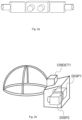
- a hemisphere 601 around a surface normal 602 at the point P is considered, as shown in FIG. 6 a .
- This surface hemisphere 601 is then spatially partitioned into a pre-defined number of solid angles 603 .
- the number of partitions may vary from point to point in the scene geometry.
- Average radiance or other representative radiance value at the point P is computed for each solid angle 603 using methods such as a known ray tracing method, a known path tracing method or other current or future variations of these.
- the computed values are used to fill a two dimensional matrix, an example of which is shown in FIG. 6 b with reference 610 after the mapping process has been done. By encoding this matrix for each point in the scene geometry, for a given orientation of a viewpoint, the value that is to be rendered can be easily retrieved by using the viewpoint's normal value.
- the redundancy exhibited by the PR matrix 610 of a point P depends on the nature of the material the point P belongs to. For example, a point on a material that is highly diffused will exhibit high redundancy, and a point that is on a purely reflected surface may exhibit a much lower redundancy. In other words, the efficiency of compression of a PR matrix is dependent on the nature of material it belongs to.
- a rendering application may compromise between compression efficiency and accessibility.
- various embodiments are described on how an encoder may choose to compress a scene where PR matrix has been evaluated for all points in the scene.
- each point in a texture map of a scene is represented by a small PR matrix.
- the size of the PR matrix is chosen such that it can be coded using a transform size(s) supported by the encoder (e.g. 8 ⁇ 8, 16 ⁇ 16, 32 ⁇ 32 or 64 ⁇ 64).
- a transform size(s) supported by the encoder e.g. 8 ⁇ 8, 16 ⁇ 16, 32 ⁇ 32 or 64 ⁇ 64.
- FIG. 7 illustrates a 3 ⁇ 3 patch of model points encoded as nine 8 ⁇ 8 Transform Units (TU) 701 , each TU coding 64 different viewing angles around the normal vector of the respective model point.
- TU Transform Unit
- multiple PR matrices for respective multiple points in the scene can be packed into a larger matrix having a size suitable for encoding.
- four PR matrices representing four adjacent pixels in the texture map may be packed into one coding transform unit of an HEVC encoder. The packing may occur after downscaling of the PR matrices.
- the packing of multiple PR matrices into one transform unit (TU) may be useful in several cases: where the surface material is more diffuse and the reflected colour does not change so rapidly depending on the viewing angle, or where the rendering application caters to a limited viewing volume, and only those pixels representing surfaces that are closer to the viewing volume require higher resolution, but those that are further away may require less resolution.
- FIG. 8 illustrates a 6 ⁇ 6 patch of model points encoded into the nine 8 ⁇ 8 TUs 801 , each TU containing four points, but with only 16 viewing directions each.
- neighbouring pixels can be highly correlated for any given viewing angle, whereupon the PR matrices of neighbouring pixels can be interleaved on a block basis before being handed over to the encoder.
- FIG. 9 illustrates the data of FIG. 8 being rearranged by interleaving for improved coherence and better compression.
- each individual value of a PR matrix for every pixel in the texture map can be layered.
- Such a strategy may be useful in a rendering application that desires to optimize the data to be decoded (see FIG. 10 showing a layered image). There can be multiple streams of these layers as well.
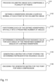
- FIG. 11 is a flowchart illustrating a method comprising processing 1101 volumetric image data comprising a plurality of points; defining 1102 a hemisphere around a surface normal at each point in the volumetric image; partitioning 1103 each of the defined hemispheres spatially into a predefined number of angles; determining 1104 a representative radiance value for each angle of the predefined number of angles of a defined hemisphere; generating 1105 a matrix for a point storing the determined representative radiance values; and encoding 1106 the generated matrix for the point for video compression.
- An apparatus comprises means for processing volumetric image data comprising a plurality of points; means for defining a hemisphere around a surface normal at each point in the volumetric image; means for partitioning each of the defined hemispheres spatially into a predefined number of angles; means for determining a representative radiance value for each angle of the predefined number of angles of a defined hemisphere; means for generating a matrix for a point storing the determined representative radiance values; and means for encoding the generated matrix for the point for video compression.
- the means comprises at least one processor, and a memory including a computer program code, wherein the processor may further comprise processor circuitry.
- the memory and the computer program code are configured to, with the at least one processor, cause the apparatus to perform the method for encoding.
- the computer program code comprises one or more operational characteristics. Said operational characteristics are being defined through configuration by said computer based on the type of said processor, wherein a system is connectable to said processor by a bus, wherein a programmable operational characteristic of the system comprises
- the various embodiments may provide advantages.
- the present embodiments enable storage of “full” hemisphere of radiance for the points.
- the management of multi-view/radiance from different angles is easily managed.
- the storing of the hemisphere data can be changed based on blocks, for bandwidth, quality and content needs.
- a device may comprise circuitry and electronics for handling, receiving and transmitting data, computer program code in a memory, and a processor that, when running the computer program code, causes the device to carry out the features of an embodiment.
- a network device like a server may comprise circuitry and electronics for handling, receiving and transmitting data, computer program code in a memory, and a processor that, when running the computer program code, causes the network device to carry out the features of an embodiment.
Landscapes
- Engineering & Computer Science (AREA)
- Multimedia (AREA)
- Signal Processing (AREA)
- Computer Graphics (AREA)
- Physics & Mathematics (AREA)
- General Physics & Mathematics (AREA)
- Theoretical Computer Science (AREA)
- Compression Or Coding Systems Of Tv Signals (AREA)
Abstract
Description
Claims (19)
Applications Claiming Priority (1)
| Application Number | Priority Date | Filing Date | Title |
|---|---|---|---|
| PCT/FI2018/050335 WO2019215377A1 (en) | 2018-05-07 | 2018-05-07 | A method and technical equipment for encoding and decoding volumetric video |
Publications (2)
| Publication Number | Publication Date |
|---|---|
| US20210235117A1 US20210235117A1 (en) | 2021-07-29 |
| US11653024B2 true US11653024B2 (en) | 2023-05-16 |
Family
ID=68466912
Family Applications (1)
| Application Number | Title | Priority Date | Filing Date |
|---|---|---|---|
| US17/050,935 Active US11653024B2 (en) | 2018-05-07 | 2018-05-07 | Method and technical equipment for encoding and decoding volumetric video |
Country Status (3)
| Country | Link |
|---|---|
| US (1) | US11653024B2 (en) |
| EP (1) | EP3791592A4 (en) |
| WO (1) | WO2019215377A1 (en) |
Families Citing this family (1)
| Publication number | Priority date | Publication date | Assignee | Title |
|---|---|---|---|---|
| EP4294010B1 (en) * | 2022-06-16 | 2025-03-19 | Axis AB | Camera system and method for encoding two video image frames captured by a respective one of two image sensors |
Citations (10)
| Publication number | Priority date | Publication date | Assignee | Title |
|---|---|---|---|---|
| WO1998049667A2 (en) | 1997-04-28 | 1998-11-05 | Board Of Trustees, Leland Stanford, Jr. University | Method and system for light field rendering |
| US20020159628A1 (en) | 2001-04-26 | 2002-10-31 | Mitsubishi Electric Research Laboratories, Inc | Image-based 3D digitizer |
| US20030071813A1 (en) * | 1996-06-05 | 2003-04-17 | Alessandro Chiabrera | Three-dimensional display system: apparatus and method |
| US20040041816A1 (en) | 2002-05-31 | 2004-03-04 | Kabushiki Kaisha Toshiba | High-dimensional texture drawing apparatus, high-dimensional texture compressing apparatus, high-dimensional texture drawing system, high-dimensional texture drawing method, and high-dimensional texture drawing program |
| US20060143142A1 (en) | 2003-07-25 | 2006-06-29 | Vasilescu Manuela A O | Logic arrangement, data structure, system and method for multilinear representation of multimodal data ensembles for synthesis, rotation and compression |
| US20070257913A1 (en) | 2002-03-21 | 2007-11-08 | Microsoft Corporation | Graphics image rendering with radiance self-transfer for low-frequency lighting environments |
| US20130106855A1 (en) | 2008-06-16 | 2013-05-02 | Julian Urbach | Re-utilization of render assets for video compression |
| US9786062B2 (en) * | 2013-05-06 | 2017-10-10 | Disney Enterprises, Inc. | Scene reconstruction from high spatio-angular resolution light fields |
| US20180097867A1 (en) | 2015-04-15 | 2018-04-05 | Lytro, Inc. | Video compression with adaptive view-dependent lighting removal |
| US20190371051A1 (en) * | 2017-01-13 | 2019-12-05 | Interdigital Vc Holdings, Inc. | Method, apparatus and stream for immersive video format |
-
2018
- 2018-05-07 WO PCT/FI2018/050335 patent/WO2019215377A1/en not_active Ceased
- 2018-05-07 US US17/050,935 patent/US11653024B2/en active Active
- 2018-05-07 EP EP18917954.2A patent/EP3791592A4/en not_active Ceased
Patent Citations (10)
| Publication number | Priority date | Publication date | Assignee | Title |
|---|---|---|---|---|
| US20030071813A1 (en) * | 1996-06-05 | 2003-04-17 | Alessandro Chiabrera | Three-dimensional display system: apparatus and method |
| WO1998049667A2 (en) | 1997-04-28 | 1998-11-05 | Board Of Trustees, Leland Stanford, Jr. University | Method and system for light field rendering |
| US20020159628A1 (en) | 2001-04-26 | 2002-10-31 | Mitsubishi Electric Research Laboratories, Inc | Image-based 3D digitizer |
| US20070257913A1 (en) | 2002-03-21 | 2007-11-08 | Microsoft Corporation | Graphics image rendering with radiance self-transfer for low-frequency lighting environments |
| US20040041816A1 (en) | 2002-05-31 | 2004-03-04 | Kabushiki Kaisha Toshiba | High-dimensional texture drawing apparatus, high-dimensional texture compressing apparatus, high-dimensional texture drawing system, high-dimensional texture drawing method, and high-dimensional texture drawing program |
| US20060143142A1 (en) | 2003-07-25 | 2006-06-29 | Vasilescu Manuela A O | Logic arrangement, data structure, system and method for multilinear representation of multimodal data ensembles for synthesis, rotation and compression |
| US20130106855A1 (en) | 2008-06-16 | 2013-05-02 | Julian Urbach | Re-utilization of render assets for video compression |
| US9786062B2 (en) * | 2013-05-06 | 2017-10-10 | Disney Enterprises, Inc. | Scene reconstruction from high spatio-angular resolution light fields |
| US20180097867A1 (en) | 2015-04-15 | 2018-04-05 | Lytro, Inc. | Video compression with adaptive view-dependent lighting removal |
| US20190371051A1 (en) * | 2017-01-13 | 2019-12-05 | Interdigital Vc Holdings, Inc. | Method, apparatus and stream for immersive video format |
Non-Patent Citations (8)
| Title |
|---|
| "Real-time Rendering with Compressed Animated Light Fields", Disney Research Studios, May 2017, 9 pages. |
| Cabral et al., "Reflection Space Image Based Rendering", Proceedings of the 26th annual conference on Computer graphics and interactive techniques, 1999, pp. 165-171. |
| Chen, Wei-Chao, et al., "Light Field Mapping: Efficient Representation and Hardware Rendering of Surface Light Fields", ACM Transactions on Graphics, ACM, NY, US, vol. 21, No. 3, Jul. 1, 2002, pp. 447-456. |
| Filip et al., "Bidirectional Texture Function Modeling: A State of the Art Survey", IEEE Transactions on Pattern Analysis and Machine Intelligence, vol. 31, No. 11, Nov. 2009, pp. 1921-1940. |
| International Search Report and Written Opinion received for corresponding Patent Cooperation Treaty Application No. PCT/FI2018/050335, dated Mar. 28, 2019, 16 pages. |
| Miller, Gavin, Dr., et al., "Lazy decompression of surface light fields for precomputed global illumination", Eurographics, Jan. 1, 1998, pp. 281-292. |
| Nishino et al., "Determining Reflectance Parameters and Illumination Distribution from a Sparse Set of Images for View-dependent Image Synthesis", Proceedings Eighth IEEE International Conference on Computer Vision. ICCV, 2001, pp. 1-8. |
| Vasilescu et al., "TensorTextures: Multilinear Image-Based Rendering", ACM Transactions on Graphics, 2004, pp. 336-342. |
Also Published As
| Publication number | Publication date |
|---|---|
| EP3791592A1 (en) | 2021-03-17 |
| US20210235117A1 (en) | 2021-07-29 |
| EP3791592A4 (en) | 2021-12-08 |
| WO2019215377A1 (en) | 2019-11-14 |
Similar Documents
| Publication | Publication Date | Title |
|---|---|---|
| US11599968B2 (en) | Apparatus, a method and a computer program for volumetric video | |
| US11109066B2 (en) | Encoding and decoding of volumetric video | |
| US11202086B2 (en) | Apparatus, a method and a computer program for volumetric video | |
| US11405643B2 (en) | Sequential encoding and decoding of volumetric video | |
| US11430156B2 (en) | Apparatus, a method and a computer program for volumetric video | |
| US10567464B2 (en) | Video compression with adaptive view-dependent lighting removal | |
| JP6501904B2 (en) | Spherical video streaming | |
| US11218683B2 (en) | Method and an apparatus and a computer program product for adaptive streaming | |
| JP7499182B2 (en) | Method, apparatus and stream for volumetric video format - Patents.com | |
| US12096027B2 (en) | Method, an apparatus and a computer program product for volumetric video encoding and decoding | |
| US11463681B2 (en) | Encoding and decoding of volumetric video | |
| US20180310025A1 (en) | Method and technical equipment for encoding media content | |
| US20210337243A1 (en) | Video transmission method, video transmission device, video receiving method and video receiving device | |
| WO2019229293A1 (en) | An apparatus, a method and a computer program for volumetric video | |
| WO2019138163A1 (en) | A method and technical equipment for encoding and decoding volumetric video | |
| EP3540696B1 (en) | A method and an apparatus for volumetric video rendering | |
| WO2019115867A1 (en) | An apparatus, a method and a computer program for volumetric video | |
| WO2019077199A1 (en) | An apparatus, a method and a computer program for volumetric video | |
| EP3729805B1 (en) | Method and apparatus for encoding and decoding volumetric video data | |
| WO2018109265A1 (en) | A method and technical equipment for encoding media content | |
| US11653024B2 (en) | Method and technical equipment for encoding and decoding volumetric video | |
| US20200311978A1 (en) | Image encoding method and technical equipment for the same | |
| WO2019008233A1 (en) | A method and apparatus for encoding media content |
Legal Events
| Date | Code | Title | Description |
|---|---|---|---|
| AS | Assignment |
Owner name: NOKIA TECHNOLOGIES OY, FINLAND Free format text: ASSIGNMENT OF ASSIGNORS INTEREST;ASSIGNORS:MALAMAL VADAKITAL, VINOD KUMAR;ROIMELA, KIMMO;PYSTYNEN, JOHANNES;SIGNING DATES FROM 20190822 TO 20190827;REEL/FRAME:054180/0050 |
|
| FEPP | Fee payment procedure |
Free format text: ENTITY STATUS SET TO UNDISCOUNTED (ORIGINAL EVENT CODE: BIG.); ENTITY STATUS OF PATENT OWNER: LARGE ENTITY |
|
| STPP | Information on status: patent application and granting procedure in general |
Free format text: NON FINAL ACTION MAILED |
|
| STPP | Information on status: patent application and granting procedure in general |
Free format text: RESPONSE TO NON-FINAL OFFICE ACTION ENTERED AND FORWARDED TO EXAMINER |
|
| STPP | Information on status: patent application and granting procedure in general |
Free format text: FINAL REJECTION MAILED |
|
| STPP | Information on status: patent application and granting procedure in general |
Free format text: ADVISORY ACTION MAILED |
|
| STPP | Information on status: patent application and granting procedure in general |
Free format text: DOCKETED NEW CASE - READY FOR EXAMINATION |
|
| STPP | Information on status: patent application and granting procedure in general |
Free format text: NON FINAL ACTION MAILED |
|
| STPP | Information on status: patent application and granting procedure in general |
Free format text: RESPONSE TO NON-FINAL OFFICE ACTION ENTERED AND FORWARDED TO EXAMINER |
|
| STCF | Information on status: patent grant |
Free format text: PATENTED CASE |