US11651554B2 - Systems and methods for synthetic image generation - Google Patents
Systems and methods for synthetic image generation Download PDFInfo
- Publication number
- US11651554B2 US11651554B2 US17/444,122 US202117444122A US11651554B2 US 11651554 B2 US11651554 B2 US 11651554B2 US 202117444122 A US202117444122 A US 202117444122A US 11651554 B2 US11651554 B2 US 11651554B2
- Authority
- US
- United States
- Prior art keywords
- images
- model
- class
- image
- anomaly
- Prior art date
- Legal status (The legal status is an assumption and is not a legal conclusion. Google has not performed a legal analysis and makes no representation as to the accuracy of the status listed.)
- Active, expires
Links
Images


Classifications
-
- G—PHYSICS
- G06—COMPUTING OR CALCULATING; COUNTING
- G06T—IMAGE DATA PROCESSING OR GENERATION, IN GENERAL
- G06T19/00—Manipulating 3D models or images for computer graphics
-
- G—PHYSICS
- G06—COMPUTING OR CALCULATING; COUNTING
- G06T—IMAGE DATA PROCESSING OR GENERATION, IN GENERAL
- G06T19/00—Manipulating 3D models or images for computer graphics
- G06T19/20—Editing of 3D images, e.g. changing shapes or colours, aligning objects or positioning parts
-
- G—PHYSICS
- G06—COMPUTING OR CALCULATING; COUNTING
- G06F—ELECTRIC DIGITAL DATA PROCESSING
- G06F18/00—Pattern recognition
- G06F18/20—Analysing
- G06F18/21—Design or setup of recognition systems or techniques; Extraction of features in feature space; Blind source separation
- G06F18/214—Generating training patterns; Bootstrap methods, e.g. bagging or boosting
- G06F18/2148—Generating training patterns; Bootstrap methods, e.g. bagging or boosting characterised by the process organisation or structure, e.g. boosting cascade
-
- G—PHYSICS
- G06—COMPUTING OR CALCULATING; COUNTING
- G06F—ELECTRIC DIGITAL DATA PROCESSING
- G06F30/00—Computer-aided design [CAD]
- G06F30/10—Geometric CAD
- G06F30/12—Geometric CAD characterised by design entry means specially adapted for CAD, e.g. graphical user interfaces [GUI] specially adapted for CAD
-
- G06K9/6257—
-
- G—PHYSICS
- G06—COMPUTING OR CALCULATING; COUNTING
- G06N—COMPUTING ARRANGEMENTS BASED ON SPECIFIC COMPUTATIONAL MODELS
- G06N3/00—Computing arrangements based on biological models
- G06N3/02—Neural networks
-
- G—PHYSICS
- G06—COMPUTING OR CALCULATING; COUNTING
- G06T—IMAGE DATA PROCESSING OR GENERATION, IN GENERAL
- G06T15/00—3D [Three Dimensional] image rendering
- G06T15/04—Texture mapping
-
- G—PHYSICS
- G06—COMPUTING OR CALCULATING; COUNTING
- G06T—IMAGE DATA PROCESSING OR GENERATION, IN GENERAL
- G06T15/00—3D [Three Dimensional] image rendering
- G06T15/10—Geometric effects
- G06T15/20—Perspective computation
-
- G—PHYSICS
- G06—COMPUTING OR CALCULATING; COUNTING
- G06T—IMAGE DATA PROCESSING OR GENERATION, IN GENERAL
- G06T2219/00—Indexing scheme for manipulating 3D models or images for computer graphics
- G06T2219/20—Indexing scheme for editing of 3D models
- G06T2219/2012—Colour editing, changing, or manipulating; Use of colour codes
-
- G—PHYSICS
- G06—COMPUTING OR CALCULATING; COUNTING
- G06T—IMAGE DATA PROCESSING OR GENERATION, IN GENERAL
- G06T2219/00—Indexing scheme for manipulating 3D models or images for computer graphics
- G06T2219/20—Indexing scheme for editing of 3D models
- G06T2219/2021—Shape modification
Definitions
- the present invention relates to image recognition, and more particularly to an unsupervised cross-domain synthetic image generation system configured to train an object detection system.
- Object detection systems implementing artificial intelligence are trained to accurately detect target objects using large realistic visual data sets, which have high accuracy, specificity, and diversity.
- High accuracy is achieved by reducing biases from human labelers.
- High specificity is achieved by capturing different images of the target object in various environmental conditions.
- High diversity is achieved by including various images of the target object from various view angles and perspectives.
- developing large realistic visual data sets with high accuracy, specificity, and diversity is a challenge, especially using conventional methods of manually taking pictures of the target objects using cameras, and having a human operator label each image with a ground truth target object class.
- An image generation system for unsupervised cross-domain image generation relative to a first image domain and a second image domain.
- the image generation system comprises a processor, and a memory storing instructions.
- the processor executes the instructions to cause the system to: generate a graph data structure to store in the memory, the graph data structure comprising a plurality of connected nodes, the connected nodes comprising one or more object nodes representing components and one or more part characteristic nodes representing part characteristics for each component, and one or more anomaly node representing potential anomalies for each part characteristic; receive a 3D computer aided design (CAD) model comprising 3D model images of a target object; based on the 3D CAD model of the target object and the graph data structure, generate a plurality of augmented CAD models of the target object comprising a plurality of data sets, each data set respectively corresponding to an associated one of a plurality of attribute classes, each data set comprising a plurality of 2D model images; input the plurality of data sets into a generative adversarial network comprising
- the plurality of attribute classes includes an anomaly class.
- the processor is configured to generate the plurality of augmented CAD models by adding one or more anomalies into the 3D CAD model augmented based on the graph data structure, and rendering 2D model images of an anomaly class data set of the anomaly class using the augmented 3D CAD model.
- FIG. 1 is a general schematic diagram illustrating an overview of a synthetic image generation computing system for generating synthetic photorealistic images, according to an embodiment of the subject disclosure.
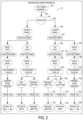
- FIG. 2 is a schematic diagram illustrating a graph data structure of a knowledge graph engine according to an embodiment of the subject disclosure.
- FIG. 3 is a schematic diagram illustrating the generation of the anomaly data set of the augmented CAD models in accordance with a graph data structure generated by a knowledge graph engine according to an embodiment of the subject disclosure.
- FIG. 4 is a detailed schematic diagram illustrating the inputs and outputs of the generative adversarial network of the system of FIG. 1 .
- FIG. 5 is a schematic diagram illustrating the training of the generator model of the synthetic image generation computing system of FIG. 1 .
- FIG. 6 is a schematic diagram illustrating the training of the discriminator model of the synthetic image generation computing system of FIG. 1 .
- FIG. 7 is a flowchart of a method for using the generator model of the generative adversarial network to generate synthetic photorealistic images according to an embodiment of the subject disclosure.
- FIG. 8 is a flowchart of a method for training the generator model of the generative adversarial network according to an embodiment of the subject disclosure.
- FIG. 9 is a flowchart of a method for training the discriminator model of the generative adversarial network according to an embodiment of the subject disclosure.
- FIG. 10 is a schematic diagram illustrating an exemplary computing system that can be used to implement the synthetic image generation computing system of FIG. 1 .
- a synthetic image generation system 10 is provided for use in generating synthetic photorealistic images 40 .
- the synthetic image generation system 10 comprises a synthetic image generation computing device 12 including a processor 14 , volatile memory 16 , an input/output module 18 , and non-volatile memory 24 storing an application 26 including a knowledge graph engine 27 , a synthetic image generator 30 , augmented CAD models 32 , and a cycle generative adversarial network (GAN) 34 .
- GAN cycle generative adversarial network
- the synthetic image generation computing device 12 is configured to convert inputted 3D CAD models 28 into synthetic photorealistic images 40 using image-to-image translation or transfer, converting an image from one representation to another.
- the image-to-image translation or transfer is performed from 2D model images derived from a 3D CAD model 28 into synthetic photorealistic images 40 .
- a communications bus 20 can operatively couple the processor 14 , the input/output module 18 , and the volatile memory 16 to the non-volatile memory 24 .
- the synthetic image generator 30 , augmented CAD models 32 , and the generative adversarial network 34 are depicted as hosted (i.e., executed) at one computing device 12 , it will be appreciated that the knowledge graph engine 27 , synthetic image generator 30 , augmented CAD models 32 , and the generative adversarial network 34 can alternatively be hosted across a plurality of computing devices to which the computing device 12 is communicatively coupled via a network 22 .
- a client computing device 86 can be provided, which is operatively coupled to the synthetic image generation computing device 12 .
- the network 22 can take the form of a local area network (LAN), wide area network (WAN), wired network, wireless network, personal area network, or a combination thereof, and can include the Internet.
- the computing device 12 comprises a processor 14 and a non-volatile memory 24 configured to store the synthetic image generator 30 , knowledge graph engine 27 , augmented CAD models 32 , and the generative adversarial network 34 in non-volatile memory 24 .
- Non-volatile memory 24 is memory that retains instructions stored data even in the absence of externally applied power, such as FLASH memory, a hard disk, read only memory (ROM), electrically erasable programmable memory (EEPROM), etc.
- the instructions include one or more programs, including the synthetic image generator 30 , knowledge graph engine 27 , augmented CAD models 32 , the generative adversarial network 34 , and data used by such programs sufficient to perform the operations described herein.
- the instructions cause the processor 14 to execute the synthetic image generator 30 to receive, from the application client 26 A, a 3D CAD model 28 comprising 3D model images of a target object.
- the synthetic image generator 30 Based on the 3D CAD model 28 of the target object, the synthetic image generator 30 generates a plurality of augmented CAD models 32 of the target object comprising a plurality of data sets 32 a - d , each data set 32 a - d respectively corresponding to an associated one of a plurality of attribute classes including an anomaly class, each data set 32 a - d comprising a plurality of 2D model images.
- the processor 14 is configured to generate the plurality of augmented CAD models 32 by adding one or more anomalies into the 3D CAD model 28 augmented based on the graph data structure 23 , and rendering 2D model images of an anomaly class data set 32 a of the anomaly class using the augmented 3D CAD model 32 .
- a plurality of anomalies are added into the 3D CAD model 28 .
- the knowledge graph engine 27 generates a graph data structure 23 , or a graph database of nodes and edges connecting nodes storing target object data, which is configured to be processed by the synthetic image generator 30 as instructions for generating the plurality of augmented CAD models 32 , as further explained below in relation to FIG. 2 .
- the knowledge graph engine 27 is configured to store the graph data structure 23 into non-volatile memory 24 , and package the graph data structure 23 into metadata 29 which is sent to the synthetic image generator 30 .
- the metadata 29 is parsed by the synthetic image generator 30 to read instructions on how to generate the plurality of augmented CAD models 32 . Accordingly, the synthetic image generator 30 follows the instructions contained in the graph data structure 23 to generate the plurality of data sets 32 a - d comprising a plurality of 2D model images derived from the 3D CAD model 28 .
- the knowledge graph engine 27 can generate the graph data structure 23 by processing target parts data 25 of the target object and converting the target parts data 25 into the graph data structure 23 .
- the target parts data 25 can be manufacturing inspection data in tabular form for the parts of the target object.
- the target parts data 25 can include statistical information regarding the probabilities or frequencies of occurrence of anomalies in the parts of the target object.
- the target parts data 25 can be incorporated into the 3D CAD model 28 or associated with the 3D CAD model 28 so that the parts in the target parts data 25 correspond to the parts in the 3D CAD model 28 .
- the knowledge graph engine 27 can receive the target parts data 25 from the application client 26 A.
- the plurality of data sets 32 a - d are inputted into a generative adversarial network 34 comprising a plurality of generators 36 a - d respectively corresponding to the plurality of attribute classes (Class I-IV) and a plurality of discriminators 38 a - d respectively corresponding to the plurality of generators 36 a - d .
- the plurality of attribute classes can include at least one of an anomaly class, a material textures class, an environmental conditions class, or a perspective views class, for example.
- the client computing device 86 can execute an application client 26 A to send at least a 3D CAD model 28 to the computing device 12 via a network 22 .
- the generative adversarial network 34 generates synthetic photorealistic images 40 of the target objects using the plurality of generators 36 a - d .
- the synthetic photorealistic images 40 include attributes in accordance with the plurality of data sets 32 a - d corresponding to the plurality of attribute classes (Class I-IV).
- the application 26 outputs the synthetic photorealistic images 40 of the target object via the network 22 to the client computing device 86 , which subsequently receives the synthetic photorealistic images 40 from the computing device 12 as output.
- the synthetic photorealistic images 40 are then displayed as graphical output 92 on the graphical user interface 88 of the client computing device 86 .
- the synthetic photorealistic images 40 can also be used to train an anomaly detection artificial intelligence model 96 of an anomaly detection computing device 94 to detect anomalies on target objects.
- the client computing device 86 can execute the application client 26 A to send a photorealistic image set 44 of the target object to train the generators 36 a - d and discriminators 38 a - d of the generative adversarial network 34 , as explained in detail below with reference to FIGS. 4 , 5 , 7 , and 8 .
- the processor 14 is a microprocessor that includes one or more of a central processing unit (CPU), a graphical processing unit (GPU), an application specific integrated circuit (ASIC), a system on chip (SOC), a field-programmable gate array (FPGA), a logic circuit, or other suitable type of microprocessor configured to perform the functions recited herein.
- the system 10 further includes volatile memory 16 such as random access memory (RAM), static random access memory (SRAM), dynamic random access memory (DRAM), etc., which temporarily stores data only for so long as power is applied during execution of programs.
- RAM random access memory
- SRAM static random access memory
- DRAM dynamic random access memory
- NVRAM non-volatile random access memory
- a graphical user interface (GUI) 88 of the client computing device 86 receives a user input 90 . Responsive to the user input 90 , the application client 26 A of the client computing device 86 sends a 3D CAD model 28 to the synthetic image generator 30 , which outputs augmented CAD models 32 with a plurality of data sets 32 a - d based on the 3D CAD model 28 .
- the plurality of augmented CAD models 32 can include a class I data set 32 a , a class II data set 32 b , a class III data set 32 c , and a class IV data set 32 d . It will be appreciated that the number of data sets and the number of attribute classes are not particularly limited.
- the data sets 32 a - d of the augmented CAD models 32 are inputted into the generative adversarial network 34 , which comprises a generator model 36 including a plurality of generators 36 a - d and a discriminator model 38 including a plurality of discriminators 38 a - d .
- the generative adversarial network 34 comprises neural networks.
- the generators 36 a - d can be implemented by convolutional neural networks, and the discriminators 38 a - d can be implemented by deconvolutional neural networks.
- Each data set 32 a - d is inputted into the respective generator corresponding to the attribute class of each data set. Therefore, in this example, the class I data set 32 a is inputted into the class I generator 36 a , the class II data set 32 b is inputted into the class II generator 36 b , the class III data set 32 c is inputted into the class III generator 36 c , and the class IV data set 32 d is inputted into the class IV generator 36 d .
- the generator models 36 a - d are configured to generate synthetic photorealistic images 40 based on the data sets 32 a - d .
- the discriminator models 38 a - d are used to train the generator models 36 a - d during a training process.
- the graph data structure 23 comprises edges 23 b , 23 d , 23 f , 23 i , 23 j , 23 m , 23 n , 23 r , 23 s , 23 t connecting nodes 23 a , 23 c , 23 e , 23 g , 23 h , 23 k , 231 , 23 o , 23 p , 23 q , 23 u , 23 v , 23 w in a complex web of relationships forming a branching tree structure.
- the connecting nodes 23 a , 23 c , 23 e , 23 g , 23 h , 23 k , 231 , 23 o , 23 p , 23 q , 23 u , 23 v , 23 w comprise one or more object nodes 23 a , 23 c , 23 e representing components and one or more part characteristic nodes 23 g , 23 h , 23 k , 231 representing part characteristics for each component, and one or more anomaly nodes 23 o , 23 p , 23 q representing potential anomalies for each part characteristic and associated with one or more anomaly parameter nodes 23 u , 23 v , 23 w including anomaly parameters for depicting the anomalies on the augmented CAD models 32 .
- the graph data structure 23 indicates probabilities of occurrence of each anomaly represented by the one or more anomaly nodes 23 o , 23 p , 23 q .
- a portion of the graph data structure 23 for the left wing assembly is depicted showing the probabilities of the occurrence of various anomaly types on the left wing assembly: the thickness of the base coat of the upper panel surface has a 45% probability of an under/over painting anomaly; the markings of the top coat of the upper panel surface has a 50% probability of being mislocated and a 35% probability of being missing or omitted; the markings of the top coat of the lower panel surface has a 45% probability of being missing or omitted and a 50% probability of being mislocated; and the thickness of the base coat of the lower panel surface has a 35% probability of being under/over painted.
- the synthetic image generator 30 generates anomalies in the anomaly data set 32 a of the augmented CAD models 32 in accordance with the probabilities that are indicated in the graph data structure 23 .
- the 2D model images of the anomaly class data set 32 a are rendered to depict the anomalies represented by the one or more anomaly nodes 23 o , 23 p , 23 q based on the probabilities indicated by the graph data structure 23 , so that proportions of the 2D model images depicting the anomalies match the probabilities indicated by the graph data structure 23 .
- the synthetic photorealistic images 40 outputted by the generative adversarial network 34 can include the types of anomalies on the target object at the frequencies that reflect the actual anomalies that are actually observed on the target object in the real manufacturing environment.
- the graph data structure 23 can also include additional instructions on how to reproduce the anomalies or anomalies on the augmented CAD models 32 .
- additional instructions on how to reproduce the anomalies or anomalies on the augmented CAD models 32 .
- a depth and size of the dent will also be indicated so that the synthetic image generator 30 can accurately reproduce the anomaly on the 2D model images.
- offsets are indicated for the mislocated markings anomalies and under/over painted base coat anomalies so that these anomalies can be reproduced accurately by the synthetic image generator 30 on the 2D model images.
- a set of synthetic photorealistic images 40 of the target object can be generated containing depictions of the types of anomalies on the target object at frequencies that are actually observed on the target object in the real manufacturing environment, so that an anomaly detection artificial intelligence model 96 can be trained with the synthetic photorealistic images 40 to detect anomalies on the target object with higher sensitivity and specificity.
- a schematic diagram depicts an example of how the synthetic image generator 30 parses the metadata 29 , comprising the packaged graph data structure 23 generated by the knowledge graph engine 27 , to generate the anomaly data set of the augmented CAD models 32 of the target object.
- the synthetic image generator 30 parses the graph data structure 23 , which indicates a 25% probability of an inward dent with a depth of 1 to 4 cm below the main doors on the right lower side surface of the fuselage.
- the synthetic image generator 30 generates the anomaly data set 32 a of the augmented CAD models 32 , so that 25% of the generated 2D model images of the fuselage includes an inward dent anomaly 32 aa at a depth of 1 to 4 cm below the main doors, and 75% of the 2D model images of the fuselage do not include this inward dent anomaly 32 aa .
- the depictions of the depth of the inward dent can be distributed in accordance with a prescribed statistical distribution.
- the graph data structure 23 can indicate that 25%, 40%, 15%, and 20% of the inward dents have depths of 1 cm, 2 cm, 3 cm, and 4 cm, respectively.
- the synthetic image generator 30 can generate the anomaly data set 32 a so that 25%, 40%, 15%, and 20% of the 2D model images depicting inward dents below the main doors on the fuselage have depths of 1 cm, 2 cm, 3 cm, and 4 cm, respectively.
- a schematic diagram depicts the inputs and outputs of the generators 36 a - d of the generative adversarial network 34 .
- the 3D CAD model 28 that is inputted into the synthetic image generator 30 is that of an aircraft component.
- the synthetic image generator 30 processes the 3D CAD model 28 to output augmented CAD models 32 comprising a class I data set 32 a , a class II data set 32 b , a class III data set 32 c , and a class IV data set 32 d .
- Each data set 32 a - d comprises a plurality of 2D model images derived from the 3D CAD model 28 .
- the plurality of 2D model images can comprise 2D pixelated images including pixel data.
- the class I data set 32 a is inputted into the class I generator 36 a , which performs an image style transfer on the class I data set 32 a to generate a plurality of class I synthetic photorealistic images 40 a .
- the class II data set 32 b is inputted into the class II generator 36 b , which performs an image style transfer on the class II data set 32 b to generate a plurality of class II synthetic photorealistic images 40 b .
- the class III data set 32 c is inputted into the class III generator 36 c , which performs an image style transfer on the class III data set 32 c to generate a plurality of class III synthetic photorealistic images 40 c .
- the class IV data set 32 d is inputted into the class IV generator 36 d , which performs an image style transfer on the class IV data set 32 d to generate a plurality of class IV synthetic photorealistic images 40 d.
- the synthetic image generator 30 has generated 2D model images in the class I data set by adding various anomalies into the 3D CAD model 28 in accordance with the graph data structure 23 and rendering the 2D model images from the 3D CAD model 28 with the added anomalies.
- the various anomalies can be added into the 3D CAD model 28 augmented based on the anomaly parameters in the anomaly parameter nodes 23 u , 23 v , 23 w , so that the 2D model images of the anomaly class data set 32 a are rendered to depict the anomalies represented by the one or more anomaly nodes 23 o , 23 p , 23 q based on the anomaly parameters 23 u , 23 v , 23 w included in the graph data structure 23 .
- the anomaly parameter nodes 23 u , 23 v , 23 w of the graph data structure 23 can instruct the synthetic image generator 30 to add a type A anomaly to the left wing of an airplane on 70% of the 2D model images and add a type B anomaly to the right wing of the airplane on 30% of the 2D model images.
- the graph data structure 23 can include other instructions prescribing the frequencies of the locations, sizes, and types of anomalies that appear on the 2D model images.
- the synthetic image generator 30 has generated 2D model images in the class II data set 32 b by adding various material textures into the 3D CAD model 28 in accordance with the graph data structure 23 and rendering the 2D model images from the 3D CAD model 28 with the added material textures.
- material textures refer to at least one of materials or textures.
- the synthetic image generator 30 has generated 2D model images in the class III data set 32 c by adding various environmental conditions (various lighting and atmospheric conditions, for example) into the 3D CAD model 28 in accordance with the graph data structure 23 and rendering the 2D model images from the 3D CAD model 28 with the added environmental conditions.
- the synthetic image generator 30 has generated 2D model images in the class IV data set 32 d by taking 2D model images of the 3D CAD model 28 from various perspective views in accordance with the graph data structure 23 and rendering the 2D model images of the 3D CAD model 28 from the various perspective views.
- the synthetic image generator 30 can selectively determine which data sets are outputted to the generative adversarial network 34 depending on the target application. For example, for dent detection applications in which synthetic photorealistic training images of dents on target objects with different material textures are to be generated, but the outputted training images are to be controlled for both environmental conditions and perspective views, the synthetic image generator 30 generates 2D model images in the class I data set 32 a and the class II data set 32 b , in which the images depict dents on different material textures of the target object, so that the generative adversarial network 34 can be trained to generate synthetic photorealistic images 40 of dents on different material textures of the target object.
- the class I generator 36 a and the class II generator 36 b of the generators would be used to generate the synthetic photorealistic images 40 .
- An inference script can be used by the synthetic image generator 30 to infer the target application and select the appropriate data sets to output to the generative adversarial network 34 , to prepare a set of synthetic photorealistic images having the appropriate content to train an object detection system for the target application.
- FIG. 5 a schematic diagram is provided illustrating a training phase for training each generator model 36 a - d in the generative adversarial network 34 .
- the generator 36 a receives input of the class I data set 32 a of the augmented CAD models 32 and class I photorealistic images 44 a as a first image domain input 32 a and a second image domain input 44 a , respectively.
- the training of the class I generator 36 a is depicted in this 2D model images, it will be appreciated that the training of the class II generator 36 b , the training of the class III generator 36 c , and the training of the class IV generator 36 d are performed similarly to the training of the class I generator 36 a .
- the class II photorealistic images 44 b and the class II data set 32 b are inputted into the class II generator 36 b .
- the class III photorealistic images 44 c and the class III data set 32 c are inputted into the class III generator 36 c .
- the class IV photorealistic images 44 d and the class IV data set 32 d are inputted into the class IV generator 36 d.
- the class I photorealistic images 44 a are those of anomalies on the target object, including photographs of anomalies of different types, sizes, and locations on the target object.
- Class II photorealistic images 44 b are those of various material textures on the target object, including photographs of various material textures on the target object.
- Class III photorealistic images 44 c are those taken of the target object under various lighting and atmospheric conditions.
- Class IV photorealistic images 44 d are those taken of the target object from various angles and perspective views. It will be appreciated that these are merely exemplary and many other types of classes can be utilized.
- the class I generator 36 a is trained to capture special characteristics of the 2D model images of the class I data set 32 a and translate them into synthetic photorealistic images.
- the first image domain input 32 a (labeled “real A” in FIG. 5 ) and the second image domain input 44 a (labeled “real B” in FIG. 5 ) are inputted into the class I generator model 36 a .
- the first image domain input 32 a is implemented as 2D model images in the class I data set 32 a of the augmented CAD models 32
- the second image domain input 44 a is implemented as class I photorealistic images 44 a in the photorealistic image set 44 .
- the first image generator 36 aa (G(A ⁇ B)) of the class I generator model 36 a converts the first image domain input 32 a into fake photorealistic images 46 (labeled “fake B” in FIG. 5 ).
- the first image generator 36 aa is configured to generate synthetic images (fake photorealistic images) 46 having a similar appearance to one or more of the photorealistic images 44 a in the second image domain while including a semantic content of one or more 2D model images in the class I data set 32 a depicting anomalies in the first image domain in accordance with an anomaly class data set 32 a in the augmented CAD models 32 of the target object.
- the second image generator 36 ab of the class I generator model 36 a converts the fake photorealistic images 46 into reconstituted 2D model images 48 (labeled “rec A” in FIG. 5 ).
- the second image generator 36 ab also converts the second image domain input 44 a into fake 2D model images 50 (labeled “fake A” in FIG. 5 ).
- the second image generator 36 ab is configured to generate synthetic images (fake 2D model images) 50 having a similar appearance to one or more of the 2D model images of the class I data set 32 a depicting anomalies in the first image domain while including semantic content of one or more photorealistic images 44 a in the second image domain.
- the first image generator 36 aa converts the fake 2D model images 50 into reconstituted photorealistic images 52 (labeled “rec B” in FIG. 5 ).
- the fake photorealistic images 46 are inputted into the first image discriminator 38 aa (D_A) of the class I discriminator 38 a , which outputs a first GAN loss 54 a for the first image generator 36 aa estimating the probability that the fake photorealistic images 46 are real photorealistic images.
- the first image discriminator 38 aa is configured to discriminate real photorealistic images 44 a in the second image domain against synthetic (fake) photorealistic images 46 generated by the first image generator 36 aa.
- the fake 2D model images 50 are inputted into the second image discriminator 38 ab (D_B) of the class I discriminator 38 a , which outputs a second GAN loss 54 b for the second image generator 36 ab estimating the probability that the fake 2D model images 50 are real 2D model images.
- a second image discriminator 38 ab configured to discriminate real 2D model images of the class I data set 32 a depicting anomalies in the first image domain against synthetic (fake) 2D model images 50 depicting anomalies generated by the second image generator 36 ab.
- the class I photorealistic images 44 a , the class I data set 32 a , the reconstituted 2D model images 48 , and the reconstituted photorealistic images 52 are also inputted into the cycle-consistency loss calculator 42 , which comprises a forward cycle-consistency loss calculator 42 a and a backward cycle-consistency loss calculator 42 b .
- the forward cycle-consistency loss calculator 42 a calculates a forward cycle-consistency loss 56 between the 2D model images of the class I data set 32 a and the reconstituted 2D model images 48 .
- the backward cycle-consistency loss calculator 42 b calculates a backward cycle-consistency loss 58 between the class I photorealistic images 44 a and the reconstituted photorealistic images 52 .
- the cycle-consistency loss calculations performed by the cycle-consistency loss calculator 42 can be those used in cycle GAN architectures used for performing unpaired image-to-image translation.
- the gradient calculator 60 combines the first GAN loss 54 a , the second GAN loss 54 b , the forward cycle-consistency loss 56 , and the backward cycle-consistency loss 58 to calculate gradients for the first image generator 36 aa and the second image generator 36 ab . Then, the gradient calculator 60 updates the weights for the first image generator 36 aa and the second image generator 36 ab in accordance with the calculated gradients.
- FIG. 6 a schematic diagram is provided illustrating a training phase for training each discriminator model 38 a - d in the generative adversarial network 34 respectively corresponding to the generator models 36 a - d .
- the class I discriminator receives input of the fake photorealistic images 46 and the fake 2D model images 50 outputted by the generator 36 a , the 2D model images of the class I data set 32 a , and the class I photorealistic images 44 a.
- the class II discriminator 38 b For the training of the class II discriminator 38 b , the class II photorealistic images 44 b and the class II data set 32 b are inputted into the class II discriminator 38 b along with fake photorealistic images 46 and the fake 2D model images 50 outputted by the class II generator 36 b .
- the class III photorealistic images 44 c and the class III data set 32 c are inputted into the class III discriminator 38 c , along with fake photorealistic images 46 and the fake 2D model images 50 outputted by the class III generator 36 c .
- the class IV photorealistic images 44 d and the class IV data set 32 d are inputted into the class IV discriminator 38 d along with fake photorealistic images 46 and the fake 2D model images 50 outputted by the class IV generator 36 d.
- the first image discriminator 38 aa distinguishes between the class I photorealistic images 44 a and fake photorealistic images 46 to calculate a real prediction probability 62 that the class I photorealistic images 44 a are real photorealistic images, and further calculate a fake prediction probability 64 that the fake photorealistic images 46 are fake photorealistic images.
- the loss function 66 calculates a real discriminator loss 68 based on the real prediction probability 62 , and further calculates a fake discriminator loss 70 based on the fake prediction probability 64 .
- the gradient calculator 72 combines the real discriminator loss 68 and the fake discriminator loss 70 to calculate a gradient for the first image discriminator 38 aa . Then the gradient calculator 72 updates the weights of the first image discriminator 38 aa in accordance with the calculated gradient.
- the second image discriminator 38 ab distinguishes between the fake 2D model images 50 outputted by the generator 36 a and the 2D model images of the class I data set 32 a , to calculate a real prediction probability 74 that the 2D model images of the class I data set 32 a are real 2D model images, and further calculate a fake prediction probability 76 that the fake 2D model images 50 are fake 2D model images.
- the loss function 78 calculates a real discriminator loss 80 based on the real prediction probability 74 , and further calculates a fake discriminator loss 82 based on the fake prediction probability 76 .
- the gradient calculator 84 combines the real discriminator loss 80 and the fake discriminator loss 82 to calculate a gradient for the second image discriminator 38 ab . Then the gradient calculator 84 updates the weights of the second image discriminator 38 ab in accordance with the calculated gradient.
- the losses are not particularly limited. For example, a mean squared error loss function or a binary cross entropy loss function can be used to calculate the losses.
- method 400 for translating a 3D CAD model of a target object into synthetic photorealistic images of the target object is described.
- the following description of method 400 is provided with reference to the software and hardware components described above and shown in FIGS. 1 - 3 . It will be appreciated that method 400 also can be performed in other contexts using other suitable hardware and software components.
- target parts data 25 is inputted into the knowledge graph engine 27 .
- a graph data structure 23 is generated based on the target parts data 25 and stored in memory.
- the graph data structure comprises a plurality of connected nodes, the connected nodes comprising one or more object nodes representing components and one or more part characteristic nodes representing part characteristics for each component, and one or more anomaly nodes representing potential anomalies for each part characteristic.
- the graph data structure is packaged into metadata 29 .
- a 3D CAD model 28 comprising 3D model images of a target object, and the metadata 29 from the knowledge graph engine 27 are inputted into the synthetic image generator 30 , which receives the 3D CAD model 28 and the metadata 29 .
- augmented CAD models 32 are generated, based on the 3D CAD model 28 of the target object and the graph data structure 23 , comprising a plurality of data sets 32 a - d , each data set 32 a - d respectively corresponding to an associated one of a plurality of attribute classes, each data set 32 a - d comprising a plurality of 2D model images.
- Step 410 can include steps 410 a - d : step 410 a of generating an anomaly class data set 32 a , step 410 b of generating a material textures class data set 32 b , step 410 c of generating an environmental conditions class data set 32 c , and step 410 d of generating a perspective views class data set 32 d . Accordingly, by generating 2D model images instead of 3D model images, processing power demands can be reduced.
- Step 410 a of generating an anomaly class data set 32 a includes step 410 aa of adding various anomalies into the 3D CAD model 28 augmented based on the graph data structure 23 , and step 410 ab of rendering 2D model images of an anomaly class data set 32 a of the anomaly class using the augmented CAD model 32 .
- the anomaly class data set 32 a can be generated with great diversity in the depictions of various anomalies in accordance with the graph data structure 23 .
- the diversity of various anomalies depicted in the anomaly class data set 32 a can accurately reflect the diversity of various anomalies that is actually encountered on the target object in the real manufacturing environment.
- Step 410 b of generating a material textures class data set 32 b can include step 410 ba of adding various material textures into the 3D CAD model 28 augmented in accordance with the graph data structure 23 , and step 410 bb of rendering 2D model images of the material textures class data set 32 b of the material textures class using the augmented CAD model 32 .
- the material textures class data set 32 b can be generated with great diversity in the depictions of various material textures in accordance with the graph data structure 23 .
- the diversity of various material textures depicted in the material textures class data set 32 b can accurately reflect the diversity of various material textures that is actually encountered on the target object in the real manufacturing environment.
- Step 410 c of generating an environmental conditions class data set 32 c can include step 410 ca of adding various environmental conditions into the 3D CAD model 28 augmented in accordance with the graph data structure 23 , and step 410 cb of rendering 2D model images of the environmental conditions class data set 32 c of the environmental conditions class using the augmented CAD model 32 .
- the environmental conditions class data set 32 c can be generated with great diversity in the depictions of various environmental conditions in accordance with the graph data structure 23 .
- the diversity of various environmental conditions depicted in the environmental conditions class data set 32 c can accurately reflect the diversity of various environmental conditions that is actually encountered for the target object in the real manufacturing environment.
- Step 410 d of generating a perspective views class data set 32 d can include step 410 da of taking 2D model images of the 3D CAD model 28 from various perspective views augmented in accordance with the graph data structure 23 , and step 410 db of rendering 2D model images of the perspective views class data set 32 d of the perspective views class using the augmented CAD model 32 . Accordingly, the perspective views class data set 32 d can be generated with great diversity in the depictions of various perspective views in accordance with the graph data structure 23 .
- the data sets 32 a - d are inputted into a generative adversarial network 34 comprising a plurality of image generators 36 a - d respectively corresponding to the plurality of attribute classes and a plurality of image discriminators 38 a - d respectively corresponding to the plurality of image generators 36 a - d .
- the synthetic photorealistic images 40 of the target object are generated by the plurality of image generators 36 a - d .
- the generated synthetic photorealistic images 40 include attributes in accordance with the plurality of data sets 32 a - d corresponding to the plurality of attribute classes.
- the synthetic photorealistic images 40 of the target object are outputted on a graphical user interface 88 of a client computing device 86 .
- the synthetic photorealistic images 40 of the target object are inputted into an anomaly detection artificial intelligence model 96 to train the anomaly detection artificial intelligence model 96 to detect anomalies on the target object.
- method 500 for training the generator model 36 of the generative adversarial network 34 is described.
- the following description of method 500 is provided with reference to the software and hardware components described above and shown in FIGS. 1 - 4 . It will be appreciated that method 500 also can be performed in other contexts using other suitable hardware and software components.
- Step 502 fake photorealistic images 46 and reconstituted 2D model images 48 are generated.
- Step 502 includes step 502 a of inputting real 2D model images 32 a (real A) of a data set of the augmented CAD models 32 into the first image generator 36 aa (G_A), step 502 b of, via the first image generator 36 aa (G_A), translating the real 2D model images 32 a (real A) into fake photorealistic images 46 (fake B), and step 502 c of, via the second image generator 36 ab (G_B), translating the fake photorealistic images 46 (fake B) into reconstituted 2D model images 48 (rec A).
- Step 504 fake 2D model images 50 and reconstituted photorealistic images 52 are generated.
- Step 504 includes step 504 a of inputting real photorealistic images 44 a (real B) into the second image generator 36 ab (G_B), step 504 b of, via the second image generator 36 ab (G_B), translating the real photorealistic images 44 a (real B) into fake 2D model images 50 (fake A), and step 504 c of, via the first image generator 36 aa (G_A), translating the fake 2D model images 50 (fake A) into reconstituted photorealistic images 52 (rec B).
- the real 2D model images 32 a (real A) and the real photorealistic images 44 a (real B) can be used during training as unpaired data sets, thereby relaxing the requirements for training the synthetic image generation computing device 12 .
- Step 506 GAN losses are generated by inputting the fake images 50 , 46 (fake A, fake B) into the second image discriminator 38 ab (D_B) and first image discriminator 38 aa (D_A), respectively.
- Step 506 includes step 506 a of inputting the fake photorealistic images 46 (fake B) into the first image discriminator 38 aa (D_A), and step 506 b of calculating the first GAN loss 54 a for the first image discriminator 38 aa (D_A) by estimating the probability that the fake photorealistic images 46 (fake B) are real photorealistic images.
- Step 506 also includes step 506 c of inputting the fake 2D model images 50 (fake A) into the second image discriminator 38 ab (D_B), and step 506 d of calculating the second GAN loss 54 b for the second image discriminator 38 ab (D_B) by estimating the probability that the fake 2D model images 50 (fake A) are real 2D model images.
- Step 508 the forward cycle-consistency loss 56 is generated.
- Step 508 includes step 508 a of inputting the real 2D model images 32 a (real A) and the reconstituted 2D model images 48 (rec A) into a forward cycle-consistency loss calculator 42 a , and step 508 b of calculate a forward cycle-consistency loss 56 between the real 2D model images 32 a (real A) and the reconstituted 2D model images 48 (rec A).
- Step 510 the backward cycle-consistency loss 58 is generated.
- Step 510 includes step 510 a of inputting the real photorealistic images 44 a (real B) and the reconstituted photorealistic images 52 (rec B) into the backward cycle-consistency loss calculator 42 b , and step 510 b of calculating the backward cycle-consistency loss 58 between the real photorealistic images 44 a (real B) and the reconstituted photorealistic images 52 (rec B).
- the GAN losses 54 a , 54 b , the forward cycle-consistency loss 56 , and the backward cycle-consistency loss 58 are combined.
- the gradients for the first image generator 36 aa (G_A) and the second image generator 36 ab (G_B) are calculated based on the combined losses.
- the network weights of the first image generator 36 aa (G_A) and the second image generator 36 ab (G_B) are updated based on the calculated gradients.
- method 600 for training the discriminator model 38 of the generative adversarial network 34 is described.
- the following description of method 600 is provided with reference to the software and hardware components described above and shown in FIGS. 1 , 3 , and 5 . It will be appreciated that method 600 also can be performed in other contexts using other suitable hardware and software components.
- Step 602 fake photorealistic images 46 and reconstituted 2D model images 48 are generated.
- Step 602 includes step 602 a of inputting real 2D model images (real A) of a data set of the augmented CAD models 32 into the first image generator 36 aa (G_A), step 602 b of, via the first image generator 36 aa (G_A), translating the real 2D model images 32 a (real A) into fake photorealistic images 46 (fake B), and step 602 c of, via the second image generator 36 ab (G_B), translating the fake photorealistic images 46 (fake B) into reconstituted 2D model images 48 (rec A).
- Step 604 fake 2D model images 50 and reconstituted photorealistic images 52 are generated.
- Step 604 includes step 604 a of inputting real photorealistic images 44 a (real B) into the second image generator 36 ab (G_B), step 604 b of, via the second image generator 36 ab (G_B), translating the real photorealistic images 44 a (real B) into fake 2D model images 50 (fake A), and step 604 c of, via the first image generator 36 aa (G_A), translating the fake 2D model images 50 (fake A) into reconstituted photorealistic images 52 (rec B).
- Step 606 the real discriminator loss 68 (real GAN loss) and fake discriminator loss 70 (fake GAN loss) for the first image discriminator 38 aa (D_A) are calculated.
- Step 606 includes step 606 a of inputting real photorealistic images 44 a (real B) into the first image discriminator 38 aa (D_A), and step 606 b of calculating the real GAN loss 68 for the first image discriminator 38 aa (D_A) by distinguishing between the real photorealistic images 44 a and the fake photorealistic images 46 to calculate a real prediction probability 62 that the real photorealistic images 44 a are real, and further calculating the real GAN loss 68 from the real prediction probability 62 .
- Step 606 further includes step 606 c of inputting the fake photorealistic images 46 (fake B) into the first image discriminator 38 aa (D_A), and step 606 d of calculating the fake GAN loss 70 for the first image discriminator 38 aa (D_A) by distinguishing between the real photorealistic images 44 a and the fake photorealistic images 46 to calculate a fake prediction probability 64 that the fake photorealistic images 46 are fake, and further calculating the fake GAN loss 70 from the fake prediction probability 64 .
- Step 606 further includes step 606 e of combining the real GAN loss 68 and the fake GAN loss 70 for the first image discriminator 38 aa (D_A), step 606 f of calculating the gradients based on the combined GAN losses, and step 606 g of updating the network weights for the first image discriminator 38 aa (D_A) based on the calculated gradients.
- Step 608 the real discriminator loss 80 (real GAN loss) and fake discriminator loss 82 (fake GAN loss) for the second image discriminator 38 ab (D_B) are calculated.
- Step 608 includes step 608 a of inputting real 2D model images 32 a (real A) into the second image discriminator 38 ab (D_B), and step 608 b of calculating the real GAN loss 80 for the second image discriminator 38 ab (D_B) by distinguishing between the fake 2D model images 50 outputted by the generator 36 a and real 2D model images of a data set 32 a of the augmented CAD models 32 , calculating a real prediction probability 74 that the real 2D model images 32 a are real, and further calculating the real GAN loss 80 from the real prediction probability 74 .
- Step 608 further includes step 608 c of inputting the fake 2D model images 50 (fake A) into the second image discriminator 38 ab (D_B), and step 608 d of calculating the fake GAN loss 82 for the second image discriminator 38 ab (D_B) by distinguishing between the fake 2D model images 50 outputted by the generator 36 a and real 2D model images of a data set 32 a of the augmented CAD models 32 , calculating a fake prediction probability 76 that the fake 2D model images 50 are fake, and further calculating the fake GAN loss 82 from the fake prediction probability 76 .
- Step 608 further includes step 608 e of combining the real GAN loss 80 and the fake GAN loss 82 for the second image discriminator 38 ab (D_B), step 608 f of calculating the gradients based on the combined GAN losses, and step 608 g of updating the network weights for the second image discriminator 38 ab (D_B) based on the calculated gradients.
- FIG. 10 illustrates an exemplary computing system 700 that can be utilized to implement the synthetic image generation system 10 and the methods 400 , 500 , and 600 described above.
- Computing system 700 includes a logic processor 702 , volatile memory 704 , and a non-volatile storage device 706 .
- Computing system 700 can optionally include a display subsystem 708 , input subsystem 710 , communication subsystem 712 connected to a computer network, and/or other components not shown in FIG. 10 . These components are typically connected for data exchange by one or more data buses when integrated into single device, or by a combination of data buses, network data interfaces, and computer networks when integrated into separate devices connected by computer networks.
- the non-volatile storage device 706 stores various instructions, also referred to as software, that are executed by the logic processor 702 .
- Logic processor 702 includes one or more physical devices configured to execute the instructions.
- the logic processor 702 can be configured to execute instructions that are part of one or more applications, programs, routines, libraries, objects, components, data structures, or other logical constructs. Such instructions can be implemented to perform a task, implement a data type, transform the state of one or more components, achieve a technical effect, or otherwise arrive at a desired result.
- the logic processor 702 can include one or more physical processors (hardware) configured to execute software instructions. Additionally or alternatively, the logic processor 702 can include one or more hardware logic circuits or firmware devices configured to execute hardware-implemented logic or firmware instructions. Processors of the logic processor 702 can be single-core or multi-core, and the instructions executed thereon can be configured for sequential, parallel, and/or distributed processing. Individual components of the logic processor 702 optionally can be distributed among two or more separate devices, which can be remotely located and/or configured for coordinated processing. Aspects of the logic processor 702 can be virtualized and executed by remotely accessible, networked computing devices configured in a cloud-computing configuration. In such a case, these virtualized aspects are run on different physical logic processors of various different machines, it will be understood.
- Non-volatile storage device 706 includes one or more physical devices configured to hold instructions executable by the logic processors to implement the methods and processes described herein. When such methods and processes are implemented, the state of non-volatile storage device 706 can be transformed—e.g., to hold different data.
- Non-volatile storage device 706 can include physical devices that are removable and/or built-in.
- Non-volatile storage device 706 can include optical memory (e.g., CD, DVD, HD-DVD, Blu-Ray Disc, etc.), semiconductor memory (e.g., ROM, EPROM, EEPROM, FLASH memory, etc.), and/or magnetic memory (e.g., hard-disk drive, floppy-disk drive, tape drive, MRAM, etc.), or other mass storage device technology.
- Non-volatile storage device 706 can include nonvolatile, dynamic, static, read/write, read-only, sequential-access, location-addressable, file-addressable, and/or content-addressable devices. It will be appreciated that non-volatile storage device 706 is configured to hold instructions even when power is cut to the non-volatile storage device 706 .
- Volatile memory 704 can include physical devices that include random access memory. Volatile memory 704 is typically utilized by logic processor 702 to temporarily store information during processing of software instructions. It will be appreciated that volatile memory 704 typically does not continue to store instructions when power is cut to the volatile memory 704 .
- logic processor 702 volatile memory 704 , and non-volatile storage device 706 can be integrated together into one or more hardware-logic components.
- hardware-logic components can include field-programmable gate arrays (FPGAs), program- and application-specific integrated circuits (PASIC/ASICs), program- and application-specific standard products (PSSP/ASSPs), system-on-a-chip (SOC), and complex programmable logic devices (CPLDs), for example.
- FPGAs field-programmable gate arrays
- PASIC/ASICs program- and application-specific integrated circuits
- PSSP/ASSPs program- and application-specific standard products
- SOC system-on-a-chip
- CPLDs complex programmable logic devices
- module can be used to describe an aspect of the synthetic image generation computing system 10 typically implemented in software by a processor to perform a particular function using portions of volatile memory, which function involves transformative processing that specially configures the processor to perform the function.
- a module, program, or engine can be instantiated via logic processor 702 executing instructions held by non-volatile storage device 706 , using portions of volatile memory 704 .
- modules, programs, and/or engines can be instantiated from the same application, service, code block, object, library, routine, API, function, etc.
- the same module, program, and/or engine can be instantiated by different applications, services, code blocks, objects, routines, APIs, functions, etc.
- the terms “module,” “program,” and “engine” can encompass individual or groups of executable files, data files, libraries, drivers, scripts, database records, etc.
- Display subsystem 708 typically includes one or more displays, which can be physically integrated with or remote from a device that houses the logic processor 702 .
- Input subsystem 710 typically includes one or more of a keyboard, pointing device (e.g., mouse, trackpad, finger operated pointer), touchscreen, microphone, and camera. Other input devices can also be provided.
- Communication subsystem 712 is configured to communicatively couple various computing devices described herein with each other, and with other devices.
- Communication subsystem 712 can include wired and/or wireless communication devices compatible with one or more different communication protocols.
- the communication subsystem can be configured for communication via a wireless telephone network, or a wired or wireless local- or wide-area network by devices such as a 3G, 4G, 5G, or 6G radio, WIFI card, ethernet network interface card, BLUETOOTH radio, etc.
- the communication subsystem can allow computing system 700 to send and/or receive messages to and/or from other devices via a network such as the Internet.
- one or more of the computer networks via which communication subsystem 712 is configured to communicate can include security measures such as user identification and authentication, access control, malware detection, enforced encryption, content filtering, etc., and can be coupled to a wide area network (WAN) such as the Internet.
- security measures such as user identification and authentication, access control, malware detection, enforced encryption, content filtering, etc.
- WAN wide area network
- the subject disclosure includes all novel and non-obvious combinations and subcombinations of the various features and techniques disclosed herein.
- the various features and techniques disclosed herein are not necessarily required of all examples of the subject disclosure.
- the various features and techniques disclosed herein can define patentable subject matter apart from the disclosed examples and can find utility in other implementations not expressly disclosed herein.
- An image generation system for unsupervised cross-domain image generation relative to a first image domain and a second image domain, the image generation system comprising: a processor, and a memory storing instructions that, when executed by the processor, cause the image generation system to: generate a graph data structure to store in the memory, the graph data structure comprising a plurality of connected nodes, the connected nodes comprising one or more object nodes representing components and one or more part characteristic nodes representing part characteristics for each component, and one or more anomaly nodes representing potential anomalies for each part characteristic; receive a 3D CAD (computer aided design) model comprising 3D model images of a target object; based on the 3D CAD model of the target object and the graph data structure, generate a plurality of augmented CAD models of the target object comprising a plurality of data sets, each data set respectively corresponding to an associated one of a plurality of attribute classes, each data set comprising a plurality of 2D model images; input the plurality of data sets into a generative adversarial
- Clause 2 The image generation system of clause 1, wherein the graph data structure indicates probabilities of occurrence of each anomaly represented by the one or more anomaly nodes; and the 2D model images of the anomaly class data set are rendered to depict the anomalies represented by the one or more anomaly nodes based on the probabilities indicated by the graph data structure, so that proportions of the 2D model images depicting the anomalies match the probabilities indicated by the graph data structure. Clause 3.
- each of the one or more anomaly nodes of the graph data structure is associated with anomaly parameters for depicting the anomalies on the augmented CAD models; the one or more anomalies are added into the 3D CAD model augmented based on the anomaly parameters; and the 2D model images of the anomaly class data set are rendered to depict the anomalies represented by the one or more anomaly nodes based on the anomaly parameters included in the graph data structure.
- Clause 4 The image generation system of any of clauses 1 to 3, wherein the graph data structure is generated based on manufacturing inspection data of the target object. Clause 5.
- the plurality of attribute classes further include at least one of a material textures class, an environmental conditions class, or a perspective views class.
- Clause 6 The image generation system of any of clauses 1 to 5, wherein one of the attribute classes is the material textures class; one of the plurality of generators is a material textures class generator including: a first image generator configured to generate synthetic images having a similar appearance to one or more real photorealistic images in the second image domain while including a semantic content of one or more 2D model images depicting at least one of materials or textures in the first image domain in accordance with a material textures class data set in the augmented CAD models of the target object; a second image generator configured to generate synthetic 2D model images having a similar appearance to one or more of the 2D model images depicting at least one of materials or textures in the first image domain while including semantic content of the one or more real photorealistic images in the second image domain; and one of the plurality of discriminators is a material textures class discriminator including: a first image discrimin
- one of the attribute classes is the environmental conditions class
- one of the plurality of generators is an environmental conditions class generator including: a first image generator configured to generate synthetic photorealistic images having a similar appearance to one or more real photorealistic images in the second image domain while including a semantic content of one or more 2D model images depicting environmental conditions in the first image domain in accordance with an environmental conditions class data set in the augmented CAD models of the target object; a second image generator configured to generate synthetic 2D model images having a similar appearance to one or more of the 2D model images depicting environmental conditions in the first image domain while including semantic content of the one or more real photorealistic images in the second image domain; and one of the plurality of discriminators is an environmental conditions class discriminator including: a first image discriminator configured to discriminate the real photorealistic images in the second image domain against the synthetic photorealistic images generated by the first image generator; and a second image discriminator configured to discriminate real 2D model images depicting environmental conditions in the first image domain against the
- one of the attribute classes is the perspective views class
- one of the plurality of generators is a perspective views class generator including: a first image generator configured to generate synthetic photorealistic images having a similar appearance to one or more real photorealistic images in the second image domain while including a semantic content of one or more 2D model images depicting different perspective views of the target object in the first image domain in accordance with a perspective views class data set in the augmented CAD models of the target object; a second image generator configured to generate synthetic 2D model images having a similar appearance to one or more of the 2D model images depicting different perspective views of the target object in the first image domain while including semantic content of the one or more real photorealistic images in the second image domain; and one of the plurality of discriminators is a perspective views class discriminator including: a first image discriminator configured to discriminate the real photorealistic images in the second image domain against the synthetic photorealistic images generated by the first image generator; and a second image discriminator configured to discriminate real 2D
- Clause 11 The image generation system of any of clauses 1 to 10, wherein the processor is configured to generate the plurality of augmented CAD models by: taking 2D model images of the 3D CAD model from one or more perspective views augmented in accordance with the graph data structure; and rendering 2D model images of a perspective views class data set of the perspective views class using the augmented 3D CAD model.
- Clause 12 The image generation system of any of clauses 1 to 11, wherein the processor is configured to generate at least one of the plurality of data sets as a plurality of 2D model images comprising a plurality of 2D pixelated images.
- An image generation method for unsupervised cross-domain image generation relative to a first image domain and a second image domain comprising: generating and storing a graph data structure in memory, the graph data structure comprising a plurality of connected nodes, the connected nodes comprising one or more object nodes representing components and one or more part characteristic nodes representing part characteristics for each component, and one or more anomaly nodes representing potential anomalies for each part characteristic; receiving a 3D CAD (computer aided design) model comprising 3D model images of a target object; based on the 3D CAD model of the target object and the graph data structure, generating a plurality of augmented CAD models of the target object comprising a plurality of data sets, each data set respectively corresponding to an associated one of a plurality of attribute classes, each data set comprising a plurality of 2D model images; inputting the plurality of data sets into a generative adversarial network comprising a plurality of generators respectively corresponding to the plurality of attribute classes and a plurality of
- Clause 14 The image generation method of clause 13, wherein the graph data structure indicates probabilities of occurrence of each anomaly represented by the one or more anomaly nodes; and the 2D model images of the anomaly class data set are rendered to depict the anomalies represented by the one or more anomaly nodes based on the probabilities indicated by the graph data structure, so that proportions of the 2D model images depicting the anomalies match the probabilities indicated by the graph data structure.
- each of the one or more anomaly nodes of the graph data structure is associated with anomaly parameters for depicting the anomalies on the augmented CAD models; the one or more anomalies are added into the 3D CAD model augmented based on the anomaly parameters; the 2D model images of the anomaly class data set are rendered to depict the anomalies represented by the one or more anomaly nodes based on the anomaly parameters included in the graph data structure.
- Clause 16 The image generation method of any of clauses 13 to 15, wherein the plurality of attribute classes further include at least one of a material textures class, an environmental conditions class, or a perspective views class.
- Clause 18 The image generation method of any of clauses 13 to 17, wherein the plurality of augmented CAD models are generated by: adding one or more material textures into the 3D CAD model augmented in accordance with the graph data structure; and rendering 2D model images of a material textures class data set of the material textures class using the augmented 3D CAD model.
- Clause 19 The image generation method of any of clauses 13 to 18, wherein at least one of the plurality of data sets is generated as a plurality of 2D model images comprising a plurality of 2D pixelated images. Clause 20.
- An image generation system for unsupervised cross-domain image generation relative to a first image domain and a second image domain, the image generation system comprising: a processor, and a memory storing instructions that, when executed by the processor, cause the system to: receive a 3D CAD (computer aided design) model comprising 3D model images of a target object; receiving manufacturing inspection data of the target object; generate a graph data structure based on the manufacturing inspection data of the target object; storing the graph data structure in the memory, the graph data structure comprising a plurality of connected nodes, the connected nodes comprising one or more object nodes representing components and one or more part characteristic nodes representing part characteristics for each component, and one or more anomaly nodes representing potential anomalies for each part characteristic; based on the 3D CAD model of the target object and the graph data structure, generate a plurality of augmented CAD models of the target object comprising a plurality of data sets, each data set respectively corresponding to an associated one of a plurality of attribute classes, each data set comprising a plurality
Landscapes
- Engineering & Computer Science (AREA)
- Physics & Mathematics (AREA)
- Theoretical Computer Science (AREA)
- General Physics & Mathematics (AREA)
- General Engineering & Computer Science (AREA)
- Geometry (AREA)
- Computer Graphics (AREA)
- Evolutionary Computation (AREA)
- Computer Hardware Design (AREA)
- Software Systems (AREA)
- Data Mining & Analysis (AREA)
- Architecture (AREA)
- Life Sciences & Earth Sciences (AREA)
- Computing Systems (AREA)
- Artificial Intelligence (AREA)
- General Health & Medical Sciences (AREA)
- Molecular Biology (AREA)
- Computational Mathematics (AREA)
- Pure & Applied Mathematics (AREA)
- Mathematical Physics (AREA)
- Mathematical Optimization (AREA)
- Human Computer Interaction (AREA)
- Mathematical Analysis (AREA)
- Health & Medical Sciences (AREA)
- Biomedical Technology (AREA)
- Biophysics (AREA)
- Computational Linguistics (AREA)
- Evolutionary Biology (AREA)
- Computer Vision & Pattern Recognition (AREA)
- Bioinformatics & Computational Biology (AREA)
- Bioinformatics & Cheminformatics (AREA)
- Processing Or Creating Images (AREA)
Abstract
An image generation system is provided to: receive a 3D CAD (computer aided design) model comprising 3D model images of a target object; generate a graph data structure; based on the 3D CAD model of the target object and the graph data structure, generate a plurality of augmented CAD models of the target object comprising a plurality of data sets, each data set respectively corresponding to an associated one of a plurality of attribute classes, each data set comprising a plurality of 2D model images; input the plurality of data sets into a generative adversarial network; generate synthetic photorealistic images of the target object using the plurality of generators of the generative adversarial network, the synthetic photorealistic images including attributes in accordance with the plurality of data sets corresponding to the plurality of attribute classes; and output the synthetic photorealistic images of the target object.
Description
The present invention relates to image recognition, and more particularly to an unsupervised cross-domain synthetic image generation system configured to train an object detection system.
Object detection systems implementing artificial intelligence are trained to accurately detect target objects using large realistic visual data sets, which have high accuracy, specificity, and diversity. High accuracy is achieved by reducing biases from human labelers. High specificity is achieved by capturing different images of the target object in various environmental conditions. High diversity is achieved by including various images of the target object from various view angles and perspectives. However, developing large realistic visual data sets with high accuracy, specificity, and diversity is a challenge, especially using conventional methods of manually taking pictures of the target objects using cameras, and having a human operator label each image with a ground truth target object class. These limitations have slowed the development and deployment of large scale object detection systems.
An image generation system is provided for unsupervised cross-domain image generation relative to a first image domain and a second image domain. The image generation system comprises a processor, and a memory storing instructions. The processor executes the instructions to cause the system to: generate a graph data structure to store in the memory, the graph data structure comprising a plurality of connected nodes, the connected nodes comprising one or more object nodes representing components and one or more part characteristic nodes representing part characteristics for each component, and one or more anomaly node representing potential anomalies for each part characteristic; receive a 3D computer aided design (CAD) model comprising 3D model images of a target object; based on the 3D CAD model of the target object and the graph data structure, generate a plurality of augmented CAD models of the target object comprising a plurality of data sets, each data set respectively corresponding to an associated one of a plurality of attribute classes, each data set comprising a plurality of 2D model images; input the plurality of data sets into a generative adversarial network comprising a plurality of generators respectively corresponding to the plurality of attribute classes and a plurality of discriminators respectively corresponding to the plurality of generators; generate synthetic photorealistic images of the target object using the plurality of generators, the synthetic photorealistic images including attributes in accordance with the plurality of data sets corresponding to the plurality of attribute classes; and output the synthetic photorealistic images of the target object. The plurality of attribute classes includes an anomaly class. The processor is configured to generate the plurality of augmented CAD models by adding one or more anomalies into the 3D CAD model augmented based on the graph data structure, and rendering 2D model images of an anomaly class data set of the anomaly class using the augmented 3D CAD model.
The features, functions, and advantages that have been discussed can be achieved independently in various embodiments or can be combined in yet other embodiments further details of which can be seen with reference to the following description and drawings.
In view of the above issues, automated systems and methods are provided to generate large realistic visual data sets for training object detection systems. Referring to FIG. 1 , a synthetic image generation system 10 is provided for use in generating synthetic photorealistic images 40. The synthetic image generation system 10 comprises a synthetic image generation computing device 12 including a processor 14, volatile memory 16, an input/output module 18, and non-volatile memory 24 storing an application 26 including a knowledge graph engine 27, a synthetic image generator 30, augmented CAD models 32, and a cycle generative adversarial network (GAN) 34. The synthetic image generation computing device 12 is configured to convert inputted 3D CAD models 28 into synthetic photorealistic images 40 using image-to-image translation or transfer, converting an image from one representation to another. In the present disclosure, the image-to-image translation or transfer is performed from 2D model images derived from a 3D CAD model 28 into synthetic photorealistic images 40.
A communications bus 20 can operatively couple the processor 14, the input/output module 18, and the volatile memory 16 to the non-volatile memory 24. Although the synthetic image generator 30, augmented CAD models 32, and the generative adversarial network 34 are depicted as hosted (i.e., executed) at one computing device 12, it will be appreciated that the knowledge graph engine 27, synthetic image generator 30, augmented CAD models 32, and the generative adversarial network 34 can alternatively be hosted across a plurality of computing devices to which the computing device 12 is communicatively coupled via a network 22.
As one example of one such other computing device, a client computing device 86 can be provided, which is operatively coupled to the synthetic image generation computing device 12. In some examples, the network 22 can take the form of a local area network (LAN), wide area network (WAN), wired network, wireless network, personal area network, or a combination thereof, and can include the Internet.
The computing device 12 comprises a processor 14 and a non-volatile memory 24 configured to store the synthetic image generator 30, knowledge graph engine 27, augmented CAD models 32, and the generative adversarial network 34 in non-volatile memory 24. Non-volatile memory 24 is memory that retains instructions stored data even in the absence of externally applied power, such as FLASH memory, a hard disk, read only memory (ROM), electrically erasable programmable memory (EEPROM), etc. The instructions include one or more programs, including the synthetic image generator 30, knowledge graph engine 27, augmented CAD models 32, the generative adversarial network 34, and data used by such programs sufficient to perform the operations described herein.
In response to execution by the processor 14, the instructions cause the processor 14 to execute the synthetic image generator 30 to receive, from the application client 26A, a 3D CAD model 28 comprising 3D model images of a target object. Based on the 3D CAD model 28 of the target object, the synthetic image generator 30 generates a plurality of augmented CAD models 32 of the target object comprising a plurality of data sets 32 a-d, each data set 32 a-d respectively corresponding to an associated one of a plurality of attribute classes including an anomaly class, each data set 32 a-d comprising a plurality of 2D model images. The processor 14 is configured to generate the plurality of augmented CAD models 32 by adding one or more anomalies into the 3D CAD model 28 augmented based on the graph data structure 23, and rendering 2D model images of an anomaly class data set 32 a of the anomaly class using the augmented 3D CAD model 32. Typically a plurality of anomalies are added into the 3D CAD model 28.
The knowledge graph engine 27 generates a graph data structure 23, or a graph database of nodes and edges connecting nodes storing target object data, which is configured to be processed by the synthetic image generator 30 as instructions for generating the plurality of augmented CAD models 32, as further explained below in relation to FIG. 2 . The knowledge graph engine 27 is configured to store the graph data structure 23 into non-volatile memory 24, and package the graph data structure 23 into metadata 29 which is sent to the synthetic image generator 30. The metadata 29 is parsed by the synthetic image generator 30 to read instructions on how to generate the plurality of augmented CAD models 32. Accordingly, the synthetic image generator 30 follows the instructions contained in the graph data structure 23 to generate the plurality of data sets 32 a-d comprising a plurality of 2D model images derived from the 3D CAD model 28.
The knowledge graph engine 27 can generate the graph data structure 23 by processing target parts data 25 of the target object and converting the target parts data 25 into the graph data structure 23. The target parts data 25 can be manufacturing inspection data in tabular form for the parts of the target object. The target parts data 25 can include statistical information regarding the probabilities or frequencies of occurrence of anomalies in the parts of the target object. The target parts data 25 can be incorporated into the 3D CAD model 28 or associated with the 3D CAD model 28 so that the parts in the target parts data 25 correspond to the parts in the 3D CAD model 28. The knowledge graph engine 27 can receive the target parts data 25 from the application client 26A.
The plurality of data sets 32 a-d are inputted into a generative adversarial network 34 comprising a plurality of generators 36 a-d respectively corresponding to the plurality of attribute classes (Class I-IV) and a plurality of discriminators 38 a-d respectively corresponding to the plurality of generators 36 a-d. The plurality of attribute classes can include at least one of an anomaly class, a material textures class, an environmental conditions class, or a perspective views class, for example.
In one example, the client computing device 86 can execute an application client 26A to send at least a 3D CAD model 28 to the computing device 12 via a network 22. The generative adversarial network 34 generates synthetic photorealistic images 40 of the target objects using the plurality of generators 36 a-d. The synthetic photorealistic images 40 include attributes in accordance with the plurality of data sets 32 a-d corresponding to the plurality of attribute classes (Class I-IV). The application 26 outputs the synthetic photorealistic images 40 of the target object via the network 22 to the client computing device 86, which subsequently receives the synthetic photorealistic images 40 from the computing device 12 as output.
The synthetic photorealistic images 40 are then displayed as graphical output 92 on the graphical user interface 88 of the client computing device 86. The synthetic photorealistic images 40 can also be used to train an anomaly detection artificial intelligence model 96 of an anomaly detection computing device 94 to detect anomalies on target objects.
During the training of the generative adversarial network 34, the client computing device 86 can execute the application client 26A to send a photorealistic image set 44 of the target object to train the generators 36 a-d and discriminators 38 a-d of the generative adversarial network 34, as explained in detail below with reference to FIGS. 4, 5, 7, and 8 .
The processor 14 is a microprocessor that includes one or more of a central processing unit (CPU), a graphical processing unit (GPU), an application specific integrated circuit (ASIC), a system on chip (SOC), a field-programmable gate array (FPGA), a logic circuit, or other suitable type of microprocessor configured to perform the functions recited herein. The system 10 further includes volatile memory 16 such as random access memory (RAM), static random access memory (SRAM), dynamic random access memory (DRAM), etc., which temporarily stores data only for so long as power is applied during execution of programs. In some embodiments, non-volatile random access memory (NVRAM) can be used.
In this example, a graphical user interface (GUI) 88 of the client computing device 86 receives a user input 90. Responsive to the user input 90, the application client 26A of the client computing device 86 sends a 3D CAD model 28 to the synthetic image generator 30, which outputs augmented CAD models 32 with a plurality of data sets 32 a-d based on the 3D CAD model 28. The plurality of augmented CAD models 32 can include a class I data set 32 a, a class II data set 32 b, a class III data set 32 c, and a class IV data set 32 d. It will be appreciated that the number of data sets and the number of attribute classes are not particularly limited.
The data sets 32 a-d of the augmented CAD models 32 are inputted into the generative adversarial network 34, which comprises a generator model 36 including a plurality of generators 36 a-d and a discriminator model 38 including a plurality of discriminators 38 a-d. The generative adversarial network 34 comprises neural networks. The generators 36 a-d can be implemented by convolutional neural networks, and the discriminators 38 a-d can be implemented by deconvolutional neural networks.
Each data set 32 a-d is inputted into the respective generator corresponding to the attribute class of each data set. Therefore, in this example, the class I data set 32 a is inputted into the class I generator 36 a, the class II data set 32 b is inputted into the class II generator 36 b, the class III data set 32 c is inputted into the class III generator 36 c, and the class IV data set 32 d is inputted into the class IV generator 36 d. The generator models 36 a-d are configured to generate synthetic photorealistic images 40 based on the data sets 32 a-d. The discriminator models 38 a-d are used to train the generator models 36 a-d during a training process.
Referring to FIG. 2 , a detailed representation of the graph data structure 23 included in the knowledge graph engine 27 is depicted according to an example of the present disclosure. The graph data structure 23 comprises edges 23 b, 23 d, 23 f, 23 i, 23 j, 23 m, 23 n, 23 r, 23 s, 23 t connecting nodes 23 a, 23 c, 23 e, 23 g, 23 h, 23 k, 231, 23 o, 23 p, 23 q, 23 u, 23 v, 23 w in a complex web of relationships forming a branching tree structure. The connecting nodes 23 a, 23 c, 23 e, 23 g, 23 h, 23 k, 231, 23 o, 23 p, 23 q, 23 u, 23 v, 23 w comprise one or more object nodes 23 a, 23 c, 23 e representing components and one or more part characteristic nodes 23 g, 23 h, 23 k, 231 representing part characteristics for each component, and one or more anomaly nodes 23 o, 23 p, 23 q representing potential anomalies for each part characteristic and associated with one or more anomaly parameter nodes 23 u, 23 v, 23 w including anomaly parameters for depicting the anomalies on the augmented CAD models 32.
The graph data structure 23 indicates probabilities of occurrence of each anomaly represented by the one or more anomaly nodes 23 o, 23 p, 23 q. In this example, a portion of the graph data structure 23 for the left wing assembly is depicted showing the probabilities of the occurrence of various anomaly types on the left wing assembly: the thickness of the base coat of the upper panel surface has a 45% probability of an under/over painting anomaly; the markings of the top coat of the upper panel surface has a 50% probability of being mislocated and a 35% probability of being missing or omitted; the markings of the top coat of the lower panel surface has a 45% probability of being missing or omitted and a 50% probability of being mislocated; and the thickness of the base coat of the lower panel surface has a 35% probability of being under/over painted.
Although one probability is listed for each type of anomaly in this example, it will be appreciated that a histogram of a plurality of probabilities can be included for the anomaly, and each can have a different associated anomaly parameter.
The synthetic image generator 30 generates anomalies in the anomaly data set 32 a of the augmented CAD models 32 in accordance with the probabilities that are indicated in the graph data structure 23. In other words, the 2D model images of the anomaly class data set 32 a are rendered to depict the anomalies represented by the one or more anomaly nodes 23 o, 23 p, 23 q based on the probabilities indicated by the graph data structure 23, so that proportions of the 2D model images depicting the anomalies match the probabilities indicated by the graph data structure 23. In this example, approximately 45% of the plurality of 2D model images of the left wing assembly derived from the 3D CAD model 28 in the anomaly data set 32 a will have an under/over painting anomaly in the thickness of the base coat of the upper panel surface. Approximately 50% of the plurality of 2D model images of the left wing assembly will have a mislocated anomaly in the markings of the top coat of the upper panel surface. Approximately 45% of the plurality of 2D model images of the left wing assembly will have an omission anomaly in the markings of the top coat of the upper panel surface. Accordingly, the synthetic photorealistic images 40 outputted by the generative adversarial network 34 can include the types of anomalies on the target object at the frequencies that reflect the actual anomalies that are actually observed on the target object in the real manufacturing environment.
The graph data structure 23 can also include additional instructions on how to reproduce the anomalies or anomalies on the augmented CAD models 32. For example, in a graph data structure 23 indicating an inward dent, a depth and size of the dent will also be indicated so that the synthetic image generator 30 can accurately reproduce the anomaly on the 2D model images. In this example, offsets are indicated for the mislocated markings anomalies and under/over painted base coat anomalies so that these anomalies can be reproduced accurately by the synthetic image generator 30 on the 2D model images.
Accordingly, a set of synthetic photorealistic images 40 of the target object can be generated containing depictions of the types of anomalies on the target object at frequencies that are actually observed on the target object in the real manufacturing environment, so that an anomaly detection artificial intelligence model 96 can be trained with the synthetic photorealistic images 40 to detect anomalies on the target object with higher sensitivity and specificity.
Referring to FIG. 3 , a schematic diagram depicts an example of how the synthetic image generator 30 parses the metadata 29, comprising the packaged graph data structure 23 generated by the knowledge graph engine 27, to generate the anomaly data set of the augmented CAD models 32 of the target object. In this example, the synthetic image generator 30 parses the graph data structure 23, which indicates a 25% probability of an inward dent with a depth of 1 to 4 cm below the main doors on the right lower side surface of the fuselage. In accordance with the graph data structure 23, the synthetic image generator 30 generates the anomaly data set 32 a of the augmented CAD models 32, so that 25% of the generated 2D model images of the fuselage includes an inward dent anomaly 32 aa at a depth of 1 to 4 cm below the main doors, and 75% of the 2D model images of the fuselage do not include this inward dent anomaly 32 aa. Of the generated 2D model images with the inward dent anomaly 32 aa, the depictions of the depth of the inward dent can be distributed in accordance with a prescribed statistical distribution. For example, the graph data structure 23 can indicate that 25%, 40%, 15%, and 20% of the inward dents have depths of 1 cm, 2 cm, 3 cm, and 4 cm, respectively. In this case, the synthetic image generator 30 can generate the anomaly data set 32 a so that 25%, 40%, 15%, and 20% of the 2D model images depicting inward dents below the main doors on the fuselage have depths of 1 cm, 2 cm, 3 cm, and 4 cm, respectively.
Referring to FIG. 4 , a schematic diagram depicts the inputs and outputs of the generators 36 a-d of the generative adversarial network 34. In this example, the 3D CAD model 28 that is inputted into the synthetic image generator 30 is that of an aircraft component. The synthetic image generator 30 processes the 3D CAD model 28 to output augmented CAD models 32 comprising a class I data set 32 a, a class II data set 32 b, a class III data set 32 c, and a class IV data set 32 d. Each data set 32 a-d comprises a plurality of 2D model images derived from the 3D CAD model 28. The plurality of 2D model images can comprise 2D pixelated images including pixel data.
The class I data set 32 a is inputted into the class I generator 36 a, which performs an image style transfer on the class I data set 32 a to generate a plurality of class I synthetic photorealistic images 40 a. Likewise, the class II data set 32 b is inputted into the class II generator 36 b, which performs an image style transfer on the class II data set 32 b to generate a plurality of class II synthetic photorealistic images 40 b. The class III data set 32 c is inputted into the class III generator 36 c, which performs an image style transfer on the class III data set 32 c to generate a plurality of class III synthetic photorealistic images 40 c. The class IV data set 32 d is inputted into the class IV generator 36 d, which performs an image style transfer on the class IV data set 32 d to generate a plurality of class IV synthetic photorealistic images 40 d.
In this example, the synthetic image generator 30 has generated 2D model images in the class I data set by adding various anomalies into the 3D CAD model 28 in accordance with the graph data structure 23 and rendering the 2D model images from the 3D CAD model 28 with the added anomalies. The various anomalies can be added into the 3D CAD model 28 augmented based on the anomaly parameters in the anomaly parameter nodes 23 u, 23 v, 23 w, so that the 2D model images of the anomaly class data set 32 a are rendered to depict the anomalies represented by the one or more anomaly nodes 23 o, 23 p, 23 q based on the anomaly parameters 23 u, 23 v, 23 w included in the graph data structure 23. For example, the anomaly parameter nodes 23 u, 23 v, 23 w of the graph data structure 23 can instruct the synthetic image generator 30 to add a type A anomaly to the left wing of an airplane on 70% of the 2D model images and add a type B anomaly to the right wing of the airplane on 30% of the 2D model images. The graph data structure 23 can include other instructions prescribing the frequencies of the locations, sizes, and types of anomalies that appear on the 2D model images.
In this example, the synthetic image generator 30 has generated 2D model images in the class II data set 32 b by adding various material textures into the 3D CAD model 28 in accordance with the graph data structure 23 and rendering the 2D model images from the 3D CAD model 28 with the added material textures. It will be appreciated that material textures refer to at least one of materials or textures. The synthetic image generator 30 has generated 2D model images in the class III data set 32 c by adding various environmental conditions (various lighting and atmospheric conditions, for example) into the 3D CAD model 28 in accordance with the graph data structure 23 and rendering the 2D model images from the 3D CAD model 28 with the added environmental conditions. The synthetic image generator 30 has generated 2D model images in the class IV data set 32 d by taking 2D model images of the 3D CAD model 28 from various perspective views in accordance with the graph data structure 23 and rendering the 2D model images of the 3D CAD model 28 from the various perspective views.
The synthetic image generator 30 can selectively determine which data sets are outputted to the generative adversarial network 34 depending on the target application. For example, for dent detection applications in which synthetic photorealistic training images of dents on target objects with different material textures are to be generated, but the outputted training images are to be controlled for both environmental conditions and perspective views, the synthetic image generator 30 generates 2D model images in the class I data set 32 a and the class II data set 32 b, in which the images depict dents on different material textures of the target object, so that the generative adversarial network 34 can be trained to generate synthetic photorealistic images 40 of dents on different material textures of the target object. In this example, only the class I generator 36 a and the class II generator 36 b of the generators would be used to generate the synthetic photorealistic images 40. An inference script can be used by the synthetic image generator 30 to infer the target application and select the appropriate data sets to output to the generative adversarial network 34, to prepare a set of synthetic photorealistic images having the appropriate content to train an object detection system for the target application.
Referring to FIG. 5 , a schematic diagram is provided illustrating a training phase for training each generator model 36 a-d in the generative adversarial network 34. The generator 36 a receives input of the class I data set 32 a of the augmented CAD models 32 and class I photorealistic images 44 a as a first image domain input 32 a and a second image domain input 44 a, respectively. Although only the training of the class I generator 36 a is depicted in this 2D model images, it will be appreciated that the training of the class II generator 36 b, the training of the class III generator 36 c, and the training of the class IV generator 36 d are performed similarly to the training of the class I generator 36 a. For the training of the class II generator 36 b, the class II photorealistic images 44 b and the class II data set 32 b are inputted into the class II generator 36 b. For the training of the class III generator 36 c, the class III photorealistic images 44 c and the class III data set 32 c are inputted into the class III generator 36 c. For the training of the class IV generator 36 d, the class IV photorealistic images 44 d and the class IV data set 32 d are inputted into the class IV generator 36 d.
In this example, the class I photorealistic images 44 a are those of anomalies on the target object, including photographs of anomalies of different types, sizes, and locations on the target object. Class II photorealistic images 44 b are those of various material textures on the target object, including photographs of various material textures on the target object. Class III photorealistic images 44 c are those taken of the target object under various lighting and atmospheric conditions. Class IV photorealistic images 44 d are those taken of the target object from various angles and perspective views. It will be appreciated that these are merely exemplary and many other types of classes can be utilized.
In this training process, the class I generator 36 a is trained to capture special characteristics of the 2D model images of the class I data set 32 a and translate them into synthetic photorealistic images. To do this, the first image domain input 32 a (labeled “real A” in FIG. 5 ) and the second image domain input 44 a (labeled “real B” in FIG. 5 ) are inputted into the class I generator model 36 a. The first image domain input 32 a is implemented as 2D model images in the class I data set 32 a of the augmented CAD models 32, and the second image domain input 44 a is implemented as class I photorealistic images 44 a in the photorealistic image set 44. The first image generator 36 aa (G(A→B)) of the class I generator model 36 a converts the first image domain input 32 a into fake photorealistic images 46 (labeled “fake B” in FIG. 5 ). In other words, the first image generator 36 aa is configured to generate synthetic images (fake photorealistic images) 46 having a similar appearance to one or more of the photorealistic images 44 a in the second image domain while including a semantic content of one or more 2D model images in the class I data set 32 a depicting anomalies in the first image domain in accordance with an anomaly class data set 32 a in the augmented CAD models 32 of the target object.
The second image generator 36 ab of the class I generator model 36 a converts the fake photorealistic images 46 into reconstituted 2D model images 48 (labeled “rec A” in FIG. 5 ). The second image generator 36 ab also converts the second image domain input 44 a into fake 2D model images 50 (labeled “fake A” in FIG. 5 ). In other words, the second image generator 36 ab is configured to generate synthetic images (fake 2D model images) 50 having a similar appearance to one or more of the 2D model images of the class I data set 32 a depicting anomalies in the first image domain while including semantic content of one or more photorealistic images 44 a in the second image domain. The first image generator 36 aa converts the fake 2D model images 50 into reconstituted photorealistic images 52 (labeled “rec B” in FIG. 5 ).
The fake photorealistic images 46 are inputted into the first image discriminator 38 aa (D_A) of the class I discriminator 38 a, which outputs a first GAN loss 54 a for the first image generator 36 aa estimating the probability that the fake photorealistic images 46 are real photorealistic images. The first image discriminator 38 aa is configured to discriminate real photorealistic images 44 a in the second image domain against synthetic (fake) photorealistic images 46 generated by the first image generator 36 aa.
The fake 2D model images 50 are inputted into the second image discriminator 38 ab (D_B) of the class I discriminator 38 a, which outputs a second GAN loss 54 b for the second image generator 36 ab estimating the probability that the fake 2D model images 50 are real 2D model images. A second image discriminator 38 ab configured to discriminate real 2D model images of the class I data set 32 a depicting anomalies in the first image domain against synthetic (fake) 2D model images 50 depicting anomalies generated by the second image generator 36 ab.
The class I photorealistic images 44 a, the class I data set 32 a, the reconstituted 2D model images 48, and the reconstituted photorealistic images 52 are also inputted into the cycle-consistency loss calculator 42, which comprises a forward cycle-consistency loss calculator 42 a and a backward cycle-consistency loss calculator 42 b. The forward cycle-consistency loss calculator 42 a calculates a forward cycle-consistency loss 56 between the 2D model images of the class I data set 32 a and the reconstituted 2D model images 48. The backward cycle-consistency loss calculator 42 b calculates a backward cycle-consistency loss 58 between the class I photorealistic images 44 a and the reconstituted photorealistic images 52. The cycle-consistency loss calculations performed by the cycle-consistency loss calculator 42 can be those used in cycle GAN architectures used for performing unpaired image-to-image translation.
The gradient calculator 60 combines the first GAN loss 54 a, the second GAN loss 54 b, the forward cycle-consistency loss 56, and the backward cycle-consistency loss 58 to calculate gradients for the first image generator 36 aa and the second image generator 36 ab. Then, the gradient calculator 60 updates the weights for the first image generator 36 aa and the second image generator 36 ab in accordance with the calculated gradients.
Referring to FIG. 6 , a schematic diagram is provided illustrating a training phase for training each discriminator model 38 a-d in the generative adversarial network 34 respectively corresponding to the generator models 36 a-d. The class I discriminator receives input of the fake photorealistic images 46 and the fake 2D model images 50 outputted by the generator 36 a, the 2D model images of the class I data set 32 a, and the class I photorealistic images 44 a.
Although only the training of the class I discriminator 38 a is depicted in this 2D model images, it will be appreciated that the training of the class II discriminator 38 b, training of the class III discriminator 38 c, and the training of the class IV discriminator 38 d are performed similarly to the training of the class I discriminator 38 a.
For the training of the class II discriminator 38 b, the class II photorealistic images 44 b and the class II data set 32 b are inputted into the class II discriminator 38 b along with fake photorealistic images 46 and the fake 2D model images 50 outputted by the class II generator 36 b. For the training of the class III discriminator 38 c, the class III photorealistic images 44 c and the class III data set 32 c are inputted into the class III discriminator 38 c, along with fake photorealistic images 46 and the fake 2D model images 50 outputted by the class III generator 36 c. For the training of the class IV discriminator 38 d, the class IV photorealistic images 44 d and the class IV data set 32 d are inputted into the class IV discriminator 38 d along with fake photorealistic images 46 and the fake 2D model images 50 outputted by the class IV generator 36 d.
In this training process for the first image discriminator 38 aa (D_A) of the class I discriminator 38 a, the first image discriminator 38 aa distinguishes between the class I photorealistic images 44 a and fake photorealistic images 46 to calculate a real prediction probability 62 that the class I photorealistic images 44 a are real photorealistic images, and further calculate a fake prediction probability 64 that the fake photorealistic images 46 are fake photorealistic images. The loss function 66 calculates a real discriminator loss 68 based on the real prediction probability 62, and further calculates a fake discriminator loss 70 based on the fake prediction probability 64. The gradient calculator 72 combines the real discriminator loss 68 and the fake discriminator loss 70 to calculate a gradient for the first image discriminator 38 aa. Then the gradient calculator 72 updates the weights of the first image discriminator 38 aa in accordance with the calculated gradient.
In this training process for the second image discriminator 38 ab (D_B) of the class I discriminator 38 a, the second image discriminator 38 ab distinguishes between the fake 2D model images 50 outputted by the generator 36 a and the 2D model images of the class I data set 32 a, to calculate a real prediction probability 74 that the 2D model images of the class I data set 32 a are real 2D model images, and further calculate a fake prediction probability 76 that the fake 2D model images 50 are fake 2D model images. The loss function 78 calculates a real discriminator loss 80 based on the real prediction probability 74, and further calculates a fake discriminator loss 82 based on the fake prediction probability 76. The gradient calculator 84 combines the real discriminator loss 80 and the fake discriminator loss 82 to calculate a gradient for the second image discriminator 38 ab. Then the gradient calculator 84 updates the weights of the second image discriminator 38 ab in accordance with the calculated gradient.
For the first GAN loss 54 a and the second GAN loss 54 b described in FIG. 5 and the discriminator losses 68, 70, 80, and 82 described in FIG. 5 , it will be appreciated that methods for calculating the losses are not particularly limited. For example, a mean squared error loss function or a binary cross entropy loss function can be used to calculate the losses.
Referring to FIG. 7 , a method 400 for translating a 3D CAD model of a target object into synthetic photorealistic images of the target object is described. The following description of method 400 is provided with reference to the software and hardware components described above and shown in FIGS. 1-3 . It will be appreciated that method 400 also can be performed in other contexts using other suitable hardware and software components.
At step 402, target parts data 25 is inputted into the knowledge graph engine 27. At step 404, a graph data structure 23 is generated based on the target parts data 25 and stored in memory. The graph data structure comprises a plurality of connected nodes, the connected nodes comprising one or more object nodes representing components and one or more part characteristic nodes representing part characteristics for each component, and one or more anomaly nodes representing potential anomalies for each part characteristic. At step 406, the graph data structure is packaged into metadata 29.
At step 408, a 3D CAD model 28 comprising 3D model images of a target object, and the metadata 29 from the knowledge graph engine 27 are inputted into the synthetic image generator 30, which receives the 3D CAD model 28 and the metadata 29. At step 410, augmented CAD models 32 are generated, based on the 3D CAD model 28 of the target object and the graph data structure 23, comprising a plurality of data sets 32 a-d, each data set 32 a-d respectively corresponding to an associated one of a plurality of attribute classes, each data set 32 a-d comprising a plurality of 2D model images. Step 410 can include steps 410 a-d: step 410 a of generating an anomaly class data set 32 a, step 410 b of generating a material textures class data set 32 b, step 410 c of generating an environmental conditions class data set 32 c, and step 410 d of generating a perspective views class data set 32 d. Accordingly, by generating 2D model images instead of 3D model images, processing power demands can be reduced.
Step 410 a of generating an anomaly class data set 32 a includes step 410 aa of adding various anomalies into the 3D CAD model 28 augmented based on the graph data structure 23, and step 410 ab of rendering 2D model images of an anomaly class data set 32 a of the anomaly class using the augmented CAD model 32. Accordingly, the anomaly class data set 32 a can be generated with great diversity in the depictions of various anomalies in accordance with the graph data structure 23. Furthermore, the diversity of various anomalies depicted in the anomaly class data set 32 a can accurately reflect the diversity of various anomalies that is actually encountered on the target object in the real manufacturing environment.
Step 410 b of generating a material textures class data set 32 b can include step 410 ba of adding various material textures into the 3D CAD model 28 augmented in accordance with the graph data structure 23, and step 410 bb of rendering 2D model images of the material textures class data set 32 b of the material textures class using the augmented CAD model 32. Accordingly, the material textures class data set 32 b can be generated with great diversity in the depictions of various material textures in accordance with the graph data structure 23. Furthermore, the diversity of various material textures depicted in the material textures class data set 32 b can accurately reflect the diversity of various material textures that is actually encountered on the target object in the real manufacturing environment.
Step 410 c of generating an environmental conditions class data set 32 c can include step 410 ca of adding various environmental conditions into the 3D CAD model 28 augmented in accordance with the graph data structure 23, and step 410 cb of rendering 2D model images of the environmental conditions class data set 32 c of the environmental conditions class using the augmented CAD model 32. Accordingly, the environmental conditions class data set 32 c can be generated with great diversity in the depictions of various environmental conditions in accordance with the graph data structure 23. Furthermore, the diversity of various environmental conditions depicted in the environmental conditions class data set 32 c can accurately reflect the diversity of various environmental conditions that is actually encountered for the target object in the real manufacturing environment.
Step 410 d of generating a perspective views class data set 32 d can include step 410 da of taking 2D model images of the 3D CAD model 28 from various perspective views augmented in accordance with the graph data structure 23, and step 410 db of rendering 2D model images of the perspective views class data set 32 d of the perspective views class using the augmented CAD model 32. Accordingly, the perspective views class data set 32 d can be generated with great diversity in the depictions of various perspective views in accordance with the graph data structure 23.
At step 412, the data sets 32 a-d are inputted into a generative adversarial network 34 comprising a plurality of image generators 36 a-d respectively corresponding to the plurality of attribute classes and a plurality of image discriminators 38 a-d respectively corresponding to the plurality of image generators 36 a-d. At step 414, the synthetic photorealistic images 40 of the target object are generated by the plurality of image generators 36 a-d. The generated synthetic photorealistic images 40 include attributes in accordance with the plurality of data sets 32 a-d corresponding to the plurality of attribute classes. At step 416, the synthetic photorealistic images 40 of the target object are outputted on a graphical user interface 88 of a client computing device 86. At step 418, the synthetic photorealistic images 40 of the target object are inputted into an anomaly detection artificial intelligence model 96 to train the anomaly detection artificial intelligence model 96 to detect anomalies on the target object.
Referring to FIG. 8 , a method 500 for training the generator model 36 of the generative adversarial network 34 is described. The following description of method 500 is provided with reference to the software and hardware components described above and shown in FIGS. 1-4 . It will be appreciated that method 500 also can be performed in other contexts using other suitable hardware and software components.
At step 502, fake photorealistic images 46 and reconstituted 2D model images 48 are generated. Step 502 includes step 502 a of inputting real 2D model images 32 a (real A) of a data set of the augmented CAD models 32 into the first image generator 36 aa (G_A), step 502 b of, via the first image generator 36 aa (G_A), translating the real 2D model images 32 a (real A) into fake photorealistic images 46 (fake B), and step 502 c of, via the second image generator 36 ab (G_B), translating the fake photorealistic images 46 (fake B) into reconstituted 2D model images 48 (rec A).
At step 504, fake 2D model images 50 and reconstituted photorealistic images 52 are generated. Step 504 includes step 504 a of inputting real photorealistic images 44 a (real B) into the second image generator 36 ab (G_B), step 504 b of, via the second image generator 36 ab (G_B), translating the real photorealistic images 44 a (real B) into fake 2D model images 50 (fake A), and step 504 c of, via the first image generator 36 aa (G_A), translating the fake 2D model images 50 (fake A) into reconstituted photorealistic images 52 (rec B). It will be appreciated that, since the generative adversarial network 34 does not require paired data sets for training, the real 2D model images 32 a (real A) and the real photorealistic images 44 a (real B) can be used during training as unpaired data sets, thereby relaxing the requirements for training the synthetic image generation computing device 12.
At step 506, GAN losses are generated by inputting the fake images 50, 46 (fake A, fake B) into the second image discriminator 38 ab (D_B) and first image discriminator 38 aa (D_A), respectively. Step 506 includes step 506 a of inputting the fake photorealistic images 46 (fake B) into the first image discriminator 38 aa (D_A), and step 506 b of calculating the first GAN loss 54 a for the first image discriminator 38 aa (D_A) by estimating the probability that the fake photorealistic images 46 (fake B) are real photorealistic images. Step 506 also includes step 506 c of inputting the fake 2D model images 50 (fake A) into the second image discriminator 38 ab (D_B), and step 506 d of calculating the second GAN loss 54 b for the second image discriminator 38 ab (D_B) by estimating the probability that the fake 2D model images 50 (fake A) are real 2D model images.
At step 508, the forward cycle-consistency loss 56 is generated. Step 508 includes step 508 a of inputting the real 2D model images 32 a (real A) and the reconstituted 2D model images 48 (rec A) into a forward cycle-consistency loss calculator 42 a, and step 508 b of calculate a forward cycle-consistency loss 56 between the real 2D model images 32 a (real A) and the reconstituted 2D model images 48 (rec A).
At step 510, the backward cycle-consistency loss 58 is generated. Step 510 includes step 510 a of inputting the real photorealistic images 44 a (real B) and the reconstituted photorealistic images 52 (rec B) into the backward cycle-consistency loss calculator 42 b, and step 510 b of calculating the backward cycle-consistency loss 58 between the real photorealistic images 44 a (real B) and the reconstituted photorealistic images 52 (rec B).
At step 512, the GAN losses 54 a, 54 b, the forward cycle-consistency loss 56, and the backward cycle-consistency loss 58 are combined. At step 514, the gradients for the first image generator 36 aa (G_A) and the second image generator 36 ab (G_B) are calculated based on the combined losses. At step 516, the network weights of the first image generator 36 aa (G_A) and the second image generator 36 ab (G_B) are updated based on the calculated gradients.
Referring to FIG. 9 , a method 600 for training the discriminator model 38 of the generative adversarial network 34 is described. The following description of method 600 is provided with reference to the software and hardware components described above and shown in FIGS. 1, 3, and 5 . It will be appreciated that method 600 also can be performed in other contexts using other suitable hardware and software components.
At step 602, fake photorealistic images 46 and reconstituted 2D model images 48 are generated. Step 602 includes step 602 a of inputting real 2D model images (real A) of a data set of the augmented CAD models 32 into the first image generator 36 aa (G_A), step 602 b of, via the first image generator 36 aa (G_A), translating the real 2D model images 32 a (real A) into fake photorealistic images 46 (fake B), and step 602 c of, via the second image generator 36 ab (G_B), translating the fake photorealistic images 46 (fake B) into reconstituted 2D model images 48 (rec A).
At step 604, fake 2D model images 50 and reconstituted photorealistic images 52 are generated. Step 604 includes step 604 a of inputting real photorealistic images 44 a (real B) into the second image generator 36 ab (G_B), step 604 b of, via the second image generator 36 ab (G_B), translating the real photorealistic images 44 a (real B) into fake 2D model images 50 (fake A), and step 604 c of, via the first image generator 36 aa (G_A), translating the fake 2D model images 50 (fake A) into reconstituted photorealistic images 52 (rec B).
At step 606, the real discriminator loss 68 (real GAN loss) and fake discriminator loss 70 (fake GAN loss) for the first image discriminator 38 aa (D_A) are calculated. Step 606 includes step 606 a of inputting real photorealistic images 44 a (real B) into the first image discriminator 38 aa (D_A), and step 606 b of calculating the real GAN loss 68 for the first image discriminator 38 aa (D_A) by distinguishing between the real photorealistic images 44 a and the fake photorealistic images 46 to calculate a real prediction probability 62 that the real photorealistic images 44 a are real, and further calculating the real GAN loss 68 from the real prediction probability 62. Step 606 further includes step 606 c of inputting the fake photorealistic images 46 (fake B) into the first image discriminator 38 aa (D_A), and step 606 d of calculating the fake GAN loss 70 for the first image discriminator 38 aa (D_A) by distinguishing between the real photorealistic images 44 a and the fake photorealistic images 46 to calculate a fake prediction probability 64 that the fake photorealistic images 46 are fake, and further calculating the fake GAN loss 70 from the fake prediction probability 64. Step 606 further includes step 606 e of combining the real GAN loss 68 and the fake GAN loss 70 for the first image discriminator 38 aa (D_A), step 606 f of calculating the gradients based on the combined GAN losses, and step 606 g of updating the network weights for the first image discriminator 38 aa (D_A) based on the calculated gradients.
At step 608, the real discriminator loss 80 (real GAN loss) and fake discriminator loss 82 (fake GAN loss) for the second image discriminator 38 ab (D_B) are calculated. Step 608 includes step 608 a of inputting real 2D model images 32 a (real A) into the second image discriminator 38 ab (D_B), and step 608 b of calculating the real GAN loss 80 for the second image discriminator 38 ab (D_B) by distinguishing between the fake 2D model images 50 outputted by the generator 36 a and real 2D model images of a data set 32 a of the augmented CAD models 32, calculating a real prediction probability 74 that the real 2D model images 32 a are real, and further calculating the real GAN loss 80 from the real prediction probability 74. Step 608 further includes step 608 c of inputting the fake 2D model images 50 (fake A) into the second image discriminator 38 ab (D_B), and step 608 d of calculating the fake GAN loss 82 for the second image discriminator 38 ab (D_B) by distinguishing between the fake 2D model images 50 outputted by the generator 36 a and real 2D model images of a data set 32 a of the augmented CAD models 32, calculating a fake prediction probability 76 that the fake 2D model images 50 are fake, and further calculating the fake GAN loss 82 from the fake prediction probability 76. Step 608 further includes step 608 e of combining the real GAN loss 80 and the fake GAN loss 82 for the second image discriminator 38 ab (D_B), step 608 f of calculating the gradients based on the combined GAN losses, and step 608 g of updating the network weights for the second image discriminator 38 ab (D_B) based on the calculated gradients.
The systems and processes described herein have the potential benefit of generating large photorealistic visual data sets with high accuracy, specificity, and diversity for the training of large scale object detection systems employing artificial intelligence models.
The non-volatile storage device 706 stores various instructions, also referred to as software, that are executed by the logic processor 702. Logic processor 702 includes one or more physical devices configured to execute the instructions. For example, the logic processor 702 can be configured to execute instructions that are part of one or more applications, programs, routines, libraries, objects, components, data structures, or other logical constructs. Such instructions can be implemented to perform a task, implement a data type, transform the state of one or more components, achieve a technical effect, or otherwise arrive at a desired result.
The logic processor 702 can include one or more physical processors (hardware) configured to execute software instructions. Additionally or alternatively, the logic processor 702 can include one or more hardware logic circuits or firmware devices configured to execute hardware-implemented logic or firmware instructions. Processors of the logic processor 702 can be single-core or multi-core, and the instructions executed thereon can be configured for sequential, parallel, and/or distributed processing. Individual components of the logic processor 702 optionally can be distributed among two or more separate devices, which can be remotely located and/or configured for coordinated processing. Aspects of the logic processor 702 can be virtualized and executed by remotely accessible, networked computing devices configured in a cloud-computing configuration. In such a case, these virtualized aspects are run on different physical logic processors of various different machines, it will be understood.
Aspects of logic processor 702, volatile memory 704, and non-volatile storage device 706 can be integrated together into one or more hardware-logic components. Such hardware-logic components can include field-programmable gate arrays (FPGAs), program- and application-specific integrated circuits (PASIC/ASICs), program- and application-specific standard products (PSSP/ASSPs), system-on-a-chip (SOC), and complex programmable logic devices (CPLDs), for example.
The terms “module,” “program,” and “engine” can be used to describe an aspect of the synthetic image generation computing system 10 typically implemented in software by a processor to perform a particular function using portions of volatile memory, which function involves transformative processing that specially configures the processor to perform the function. Thus, a module, program, or engine can be instantiated via logic processor 702 executing instructions held by non-volatile storage device 706, using portions of volatile memory 704. It will be understood that different modules, programs, and/or engines can be instantiated from the same application, service, code block, object, library, routine, API, function, etc. Likewise, the same module, program, and/or engine can be instantiated by different applications, services, code blocks, objects, routines, APIs, functions, etc. The terms “module,” “program,” and “engine” can encompass individual or groups of executable files, data files, libraries, drivers, scripts, database records, etc.
The subject disclosure includes all novel and non-obvious combinations and subcombinations of the various features and techniques disclosed herein. The various features and techniques disclosed herein are not necessarily required of all examples of the subject disclosure. Furthermore, the various features and techniques disclosed herein can define patentable subject matter apart from the disclosed examples and can find utility in other implementations not expressly disclosed herein.
To the extent that terms “includes,” “including,” “has,” “contains,” and variants thereof are used herein, such terms are intended to be inclusive in a manner similar to the term “comprises” as an open transition word without precluding any additional or other elements.
It will be appreciated that “and/or” as used herein refers to the logical disjunction operation, and thus A and/or B has the following truth table.
| A | B | A and/or B |
| T | T | T |
| T | F | T |
| F | T | T |
| F | F | F |
Further, the disclosure comprises configurations according to the following clauses.
Clause 2. The image generation system of
Clause 3. The image generation system of
Clause 4. The image generation system of any of
Clause 5. The image generation system of any of
Clause 6. The image generation system of any of clauses 1 to 5, wherein one of the attribute classes is the material textures class; one of the plurality of generators is a material textures class generator including: a first image generator configured to generate synthetic images having a similar appearance to one or more real photorealistic images in the second image domain while including a semantic content of one or more 2D model images depicting at least one of materials or textures in the first image domain in accordance with a material textures class data set in the augmented CAD models of the target object; a second image generator configured to generate synthetic 2D model images having a similar appearance to one or more of the 2D model images depicting at least one of materials or textures in the first image domain while including semantic content of the one or more real photorealistic images in the second image domain; and one of the plurality of discriminators is a material textures class discriminator including: a first image discriminator configured to discriminate the real photorealistic images in the second image domain against the synthetic photorealistic images generated by the first image generator; and a second image discriminator configured to discriminate real 2D model images depicting at least one of materials or textures in the first image domain against the synthetic 2D model images depicting at least one of materials or textures generated by the second image generator.
Clause 7. The image generation system of any of
Clause 8. The image generation system of any of
Clause 9. The image generation system of any of
Clause 11. The image generation system of any of
Clause 13. An image generation method for unsupervised cross-domain image generation relative to a first image domain and a second image domain, the image generation method comprising: generating and storing a graph data structure in memory, the graph data structure comprising a plurality of connected nodes, the connected nodes comprising one or more object nodes representing components and one or more part characteristic nodes representing part characteristics for each component, and one or more anomaly nodes representing potential anomalies for each part characteristic; receiving a 3D CAD (computer aided design) model comprising 3D model images of a target object; based on the 3D CAD model of the target object and the graph data structure, generating a plurality of augmented CAD models of the target object comprising a plurality of data sets, each data set respectively corresponding to an associated one of a plurality of attribute classes, each data set comprising a plurality of 2D model images; inputting the plurality of data sets into a generative adversarial network comprising a plurality of generators respectively corresponding to the plurality of attribute classes and a plurality of discriminators respectively corresponding to the plurality of generators; generating synthetic photorealistic images of the target object using the plurality of generators, the synthetic photorealistic images including attributes in accordance with the plurality of data sets corresponding to the plurality of attribute classes; and outputting the synthetic photorealistic images of the target object, wherein the plurality of attribute classes includes an anomaly class; and the plurality of augmented CAD models is generated by: adding one or more anomalies into the 3D CAD model augmented based on the graph data structure; and rendering 2D model images of an anomaly class data set of the anomaly class using the augmented 3D CAD model.
Clause 15. The image generation method of
Clause 17. The image generation method of any of clauses 13 to 16, wherein the graph data structure is generated based on manufacturing inspection data of the target object.
Clause 19. The image generation method of any of clauses 13 to 18, wherein at least one of the plurality of data sets is generated as a plurality of 2D model images comprising a plurality of 2D pixelated images.
Claims (20)
1. An image generation system for unsupervised cross-domain image generation relative to a first image domain and a second image domain, the image generation system comprising:
a processor, and a memory storing instructions that, when executed by the processor, cause the image generation system to:
generate a graph data structure to store in the memory, the graph data structure comprising a plurality of connected nodes, the connected nodes comprising one or more object nodes representing components and one or more part characteristic nodes representing part characteristics for each component, and one or more anomaly nodes representing potential anomalies for each part characteristic;
receive a 3D CAD (computer aided design) model comprising 3D model images of a target object;
based on the 3D CAD model of the target object and the graph data structure, generate a plurality of augmented CAD models of the target object comprising a plurality of data sets, each data set respectively corresponding to an associated one of a plurality of attribute classes, each data set comprising a plurality of 2D model images;
input the plurality of data sets into a generative adversarial network comprising a plurality of generators respectively corresponding to the plurality of attribute classes and a plurality of discriminators respectively corresponding to the plurality of generators;
generate synthetic photorealistic images of the target object using the plurality of generators, the synthetic photorealistic images including attributes in accordance with the plurality of data sets corresponding to the plurality of attribute classes; and
output the synthetic photorealistic images of the target object, wherein
the plurality of attribute classes includes an anomaly class; and
the processor is configured to generate the plurality of augmented CAD models by:
adding one or more anomalies into the 3D CAD model augmented based on the graph data structure; and
rendering 2D model images of an anomaly class data set of the anomaly class using the augmented 3D CAD model.
2. The image generation system of claim 1 , wherein
the graph data structure indicates probabilities of occurrence of each anomaly represented by the one or more anomaly nodes; and
the 2D model images of the anomaly class data set are rendered to depict the anomalies represented by the one or more anomaly nodes based on the probabilities indicated by the graph data structure, so that proportions of the 2D model images depicting the anomalies match the probabilities indicated by the graph data structure.
3. The image generation system of claim 1 , wherein
each of the one or more anomaly nodes of the graph data structure is associated with anomaly parameters for depicting the anomalies on the augmented CAD models;
the one or more anomalies are added into the 3D CAD model augmented based on the anomaly parameters; and
the 2D model images of the anomaly class data set are rendered to depict the anomalies represented by the one or more anomaly nodes based on the anomaly parameters included in the graph data structure.
4. The image generation system of claim 1 , wherein the graph data structure is generated based on manufacturing inspection data of the target object.
5. The image generation system of claim 1 , wherein the plurality of attribute classes further include at least one of a material textures class, an environmental conditions class, or a perspective views class.
6. The image generation system of claim 5 , wherein
one of the attribute classes is the material textures class;
one of the plurality of generators is a material textures class generator including:
a first image generator configured to generate synthetic images having a similar appearance to one or more real photorealistic images in the second image domain while including a semantic content of one or more 2D model images depicting at least one of materials or textures in the first image domain in accordance with a material textures class data set in the augmented CAD models of the target object;
a second image generator configured to generate synthetic 2D model images having a similar appearance to one or more of the 2D model images depicting at least one of materials or textures in the first image domain while including semantic content of the one or more real photorealistic images in the second image domain; and
one of the plurality of discriminators is a material textures class discriminator including:
a first image discriminator configured to discriminate the real photorealistic images in the second image domain against the synthetic photorealistic images generated by the first image generator; and
a second image discriminator configured to discriminate real 2D model images depicting at least one of materials or textures in the first image domain against the synthetic 2D model images depicting at least one of materials or textures generated by the second image generator.
7. The image generation system of claim 5 , wherein the processor is configured to generate the plurality of augmented CAD models by:
adding one or more material textures into the 3D CAD model augmented in accordance with the graph data structure; and
rendering 2D model images of a material textures class data set of the material textures class using the augmented 3D CAD model.
8. The image generation system of claim 5 , wherein
one of the attribute classes is the environmental conditions class;
one of the plurality of generators is an environmental conditions class generator including:
a first image generator configured to generate synthetic photorealistic images having a similar appearance to one or more real photorealistic images in the second image domain while including a semantic content of one or more 2D model images depicting environmental conditions in the first image domain in accordance with an environmental conditions class data set in the augmented CAD models of the target object;
a second image generator configured to generate synthetic 2D model images having a similar appearance to one or more of the 2D model images depicting environmental conditions in the first image domain while including semantic content of the one or more real photorealistic images in the second image domain; and
one of the plurality of discriminators is an environmental conditions class discriminator including:
a first image discriminator configured to discriminate the real photorealistic images in the second image domain against the synthetic photorealistic images generated by the first image generator; and
a second image discriminator configured to discriminate real 2D model images depicting environmental conditions in the first image domain against the synthetic 2D model images depicting environmental conditions generated by the second image generator.
9. The image generation system of claim 5 , wherein the processor is configured to generate the plurality of augmented CAD models by:
adding one or more environmental conditions into the 3D CAD model augmented in accordance with the graph data structure; and
rendering 2D model images of an environmental conditions class data set of the environmental conditions class using the augmented 3D CAD model.
10. The image generation system of claim 5 , wherein
one of the attribute classes is the perspective views class;
one of the plurality of generators is a perspective views class generator including:
a first image generator configured to generate synthetic photorealistic images having a similar appearance to one or more real photorealistic images in the second image domain while including a semantic content of one or more 2D model images depicting different perspective views of the target object in the first image domain in accordance with a perspective views class data set in the augmented CAD models of the target object;
a second image generator configured to generate synthetic 2D model images having a similar appearance to one or more of the 2D model images depicting different perspective views of the target object in the first image domain while including semantic content of the one or more real photorealistic images in the second image domain; and
one of the plurality of discriminators is a perspective views class discriminator including:
a first image discriminator configured to discriminate the real photorealistic images in the second image domain against the synthetic photorealistic images generated by the first image generator; and
a second image discriminator configured to discriminate real 2D model images depicting different perspective views of the target object in the first image domain against the synthetic 2D model images depicting different perspective views of the target object generated by the second image generator.
11. The image generation system of claim 5 , wherein the processor is configured to generate the plurality of augmented CAD models by:
taking 2D model images of the 3D CAD model from one or more perspective views augmented in accordance with the graph data structure; and
rendering 2D model images of a perspective views class data set of the perspective views class using the augmented 3D CAD model.
12. The image generation system of claim 1 , wherein the processor is configured to generate at least one of the plurality of data sets as a plurality of 2D model images comprising a plurality of 2D pixelated images.
13. An image generation method for unsupervised cross-domain image generation relative to a first image domain and a second image domain, the image generation method comprising:
generating and storing a graph data structure in memory, the graph data structure comprising a plurality of connected nodes, the connected nodes comprising one or more object nodes representing components and one or more part characteristic nodes representing part characteristics for each component, and one or more anomaly nodes representing potential anomalies for each part characteristic;
receiving a 3D CAD (computer aided design) model comprising 3D model images of a target object;
based on the 3D CAD model of the target object and the graph data structure, generating a plurality of augmented CAD models of the target object comprising a plurality of data sets, each data set respectively corresponding to an associated one of a plurality of attribute classes, each data set comprising a plurality of 2D model images;
inputting the plurality of data sets into a generative adversarial network comprising a plurality of generators respectively corresponding to the plurality of attribute classes and a plurality of discriminators respectively corresponding to the plurality of generators;
generating synthetic photorealistic images of the target object using the plurality of generators, the synthetic photorealistic images including attributes in accordance with the plurality of data sets corresponding to the plurality of attribute classes; and
outputting the synthetic photorealistic images of the target object, wherein
the plurality of attribute classes includes an anomaly class; and
the plurality of augmented CAD models is generated by:
adding one or more anomalies into the 3D CAD model augmented based on the graph data structure; and
rendering 2D model images of an anomaly class data set of the anomaly class using the augmented 3D CAD model.
14. The image generation method of claim 13 , wherein
the graph data structure indicates probabilities of occurrence of each anomaly represented by the one or more anomaly nodes; and
the 2D model images of the anomaly class data set are rendered to depict the anomalies represented by the one or more anomaly nodes based on the probabilities indicated by the graph data structure, so that proportions of the 2D model images depicting the anomalies match the probabilities indicated by the graph data structure.
15. The image generation method of claim 13 , wherein
each of the one or more anomaly nodes of the graph data structure is associated with anomaly parameters for depicting the anomalies on the augmented CAD models;
the one or more anomalies are added into the 3D CAD model augmented based on the anomaly parameters;
the 2D model images of the anomaly class data set are rendered to depict the anomalies represented by the one or more anomaly nodes based on the anomaly parameters included in the graph data structure.
16. The image generation method of claim 13 , wherein the plurality of attribute classes further include at least one of a material textures class, an environmental conditions class, or a perspective views class.
17. The image generation method of claim 13 , wherein the graph data structure is generated based on manufacturing inspection data of the target object.
18. The image generation method of claim 16 , wherein the plurality of augmented CAD models are generated by:
adding one or more material textures into the 3D CAD model augmented in accordance with the graph data structure; and
rendering 2D model images of a material textures class data set of the material textures class using the augmented 3D CAD model.
19. The image generation method of claim 13 , wherein at least one of the plurality of data sets is generated as a plurality of 2D model images comprising a plurality of 2D pixelated images.
20. An image generation system for unsupervised cross-domain image generation relative to a first image domain and a second image domain, the image generation system comprising:
a processor, and a memory storing instructions that, when executed by the processor, cause the system to:
receive a 3D CAD (computer aided design) model comprising 3D model images of a target object;
receiving manufacturing inspection data of the target object;
generate a graph data structure based on the manufacturing inspection data of the target object;
storing the graph data structure in the memory, the graph data structure comprising a plurality of connected nodes, the connected nodes comprising one or more object nodes representing components and one or more part characteristic nodes representing part characteristics for each component, and one or more anomaly nodes representing potential anomalies for each part characteristic;
based on the 3D CAD model of the target object and the graph data structure, generate a plurality of augmented CAD models of the target object comprising a plurality of data sets, each data set respectively corresponding to an associated one of a plurality of attribute classes, each data set comprising a plurality of 2D model images;
input the plurality of data sets into a generative adversarial network comprising a plurality of generators respectively corresponding to the plurality of attribute classes and a plurality of discriminators respectively corresponding to the plurality of generators;
generate synthetic photorealistic images of the target object using the plurality of generators, the synthetic photorealistic images including attributes in accordance with the plurality of data sets corresponding to the plurality of attribute classes; and
inputting the synthetic photorealistic images of the target object into an anomaly detection artificial intelligence model to train the anomaly detection artificial intelligence model to detect anomalies on the target object, wherein
the plurality of attribute classes includes an anomaly class; and
the plurality of augmented CAD models are generated by:
adding one or more anomalies into the 3D CAD model augmented based on the graph data structure indicating probabilities of occurrence of each anomaly represented by the one or more anomaly nodes; and
rendering 2D model images of an anomaly class data set of the anomaly class using the augmented 3D CAD model to depict the anomalies represented by the one or more anomaly nodes based on the probabilities indicated by the graph data structure, so that proportions of the 2D model images depicting the anomalies match the probabilities indicated by the graph data structure.
Priority Applications (3)
| Application Number | Priority Date | Filing Date | Title |
|---|---|---|---|
| US17/444,122 US11651554B2 (en) | 2021-07-30 | 2021-07-30 | Systems and methods for synthetic image generation |
| EP22165086.4A EP4125047B1 (en) | 2021-07-30 | 2022-03-29 | Systems and methods for synthetic image generation |
| CN202210612788.6A CN115690377A (en) | 2021-07-30 | 2022-05-31 | System and method for composite image generation |
Applications Claiming Priority (1)
| Application Number | Priority Date | Filing Date | Title |
|---|---|---|---|
| US17/444,122 US11651554B2 (en) | 2021-07-30 | 2021-07-30 | Systems and methods for synthetic image generation |
Publications (2)
| Publication Number | Publication Date |
|---|---|
| US20230030088A1 US20230030088A1 (en) | 2023-02-02 |
| US11651554B2 true US11651554B2 (en) | 2023-05-16 |
Family
ID=81328136
Family Applications (1)
| Application Number | Title | Priority Date | Filing Date |
|---|---|---|---|
| US17/444,122 Active 2041-11-10 US11651554B2 (en) | 2021-07-30 | 2021-07-30 | Systems and methods for synthetic image generation |
Country Status (3)
| Country | Link |
|---|---|
| US (1) | US11651554B2 (en) |
| EP (1) | EP4125047B1 (en) |
| CN (1) | CN115690377A (en) |
Families Citing this family (4)
| Publication number | Priority date | Publication date | Assignee | Title |
|---|---|---|---|---|
| US12134483B2 (en) | 2021-03-10 | 2024-11-05 | The Boeing Company | System and method for automated surface anomaly detection |
| US11886541B2 (en) * | 2021-11-17 | 2024-01-30 | Ford Motor Company | Systems and methods for generating synthetic images of a training database |
| KR102584545B1 (en) * | 2023-03-06 | 2023-10-04 | 주식회사 젠젠에이아이 | Method and apparatus for training generative model for 3d consistent medical volume data |
| GB2642525A (en) * | 2024-07-12 | 2026-01-14 | Siemens Ind Software Inc | Method of generating a control sequence for a computer aided manufacturing facility |
Citations (104)
| Publication number | Priority date | Publication date | Assignee | Title |
|---|---|---|---|---|
| US20090274386A1 (en) | 2008-04-07 | 2009-11-05 | Panetta Karen A | Methods and apparatus for image restoration |
| US20120189178A1 (en) * | 2011-01-25 | 2012-07-26 | Samsung Electronics Co., Ltd. | Method and apparatus for automatically generating optimal 2-dimensional medical image from 3-dimensional medical image |
| US20160085426A1 (en) * | 2014-09-18 | 2016-03-24 | The Boeing Company | Interactive Imaging System |
| US20170301078A1 (en) | 2016-04-15 | 2017-10-19 | ecoATM, Inc. | Methods and systems for detecting cracks in electronic devices |
| US20170357895A1 (en) * | 2015-12-22 | 2017-12-14 | Applied Materials Israel Ltd. | Method of deep learining-based examination of a semiconductor specimen and system thereof |
| US20170372480A1 (en) * | 2016-06-28 | 2017-12-28 | University Of Cincinnati | Systems, Media, and Methods for Pre-Processing and Post-Processing in Additive Manufacturing |
| US20180129865A1 (en) * | 2016-11-08 | 2018-05-10 | Nec Laboratories America, Inc. | Action recognition system with landmark localization on objects in images using convolutional neural networks |
| US20180330205A1 (en) * | 2017-05-15 | 2018-11-15 | Siemens Aktiengesellschaft | Domain adaptation and fusion using weakly supervised target-irrelevant data |
| US20180336471A1 (en) * | 2017-05-19 | 2018-11-22 | Mehdi Rezagholizadeh | Semi-supervised regression with generative adversarial networks |
| US20180349527A1 (en) * | 2017-06-05 | 2018-12-06 | Autodesk, Inc. | Adapting simulation data to real-world conditions encountered by physical processes |
| US10210631B1 (en) * | 2017-08-18 | 2019-02-19 | Synapse Technology Corporation | Generating synthetic image data |
| US20190056715A1 (en) * | 2017-08-16 | 2019-02-21 | General Electric Company | Framework for rapid additive design with generative techniques |
| US20190118497A1 (en) | 2017-10-23 | 2019-04-25 | Airbus Operations Sas | Method for filling surface imperfections in an aircraft wing |
| US20190130603A1 (en) * | 2016-03-11 | 2019-05-02 | Siemens Aktiengesellschaft | Deep-learning based feature mining for 2.5d sensing image search |
| US20190164007A1 (en) * | 2017-11-30 | 2019-05-30 | TuSimple | Human driving behavior modeling system using machine learning |
| US20190295302A1 (en) * | 2018-03-22 | 2019-09-26 | Northeastern University | Segmentation Guided Image Generation With Adversarial Networks |
| US20190311469A1 (en) * | 2018-04-09 | 2019-10-10 | The Boeing Company | Automated paint quality control for aircraft |
| US20190325574A1 (en) * | 2018-04-20 | 2019-10-24 | Verily Life Sciences Llc | Surgical simulator providing labeled data |
| US10459444B1 (en) * | 2017-11-03 | 2019-10-29 | Zoox, Inc. | Autonomous vehicle fleet model training and testing |
| US20190391562A1 (en) * | 2018-06-20 | 2019-12-26 | Siemens Industry Software Ltd. | Toolpath adjustments based on 3-dimensional scan data of physically manufactured parts |
| US20200074674A1 (en) * | 2018-08-29 | 2020-03-05 | Toyota Jidosha Kabushiki Kaisha | Distance Estimation Using Machine Learning |
| US20200134446A1 (en) * | 2018-10-31 | 2020-04-30 | General Electric Company | Scalable artificial intelligence model generation systems and methods for healthcare |
| US20200134494A1 (en) * | 2018-10-26 | 2020-04-30 | Uatc, Llc | Systems and Methods for Generating Artificial Scenarios for an Autonomous Vehicle |
| US20200151938A1 (en) * | 2018-11-08 | 2020-05-14 | Adobe Inc. | Generating stylized-stroke images from source images utilizing style-transfer-neural networks with non-photorealistic-rendering |
| US20200167161A1 (en) * | 2017-08-08 | 2020-05-28 | Siemens Aktiengesellschaft | Synthetic depth image generation from cad data using generative adversarial neural networks for enhancement |
| US20200175669A1 (en) | 2018-12-04 | 2020-06-04 | General Electric Company | System and method for work piece inspection |
| US20200210779A1 (en) * | 2019-01-02 | 2020-07-02 | Cognata Ltd. | System and method for generating large simulation data sets for testing an autonomous driver |
| US20200293828A1 (en) * | 2019-03-15 | 2020-09-17 | Nvidia Corporation | Techniques to train a neural network using transformations |
| US20200294201A1 (en) * | 2017-11-03 | 2020-09-17 | Siemens Aktiengesellschaft | Segmenting and denoising depth images for recognition applications using generative adversarial neural networks |
| US20200311482A1 (en) * | 2019-03-28 | 2020-10-01 | General Electric Company | Concurrent image and corresponding multi-channel auxiliary data generation for a generative model |
| US20200311913A1 (en) * | 2019-03-29 | 2020-10-01 | GE Precision Healthcare LLC | Deep neural network based identification of realistic synthetic images generated using a generative adversarial network |
| US20200368815A1 (en) * | 2019-05-23 | 2020-11-26 | The Boeing Company | Additive manufacturing with adjusted cooling responsive to thermal characteristic of workpiece |
| US20200393562A1 (en) * | 2019-06-13 | 2020-12-17 | The Boeing Company | Methods And Systems For Acoustic Machine Perception For An Aircraft |
| US20210027107A1 (en) * | 2019-07-23 | 2021-01-28 | Microsoft Technology Licensing, Llc | Model-Aware Synthetic Image Generation |
| US20210034961A1 (en) | 2019-07-29 | 2021-02-04 | Autodesk, Inc. | Defect removal from manufactured objects having morphed surfaces |
| US10957017B1 (en) * | 2019-04-16 | 2021-03-23 | Shutterstock, Inc. | Synthetic image detector |
| US20210097148A1 (en) * | 2019-09-27 | 2021-04-01 | Zoox, Inc. | Safety analysis framework |
| US20210097691A1 (en) * | 2019-09-30 | 2021-04-01 | Nvidia Corporation | Image generation using one or more neural networks |
| US20210201078A1 (en) * | 2017-04-07 | 2021-07-01 | Intel Corporation | Methods and systems for advanced and augmented training of deep neural networks using synthetic data and innovative generative networks |
| US11055872B1 (en) * | 2017-03-30 | 2021-07-06 | Hrl Laboratories, Llc | Real-time object recognition using cascaded features, deep learning and multi-target tracking |
| US20210232926A1 (en) * | 2018-08-17 | 2021-07-29 | Siemens Aktiengesellschaft | Mapping images to the synthetic domain |
| US20210232858A1 (en) * | 2020-01-23 | 2021-07-29 | Seiko Epson Corporation | Methods and systems for training an object detection algorithm using synthetic images |
| US20210271019A1 (en) | 2018-06-21 | 2021-09-02 | Commissariat A L'energie Atomique Et Aux Energies Alternatives | Bragg grating optical fiber sensor associated with a scattering structure and methods for locating and installing such a sensor |
| US20210276587A1 (en) * | 2020-03-05 | 2021-09-09 | Uber Technologies, Inc. | Systems and Methods for Autonomous Vehicle Systems Simulation |
| US20210287050A1 (en) * | 2020-03-16 | 2021-09-16 | Accenture Global Solutions Limited | Testing machine learning (ml) models for robustness and accuracy using generative deep learning |
| US20210286923A1 (en) * | 2020-03-13 | 2021-09-16 | Nvidia Corporation | Sensor simulation and learning sensor models with generative machine learning methods |
| US20210286925A1 (en) * | 2020-03-11 | 2021-09-16 | Aurora Innovation, Inc. | Generating autonomous vehicle simulation data from logged data |
| US11126891B2 (en) * | 2019-09-11 | 2021-09-21 | Toyota Research Institute, Inc. | Systems and methods for simulating sensor data using a generative model |
| US20210325895A1 (en) * | 2021-02-20 | 2021-10-21 | Real Image Technology Co., Ltd | Personalized self-driving motor vehicle |
| US20210358164A1 (en) * | 2020-05-15 | 2021-11-18 | Nvidia Corporation | Content-aware style encoding using neural networks |
| US20210374402A1 (en) * | 2020-05-26 | 2021-12-02 | Electronics And Telecommunications Research Institute | Apparatus and method for monitoring user based on multi-view face image |
| US20210383616A1 (en) * | 2020-06-05 | 2021-12-09 | Uber Technologies, Inc. | Photorealistic Image Simulation with Geometry-Aware Composition |
| US20210397142A1 (en) * | 2020-06-22 | 2021-12-23 | Autodesk, Inc. | Toolpath generation by reinforcement learning for computer aided manufacturing |
| US20220012596A1 (en) * | 2020-07-09 | 2022-01-13 | Nvidia Corporation | Attribute-aware image generation using neural networks |
| US20220020184A1 (en) * | 2018-11-29 | 2022-01-20 | Kheiron Medical Technologies Ltd. | Domain adaption |
| US11238197B1 (en) * | 2018-04-03 | 2022-02-01 | David Byron Douglas | Generating a 3D dataset containing a simulated surgical device |
| US20220035961A1 (en) * | 2020-08-03 | 2022-02-03 | Ut-Battelle, Llc | System and method for artifact reduction of computed tomography reconstruction leveraging artificial intelligence and a priori known model for the object of interest |
| US20220044074A1 (en) * | 2019-11-25 | 2022-02-10 | Essenlix Corporation | Efficient Training and Accuracy Improvement of Imaging Based Assay |
| US20220051479A1 (en) * | 2020-08-14 | 2022-02-17 | Accenture Global Solutions Limited | Automated apparel design using machine learning |
| US11263487B2 (en) * | 2020-03-25 | 2022-03-01 | Microsoft Technology Licensing, Llc | Multi-task GAN, and image translator and image classifier trained thereby |
| US20220067451A1 (en) * | 2020-08-26 | 2022-03-03 | X Development Llc | Generating quasi-realistic synthetic training data for use with machine learning models |
| US20220084220A1 (en) * | 2020-09-17 | 2022-03-17 | Center For Deep Learning In Electronics Manufacturing, Inc. | Methods and systems for registering images for electronic designs |
| US20220083807A1 (en) * | 2020-09-14 | 2022-03-17 | Nvidia Corporation | Generating labels for synthetic images using one or more neural networks |
| US20220084173A1 (en) * | 2020-09-17 | 2022-03-17 | Arizona Board of Regents on behalf on Arizona State University | Systems, methods, and apparatuses for implementing fixed-point image-to-image translation using improved generative adversarial networks (gans) |
| US20220091593A1 (en) * | 2020-09-22 | 2022-03-24 | United States Of America As Represented By The Administrative Of Nasa | Modular and reconfigurable assembler system for autonomous in-space assembly |
| US20220101104A1 (en) * | 2020-09-30 | 2022-03-31 | Snap Inc. | Video synthesis within a messaging system |
| US20220108417A1 (en) * | 2020-10-01 | 2022-04-07 | Nvidia Corporation | Image generation using one or more neural networks |
| US20220108436A1 (en) * | 2020-10-05 | 2022-04-07 | Samsung Electronics Co., Ltd. | Device and method for detecting defects on wafer |
| US20220114698A1 (en) * | 2020-10-08 | 2022-04-14 | Nvidia Corporation | Image generation using one or more neural networks |
| US11308576B2 (en) * | 2018-01-15 | 2022-04-19 | Microsoft Technology Licensing, Llc | Visual stylization on stereoscopic images |
| US20220141422A1 (en) * | 2020-10-30 | 2022-05-05 | Microsoft Technology Licensing, Llc | Eye gaze adjustment |
| US20220156525A1 (en) * | 2020-11-13 | 2022-05-19 | Toyota Research Institute, Inc. | Mixed-batch training of a multi-task network |
| US11341699B1 (en) * | 2021-03-09 | 2022-05-24 | Carmax Enterprise Services, Llc | Systems and methods for synthetic image generation |
| US20220180595A1 (en) * | 2020-06-12 | 2022-06-09 | Boom Interactive, Inc. | System and method for creating three-dimensional renderings of environments from two-dimensional images |
| US20220180602A1 (en) * | 2020-12-03 | 2022-06-09 | Nvidia Corporation | Generating images of virtual environments using one or more neural networks |
| US20220189145A1 (en) * | 2020-12-14 | 2022-06-16 | The Boeing Company | Unpaired image-to-image translation using a generative adversarial network (gan) |
| US20220198609A1 (en) * | 2019-06-10 | 2022-06-23 | Daniel M. Keysers | Modifying sensor data using generative adversarial models |
| US20220198339A1 (en) * | 2020-12-23 | 2022-06-23 | Beijing Didi Infinity Technology And Development Co., Ltd. | Systems and methods for training machine learning model based on cross-domain data |
| US20220201555A1 (en) * | 2020-12-21 | 2022-06-23 | Quanta Cloud Technology Inc. | Method And System For Maximizing Uplink Bandwidth In A Communication System |
| US20220202295A1 (en) * | 2020-12-30 | 2022-06-30 | Align Technology, Inc. | Dental diagnostics hub |
| US20220230066A1 (en) * | 2021-01-20 | 2022-07-21 | Qualcomm Incorporated | Cross-domain adaptive learning |
| US20220238031A1 (en) * | 2021-01-25 | 2022-07-28 | The Boeing Company | Auto-labeling sensor data for machine learning |
| US20220234196A1 (en) * | 2019-10-28 | 2022-07-28 | Kabushiki Kaisha Yaskawa Denki | Machine learning data generation device, machine learning device, work system, computer program, machine learning data generation method, and method for manufacturing work machine |
| US20220254075A1 (en) * | 2019-05-07 | 2022-08-11 | Noritsugu Kanazawa | Systems and Methods for Training an Image Colorization Model |
| US20220254071A1 (en) * | 2021-01-29 | 2022-08-11 | Adobe Inc. | Few-shot digital image generation using gan-to-gan translation |
| US20220253599A1 (en) * | 2019-07-19 | 2022-08-11 | National Institute Of Information And Communications Technology | Answer classifier and representation generator for question-answering system, and computer program for training the representation generator |
| US20220266453A1 (en) * | 2021-02-24 | 2022-08-25 | Path Robotics Inc. | Autonomous welding robots |
| US20220306311A1 (en) * | 2021-03-23 | 2022-09-29 | The Boeing Company | Segmentation-based fuel receptacle localization for air-to-air refueling (a3r) |
| US20220309811A1 (en) * | 2020-04-30 | 2022-09-29 | Arizona Board Of Regents On Behalf Of Arizona State University | Systems, methods, and apparatuses for implementing transferable visual words by exploiting the semantics of anatomical patterns for self-supervised learning |
| US20220318956A1 (en) * | 2019-06-06 | 2022-10-06 | Elekta, Inc. | Sct image generation using cyclegan with deformable layers |
| US20220318354A1 (en) * | 2021-03-31 | 2022-10-06 | Samsung Electronics Co., Ltd. | Anti-spoofing method and apparatus |
| US20220318464A1 (en) * | 2021-03-31 | 2022-10-06 | Gm Cruise Holdings Llc | Machine Learning Data Augmentation for Simulation |
| US20220327657A1 (en) * | 2021-04-01 | 2022-10-13 | Adobe Inc. | Generating digital images utilizing high-resolution sparse attention and semantic layout manipulation neural networks |
| US20220335679A1 (en) * | 2021-04-15 | 2022-10-20 | The Boeing Company | Computing device and method for generating realistic synthetic image data |
| US20220335624A1 (en) * | 2021-04-15 | 2022-10-20 | Waymo Llc | Unsupervised training of optical flow estimation neural networks |
| US20220335672A1 (en) * | 2018-09-04 | 2022-10-20 | Nvidia Corporation | Context-aware synthesis and placement of object instances |
| US20220358255A1 (en) * | 2021-04-21 | 2022-11-10 | Autodesk, Inc. | Computer aided generative design with modal analysis driven shape modification process |
| US20220358265A1 (en) * | 2021-05-04 | 2022-11-10 | X Development Llc | Realistic plant growth modeling |
| US20220361848A1 (en) * | 2019-06-20 | 2022-11-17 | Koninklijke Philips N.V. | Method and system for generating a synthetic elastrography image |
| US20220366220A1 (en) * | 2021-04-29 | 2022-11-17 | Nvidia Corporation | Dynamic weight updates for neural networks |
| US20220375073A1 (en) * | 2021-05-21 | 2022-11-24 | Siemens Healthcare Gmbh | Technique for Assigning a Perfusion Metric to DCE MR Images |
| US20220377257A1 (en) * | 2021-05-18 | 2022-11-24 | Microsoft Technology Licensing, Llc | Realistic personalized style transfer in image processing |
| US20220374720A1 (en) * | 2021-05-18 | 2022-11-24 | Samsung Display Co., Ltd. | Systems and methods for sample generation for identifying manufacturing defects |
| US20220392018A1 (en) * | 2021-06-07 | 2022-12-08 | Shanghai United Imaging Intelligence Co., Ltd. | Motion artifacts simulation |
-
2021
- 2021-07-30 US US17/444,122 patent/US11651554B2/en active Active
-
2022
- 2022-03-29 EP EP22165086.4A patent/EP4125047B1/en active Active
- 2022-05-31 CN CN202210612788.6A patent/CN115690377A/en active Pending
Patent Citations (108)
| Publication number | Priority date | Publication date | Assignee | Title |
|---|---|---|---|---|
| US20090274386A1 (en) | 2008-04-07 | 2009-11-05 | Panetta Karen A | Methods and apparatus for image restoration |
| US20120189178A1 (en) * | 2011-01-25 | 2012-07-26 | Samsung Electronics Co., Ltd. | Method and apparatus for automatically generating optimal 2-dimensional medical image from 3-dimensional medical image |
| US20160085426A1 (en) * | 2014-09-18 | 2016-03-24 | The Boeing Company | Interactive Imaging System |
| US20170357895A1 (en) * | 2015-12-22 | 2017-12-14 | Applied Materials Israel Ltd. | Method of deep learining-based examination of a semiconductor specimen and system thereof |
| US20190130603A1 (en) * | 2016-03-11 | 2019-05-02 | Siemens Aktiengesellschaft | Deep-learning based feature mining for 2.5d sensing image search |
| US20170301078A1 (en) | 2016-04-15 | 2017-10-19 | ecoATM, Inc. | Methods and systems for detecting cracks in electronic devices |
| US20170372480A1 (en) * | 2016-06-28 | 2017-12-28 | University Of Cincinnati | Systems, Media, and Methods for Pre-Processing and Post-Processing in Additive Manufacturing |
| US20180130355A1 (en) * | 2016-11-08 | 2018-05-10 | Nec Laboratories America, Inc. | Advanced driver-assistance system with landmark localization on objects in images using convolutional neural networks |
| US20180129910A1 (en) * | 2016-11-08 | 2018-05-10 | Nec Laboratories America, Inc. | Landmark localization on objects in images using convolutional neural networks |
| US20180130229A1 (en) * | 2016-11-08 | 2018-05-10 | Nec Laboratories America, Inc. | Surveillance system with landmark localization on objects in images using convolutional neural networks |
| US20180129865A1 (en) * | 2016-11-08 | 2018-05-10 | Nec Laboratories America, Inc. | Action recognition system with landmark localization on objects in images using convolutional neural networks |
| US11055872B1 (en) * | 2017-03-30 | 2021-07-06 | Hrl Laboratories, Llc | Real-time object recognition using cascaded features, deep learning and multi-target tracking |
| US20210201078A1 (en) * | 2017-04-07 | 2021-07-01 | Intel Corporation | Methods and systems for advanced and augmented training of deep neural networks using synthetic data and innovative generative networks |
| US20180330205A1 (en) * | 2017-05-15 | 2018-11-15 | Siemens Aktiengesellschaft | Domain adaptation and fusion using weakly supervised target-irrelevant data |
| US20180336471A1 (en) * | 2017-05-19 | 2018-11-22 | Mehdi Rezagholizadeh | Semi-supervised regression with generative adversarial networks |
| US20180349527A1 (en) * | 2017-06-05 | 2018-12-06 | Autodesk, Inc. | Adapting simulation data to real-world conditions encountered by physical processes |
| US20200167161A1 (en) * | 2017-08-08 | 2020-05-28 | Siemens Aktiengesellschaft | Synthetic depth image generation from cad data using generative adversarial neural networks for enhancement |
| US20190056715A1 (en) * | 2017-08-16 | 2019-02-21 | General Electric Company | Framework for rapid additive design with generative techniques |
| US10210631B1 (en) * | 2017-08-18 | 2019-02-19 | Synapse Technology Corporation | Generating synthetic image data |
| US20190118497A1 (en) | 2017-10-23 | 2019-04-25 | Airbus Operations Sas | Method for filling surface imperfections in an aircraft wing |
| US10459444B1 (en) * | 2017-11-03 | 2019-10-29 | Zoox, Inc. | Autonomous vehicle fleet model training and testing |
| US20200294201A1 (en) * | 2017-11-03 | 2020-09-17 | Siemens Aktiengesellschaft | Segmenting and denoising depth images for recognition applications using generative adversarial neural networks |
| US20190164007A1 (en) * | 2017-11-30 | 2019-05-30 | TuSimple | Human driving behavior modeling system using machine learning |
| US11308576B2 (en) * | 2018-01-15 | 2022-04-19 | Microsoft Technology Licensing, Llc | Visual stylization on stereoscopic images |
| US20190295302A1 (en) * | 2018-03-22 | 2019-09-26 | Northeastern University | Segmentation Guided Image Generation With Adversarial Networks |
| US11238197B1 (en) * | 2018-04-03 | 2022-02-01 | David Byron Douglas | Generating a 3D dataset containing a simulated surgical device |
| US20190311469A1 (en) * | 2018-04-09 | 2019-10-10 | The Boeing Company | Automated paint quality control for aircraft |
| US10643329B2 (en) | 2018-04-09 | 2020-05-05 | The Boeing Company | Automated paint quality control for aircraft |
| US20190325574A1 (en) * | 2018-04-20 | 2019-10-24 | Verily Life Sciences Llc | Surgical simulator providing labeled data |
| US20190391562A1 (en) * | 2018-06-20 | 2019-12-26 | Siemens Industry Software Ltd. | Toolpath adjustments based on 3-dimensional scan data of physically manufactured parts |
| US20210271019A1 (en) | 2018-06-21 | 2021-09-02 | Commissariat A L'energie Atomique Et Aux Energies Alternatives | Bragg grating optical fiber sensor associated with a scattering structure and methods for locating and installing such a sensor |
| US20210232926A1 (en) * | 2018-08-17 | 2021-07-29 | Siemens Aktiengesellschaft | Mapping images to the synthetic domain |
| US20200074674A1 (en) * | 2018-08-29 | 2020-03-05 | Toyota Jidosha Kabushiki Kaisha | Distance Estimation Using Machine Learning |
| US20220335672A1 (en) * | 2018-09-04 | 2022-10-20 | Nvidia Corporation | Context-aware synthesis and placement of object instances |
| US20200134494A1 (en) * | 2018-10-26 | 2020-04-30 | Uatc, Llc | Systems and Methods for Generating Artificial Scenarios for an Autonomous Vehicle |
| US20200134446A1 (en) * | 2018-10-31 | 2020-04-30 | General Electric Company | Scalable artificial intelligence model generation systems and methods for healthcare |
| US20200151938A1 (en) * | 2018-11-08 | 2020-05-14 | Adobe Inc. | Generating stylized-stroke images from source images utilizing style-transfer-neural networks with non-photorealistic-rendering |
| US20220020184A1 (en) * | 2018-11-29 | 2022-01-20 | Kheiron Medical Technologies Ltd. | Domain adaption |
| US20200175669A1 (en) | 2018-12-04 | 2020-06-04 | General Electric Company | System and method for work piece inspection |
| US20200210779A1 (en) * | 2019-01-02 | 2020-07-02 | Cognata Ltd. | System and method for generating large simulation data sets for testing an autonomous driver |
| US20200293828A1 (en) * | 2019-03-15 | 2020-09-17 | Nvidia Corporation | Techniques to train a neural network using transformations |
| US20200311482A1 (en) * | 2019-03-28 | 2020-10-01 | General Electric Company | Concurrent image and corresponding multi-channel auxiliary data generation for a generative model |
| US20200311913A1 (en) * | 2019-03-29 | 2020-10-01 | GE Precision Healthcare LLC | Deep neural network based identification of realistic synthetic images generated using a generative adversarial network |
| US10957017B1 (en) * | 2019-04-16 | 2021-03-23 | Shutterstock, Inc. | Synthetic image detector |
| US20220254075A1 (en) * | 2019-05-07 | 2022-08-11 | Noritsugu Kanazawa | Systems and Methods for Training an Image Colorization Model |
| US20200368815A1 (en) * | 2019-05-23 | 2020-11-26 | The Boeing Company | Additive manufacturing with adjusted cooling responsive to thermal characteristic of workpiece |
| US20220318956A1 (en) * | 2019-06-06 | 2022-10-06 | Elekta, Inc. | Sct image generation using cyclegan with deformable layers |
| US20220198609A1 (en) * | 2019-06-10 | 2022-06-23 | Daniel M. Keysers | Modifying sensor data using generative adversarial models |
| US20200393562A1 (en) * | 2019-06-13 | 2020-12-17 | The Boeing Company | Methods And Systems For Acoustic Machine Perception For An Aircraft |
| US20220361848A1 (en) * | 2019-06-20 | 2022-11-17 | Koninklijke Philips N.V. | Method and system for generating a synthetic elastrography image |
| US20220253599A1 (en) * | 2019-07-19 | 2022-08-11 | National Institute Of Information And Communications Technology | Answer classifier and representation generator for question-answering system, and computer program for training the representation generator |
| US20210027107A1 (en) * | 2019-07-23 | 2021-01-28 | Microsoft Technology Licensing, Llc | Model-Aware Synthetic Image Generation |
| US20210034961A1 (en) | 2019-07-29 | 2021-02-04 | Autodesk, Inc. | Defect removal from manufactured objects having morphed surfaces |
| US11126891B2 (en) * | 2019-09-11 | 2021-09-21 | Toyota Research Institute, Inc. | Systems and methods for simulating sensor data using a generative model |
| US20210097148A1 (en) * | 2019-09-27 | 2021-04-01 | Zoox, Inc. | Safety analysis framework |
| US20210097691A1 (en) * | 2019-09-30 | 2021-04-01 | Nvidia Corporation | Image generation using one or more neural networks |
| US20220234196A1 (en) * | 2019-10-28 | 2022-07-28 | Kabushiki Kaisha Yaskawa Denki | Machine learning data generation device, machine learning device, work system, computer program, machine learning data generation method, and method for manufacturing work machine |
| US20220044074A1 (en) * | 2019-11-25 | 2022-02-10 | Essenlix Corporation | Efficient Training and Accuracy Improvement of Imaging Based Assay |
| US20210232858A1 (en) * | 2020-01-23 | 2021-07-29 | Seiko Epson Corporation | Methods and systems for training an object detection algorithm using synthetic images |
| US20210276587A1 (en) * | 2020-03-05 | 2021-09-09 | Uber Technologies, Inc. | Systems and Methods for Autonomous Vehicle Systems Simulation |
| US20210286925A1 (en) * | 2020-03-11 | 2021-09-16 | Aurora Innovation, Inc. | Generating autonomous vehicle simulation data from logged data |
| US20210286923A1 (en) * | 2020-03-13 | 2021-09-16 | Nvidia Corporation | Sensor simulation and learning sensor models with generative machine learning methods |
| US20210287050A1 (en) * | 2020-03-16 | 2021-09-16 | Accenture Global Solutions Limited | Testing machine learning (ml) models for robustness and accuracy using generative deep learning |
| US11263487B2 (en) * | 2020-03-25 | 2022-03-01 | Microsoft Technology Licensing, Llc | Multi-task GAN, and image translator and image classifier trained thereby |
| US20220309811A1 (en) * | 2020-04-30 | 2022-09-29 | Arizona Board Of Regents On Behalf Of Arizona State University | Systems, methods, and apparatuses for implementing transferable visual words by exploiting the semantics of anatomical patterns for self-supervised learning |
| US20210358164A1 (en) * | 2020-05-15 | 2021-11-18 | Nvidia Corporation | Content-aware style encoding using neural networks |
| US20210374402A1 (en) * | 2020-05-26 | 2021-12-02 | Electronics And Telecommunications Research Institute | Apparatus and method for monitoring user based on multi-view face image |
| US20210383616A1 (en) * | 2020-06-05 | 2021-12-09 | Uber Technologies, Inc. | Photorealistic Image Simulation with Geometry-Aware Composition |
| US20220180595A1 (en) * | 2020-06-12 | 2022-06-09 | Boom Interactive, Inc. | System and method for creating three-dimensional renderings of environments from two-dimensional images |
| US20210397142A1 (en) * | 2020-06-22 | 2021-12-23 | Autodesk, Inc. | Toolpath generation by reinforcement learning for computer aided manufacturing |
| US20220012596A1 (en) * | 2020-07-09 | 2022-01-13 | Nvidia Corporation | Attribute-aware image generation using neural networks |
| US20220035961A1 (en) * | 2020-08-03 | 2022-02-03 | Ut-Battelle, Llc | System and method for artifact reduction of computed tomography reconstruction leveraging artificial intelligence and a priori known model for the object of interest |
| US20220051479A1 (en) * | 2020-08-14 | 2022-02-17 | Accenture Global Solutions Limited | Automated apparel design using machine learning |
| US20220067451A1 (en) * | 2020-08-26 | 2022-03-03 | X Development Llc | Generating quasi-realistic synthetic training data for use with machine learning models |
| US20220083807A1 (en) * | 2020-09-14 | 2022-03-17 | Nvidia Corporation | Generating labels for synthetic images using one or more neural networks |
| US20220084173A1 (en) * | 2020-09-17 | 2022-03-17 | Arizona Board of Regents on behalf on Arizona State University | Systems, methods, and apparatuses for implementing fixed-point image-to-image translation using improved generative adversarial networks (gans) |
| US20220084220A1 (en) * | 2020-09-17 | 2022-03-17 | Center For Deep Learning In Electronics Manufacturing, Inc. | Methods and systems for registering images for electronic designs |
| US20220091593A1 (en) * | 2020-09-22 | 2022-03-24 | United States Of America As Represented By The Administrative Of Nasa | Modular and reconfigurable assembler system for autonomous in-space assembly |
| US20220101104A1 (en) * | 2020-09-30 | 2022-03-31 | Snap Inc. | Video synthesis within a messaging system |
| US20220108417A1 (en) * | 2020-10-01 | 2022-04-07 | Nvidia Corporation | Image generation using one or more neural networks |
| US20220108436A1 (en) * | 2020-10-05 | 2022-04-07 | Samsung Electronics Co., Ltd. | Device and method for detecting defects on wafer |
| US20220114698A1 (en) * | 2020-10-08 | 2022-04-14 | Nvidia Corporation | Image generation using one or more neural networks |
| US20220141422A1 (en) * | 2020-10-30 | 2022-05-05 | Microsoft Technology Licensing, Llc | Eye gaze adjustment |
| US20220156525A1 (en) * | 2020-11-13 | 2022-05-19 | Toyota Research Institute, Inc. | Mixed-batch training of a multi-task network |
| US20220180602A1 (en) * | 2020-12-03 | 2022-06-09 | Nvidia Corporation | Generating images of virtual environments using one or more neural networks |
| US20220189145A1 (en) * | 2020-12-14 | 2022-06-16 | The Boeing Company | Unpaired image-to-image translation using a generative adversarial network (gan) |
| US20220201555A1 (en) * | 2020-12-21 | 2022-06-23 | Quanta Cloud Technology Inc. | Method And System For Maximizing Uplink Bandwidth In A Communication System |
| US20220198339A1 (en) * | 2020-12-23 | 2022-06-23 | Beijing Didi Infinity Technology And Development Co., Ltd. | Systems and methods for training machine learning model based on cross-domain data |
| US20220202295A1 (en) * | 2020-12-30 | 2022-06-30 | Align Technology, Inc. | Dental diagnostics hub |
| US20220230066A1 (en) * | 2021-01-20 | 2022-07-21 | Qualcomm Incorporated | Cross-domain adaptive learning |
| US20220238031A1 (en) * | 2021-01-25 | 2022-07-28 | The Boeing Company | Auto-labeling sensor data for machine learning |
| US20220254071A1 (en) * | 2021-01-29 | 2022-08-11 | Adobe Inc. | Few-shot digital image generation using gan-to-gan translation |
| US20210325895A1 (en) * | 2021-02-20 | 2021-10-21 | Real Image Technology Co., Ltd | Personalized self-driving motor vehicle |
| US20220266453A1 (en) * | 2021-02-24 | 2022-08-25 | Path Robotics Inc. | Autonomous welding robots |
| US11341699B1 (en) * | 2021-03-09 | 2022-05-24 | Carmax Enterprise Services, Llc | Systems and methods for synthetic image generation |
| US20220306311A1 (en) * | 2021-03-23 | 2022-09-29 | The Boeing Company | Segmentation-based fuel receptacle localization for air-to-air refueling (a3r) |
| US20220318354A1 (en) * | 2021-03-31 | 2022-10-06 | Samsung Electronics Co., Ltd. | Anti-spoofing method and apparatus |
| US20220318464A1 (en) * | 2021-03-31 | 2022-10-06 | Gm Cruise Holdings Llc | Machine Learning Data Augmentation for Simulation |
| US20220327657A1 (en) * | 2021-04-01 | 2022-10-13 | Adobe Inc. | Generating digital images utilizing high-resolution sparse attention and semantic layout manipulation neural networks |
| US20220335624A1 (en) * | 2021-04-15 | 2022-10-20 | Waymo Llc | Unsupervised training of optical flow estimation neural networks |
| US20220335679A1 (en) * | 2021-04-15 | 2022-10-20 | The Boeing Company | Computing device and method for generating realistic synthetic image data |
| US20220358255A1 (en) * | 2021-04-21 | 2022-11-10 | Autodesk, Inc. | Computer aided generative design with modal analysis driven shape modification process |
| US20220366220A1 (en) * | 2021-04-29 | 2022-11-17 | Nvidia Corporation | Dynamic weight updates for neural networks |
| US20220358265A1 (en) * | 2021-05-04 | 2022-11-10 | X Development Llc | Realistic plant growth modeling |
| US20220377257A1 (en) * | 2021-05-18 | 2022-11-24 | Microsoft Technology Licensing, Llc | Realistic personalized style transfer in image processing |
| US20220374720A1 (en) * | 2021-05-18 | 2022-11-24 | Samsung Display Co., Ltd. | Systems and methods for sample generation for identifying manufacturing defects |
| US20220375073A1 (en) * | 2021-05-21 | 2022-11-24 | Siemens Healthcare Gmbh | Technique for Assigning a Perfusion Metric to DCE MR Images |
| US20220392018A1 (en) * | 2021-06-07 | 2022-12-08 | Shanghai United Imaging Intelligence Co., Ltd. | Motion artifacts simulation |
Non-Patent Citations (14)
| Title |
|---|
| "Computing Device and Method for Generating Realistic Synthetic Image Data," U.S. Appl. No. 33/175,225, filed Jun. 16, 2020, 35 pages. |
| "Synthetic Image Generation for Surface Anomaly Detection," U.S. Appl. No. 16/902,588, filed Jun. 15, 2021, 86 pages. |
| "Unpaired Image-to-Image Translation Using a Generative Adversarial Network (GAN)," U.S. Appl. No. 63/125,350, filed Dec. 14, 2020, 77 pages. |
| Afrasiabi, A. et al., "System and Method for Automated Surface Anomaly Detection," U.S. Appl. No. 63/159,387, filed Mar. 10, 2021, 38 pages. |
| Afrasiabi, A., "Systems and Methods for Synthetic Image Generation," U.S. Appl. No. 17/444,123, filed Jul. 30, 2021, 60 pages. |
| Esfahani, S. et al., "A Survey of State-of-the-Art Gan-Based Approaches to Image Synthesis," Proceedings of the 9th International Conference on Computer Science, Engineering and Applications, Jul. 13, 2019, Toronto, Canada, 14 pages. |
| European Patent Office, Extended European Search Report Issued in Application No. 22165086.4, dated Nov. 3, 2022, Germany, 6 pages. |
| Luo, Y. et al., "Infrared Image Registration of Damage in the Aircraft Skin Based on Lie Group Machine Learning," Proceedings of the 2014 26th Chinese Control and Decision Conference (CCDC), May 31, 2014, Changsha, China, 5 pages. |
| Niu, S. et al., "Defect Image Sample Generation With GAN for Improving Defect Recognition," IEEE Transactions on Automation Science and Engineering, vol. 17, No. 3, Jul. 2020, 12 pages. |
| United States Patent and Trademark Office, Office Action Issued in U.S. Appl. No. 16/902,588, filed Aug. 12, 2022, 22 pages. |
| Wang, Z. et al., "Generative Adversarial Networks in Computer Vision: A Survey and Taxonomy," ACM Computing Surveys, vol. 54, No. 2, Feb. 9, 2021, 38 pages. |
| Xue, J. et al., "Interactive Rendering and Modification of Massive Aircraft CAD Models in Immersive Environment," Computer-Aided Design and Applications, vol. 12, No. 4, Jul. 4, 2015, 11 pages. |
| Zhu, J. et al., "Unpaired Image-to-Image Translation using Cycle-Consistent Adversarial Networks," Proceedings of the 2017 IEEE International Conference on Computer Vision, Oct. 22, 2017, Venice, Italy, 18 pages. |
| Zhu, J. et al., "Visual Object Networks: Image Generation with Disentangled 3D Representation," Proceedings of the 32nd Conference on Neural Information Processing Systems, Dec. 3, 2018, Montréal, Canada, 12 pages. |
Also Published As
| Publication number | Publication date |
|---|---|
| CN115690377A (en) | 2023-02-03 |
| US20230030088A1 (en) | 2023-02-02 |
| EP4125047B1 (en) | 2024-05-01 |
| EP4125047A1 (en) | 2023-02-01 |
Similar Documents
| Publication | Publication Date | Title |
|---|---|---|
| US11651554B2 (en) | Systems and methods for synthetic image generation | |
| US12400394B2 (en) | Generative content system that supports location-based services and methods therefor | |
| JP7790003B2 (en) | Deep Learning System | |
| US12347169B2 (en) | Autonomous vehicle perception multimodal sensor data management | |
| US11188390B2 (en) | Method for configuring a server kit by a server management system | |
| US20200007615A1 (en) | Server kit configured to execute custom workflows and methods therefor | |
| US20200004759A1 (en) | Generative content system and methods therefor | |
| US20200007556A1 (en) | Server kit configured to marshal resource calls and methods therefor | |
| US11900534B2 (en) | Systems and methods for synthetic image generation | |
| US20210334592A1 (en) | Reinforcement learning model for labeling spatial relationships between images | |
| US10217225B2 (en) | Distributed processing for producing three-dimensional reconstructions | |
| CN109643383A (en) | Domain Separation Neural Network | |
| CN107533771A (en) | Carried out by 3D Model Reconstructions lattice simplified | |
| US20240078792A1 (en) | Systems for multi-task joint training of neural networks using multi-label datasets | |
| US11120073B2 (en) | Generating metadata for image-based querying | |
| US12124536B2 (en) | Image recognition training data quality enhancement | |
| US10902260B2 (en) | Estimating a height of a cloud depicted in an image | |
| US12211248B2 (en) | Constructing processing pipeline at edge computing device | |
| US20180341463A1 (en) | Software object definition and integration | |
| KR102763022B1 (en) | A distributed computing system with a package store of synthetic data framesets as a service. | |
| US12469217B2 (en) | Infinite-scale city synthesis | |
| US12198270B2 (en) | Modeling system for 3D virtual model | |
| US11831421B2 (en) | Deploying a function in a hybrid cloud | |
| US20230176888A1 (en) | Hybrid cloud data control | |
| WO2023101736A1 (en) | Hybrid cloud data control |
Legal Events
| Date | Code | Title | Description |
|---|---|---|---|
| AS | Assignment |
Owner name: THE BOEING COMPANY, ILLINOIS Free format text: ASSIGNMENT OF ASSIGNORS INTEREST;ASSIGNOR:AFRASIABI, AMIR;REEL/FRAME:057036/0988 Effective date: 20210728 |
|
| FEPP | Fee payment procedure |
Free format text: ENTITY STATUS SET TO UNDISCOUNTED (ORIGINAL EVENT CODE: BIG.); ENTITY STATUS OF PATENT OWNER: LARGE ENTITY |
|
| STCF | Information on status: patent grant |
Free format text: PATENTED CASE |