US11650632B2 - Synchronous multi-segment hinge for foldable devices - Google Patents

Synchronous multi-segment hinge for foldable devices Download PDF

Info

Publication number
US11650632B2
US11650632B2 US17/159,880 US202117159880A US11650632B2 US 11650632 B2 US11650632 B2 US 11650632B2 US 202117159880 A US202117159880 A US 202117159880A US 11650632 B2 US11650632 B2 US 11650632B2
Authority
US
United States
Prior art keywords
hinge apparatus
plates
hinge
gears
another
Prior art date
Legal status (The legal status is an assumption and is not a legal conclusion. Google has not performed a legal analysis and makes no representation as to the accuracy of the status listed.)
Active, expires
Application number
US17/159,880
Other versions
US20220236772A1 (en
Inventor
Jason Morrison
Chris TORRES
Current Assignee (The listed assignees may be inaccurate. Google has not performed a legal analysis and makes no representation or warranty as to the accuracy of the list.)
Dell Products LP
Original Assignee
Dell Products LP
Priority date (The priority date is an assumption and is not a legal conclusion. Google has not performed a legal analysis and makes no representation as to the accuracy of the date listed.)
Filing date
Publication date
Application filed by Dell Products LP filed Critical Dell Products LP
Assigned to DELL PRODUCTS L.P. reassignment DELL PRODUCTS L.P. ASSIGNMENT OF ASSIGNORS INTEREST (SEE DOCUMENT FOR DETAILS). Assignors: MORRISON, JIM, TORRES, CHRIS
Priority to US17/159,880 priority Critical patent/US11650632B2/en
Assigned to CREDIT SUISSE AG, CAYMAN ISLANDS BRANCH reassignment CREDIT SUISSE AG, CAYMAN ISLANDS BRANCH SECURITY AGREEMENT Assignors: DELL PRODUCTS L.P., EMC IP Holding Company LLC
Assigned to THE BANK OF NEW YORK MELLON TRUST COMPANY, N.A., AS NOTES COLLATERAL AGENT reassignment THE BANK OF NEW YORK MELLON TRUST COMPANY, N.A., AS NOTES COLLATERAL AGENT SECURITY INTEREST Assignors: DELL PRODUCTS L.P., EMC IP Holding Company LLC
Assigned to DELL PRODUCTS L.P., EMC IP Holding Company LLC reassignment DELL PRODUCTS L.P. RELEASE OF SECURITY INTEREST AT REEL 055408 FRAME 0697 Assignors: CREDIT SUISSE AG, CAYMAN ISLANDS BRANCH
Assigned to EMC IP Holding Company LLC, DELL PRODUCTS L.P. reassignment EMC IP Holding Company LLC RELEASE OF SECURITY INTEREST IN PATENTS PREVIOUSLY RECORDED AT REEL/FRAME (055479/0342) Assignors: THE BANK OF NEW YORK MELLON TRUST COMPANY, N.A., AS NOTES COLLATERAL AGENT
Assigned to DELL PRODUCTS L.P., EMC IP Holding Company LLC reassignment DELL PRODUCTS L.P. RELEASE OF SECURITY INTEREST IN PATENTS PREVIOUSLY RECORDED AT REEL/FRAME (055479/0051) Assignors: THE BANK OF NEW YORK MELLON TRUST COMPANY, N.A., AS NOTES COLLATERAL AGENT
Assigned to EMC IP Holding Company LLC, DELL PRODUCTS L.P. reassignment EMC IP Holding Company LLC RELEASE OF SECURITY INTEREST IN PATENTS PREVIOUSLY RECORDED AT REEL/FRAME (056136/0752) Assignors: THE BANK OF NEW YORK MELLON TRUST COMPANY, N.A., AS NOTES COLLATERAL AGENT
Publication of US20220236772A1 publication Critical patent/US20220236772A1/en
Assigned to DELL PRODUCTS L.P. reassignment DELL PRODUCTS L.P. CORRECT ERROR IN PREVIOUSLY RECORDED COVER SHEET, REEL 055051 AND FRAME 0156, CORRECTION TO THE SPELLING OF ASSIGNOR'S NAME. Assignors: MORRISON, JASON, TORRES, CHRIS
Publication of US11650632B2 publication Critical patent/US11650632B2/en
Application granted granted Critical
Active legal-status Critical Current
Adjusted expiration legal-status Critical

Links

Images

Classifications

    • GPHYSICS
    • G06COMPUTING OR CALCULATING; COUNTING
    • G06FELECTRIC DIGITAL DATA PROCESSING
    • G06F1/00Details not covered by groups G06F3/00 - G06F13/00 and G06F21/00
    • G06F1/16Constructional details or arrangements
    • G06F1/1613Constructional details or arrangements for portable computers
    • G06F1/1633Constructional details or arrangements of portable computers not specific to the type of enclosures covered by groups G06F1/1615 - G06F1/1626
    • G06F1/1675Miscellaneous details related to the relative movement between the different enclosures or enclosure parts
    • G06F1/1681Details related solely to hinges
    • GPHYSICS
    • G06COMPUTING OR CALCULATING; COUNTING
    • G06FELECTRIC DIGITAL DATA PROCESSING
    • G06F1/00Details not covered by groups G06F3/00 - G06F13/00 and G06F21/00
    • G06F1/16Constructional details or arrangements
    • G06F1/1613Constructional details or arrangements for portable computers
    • G06F1/1615Constructional details or arrangements for portable computers with several enclosures having relative motions, each enclosure supporting at least one I/O or computing function
    • G06F1/1616Constructional details or arrangements for portable computers with several enclosures having relative motions, each enclosure supporting at least one I/O or computing function with folding flat displays, e.g. laptop computers or notebooks having a clamshell configuration, with body parts pivoting to an open position around an axis parallel to the plane they define in closed position
    • GPHYSICS
    • G06COMPUTING OR CALCULATING; COUNTING
    • G06FELECTRIC DIGITAL DATA PROCESSING
    • G06F1/00Details not covered by groups G06F3/00 - G06F13/00 and G06F21/00
    • G06F1/16Constructional details or arrangements
    • G06F1/1613Constructional details or arrangements for portable computers
    • G06F1/1633Constructional details or arrangements of portable computers not specific to the type of enclosures covered by groups G06F1/1615 - G06F1/1626
    • G06F1/1637Details related to the display arrangement, including those related to the mounting of the display in the housing
    • G06F1/1641Details related to the display arrangement, including those related to the mounting of the display in the housing the display being formed by a plurality of foldable display components
    • GPHYSICS
    • G06COMPUTING OR CALCULATING; COUNTING
    • G06FELECTRIC DIGITAL DATA PROCESSING
    • G06F1/00Details not covered by groups G06F3/00 - G06F13/00 and G06F21/00
    • G06F1/16Constructional details or arrangements
    • G06F1/1613Constructional details or arrangements for portable computers
    • G06F1/1633Constructional details or arrangements of portable computers not specific to the type of enclosures covered by groups G06F1/1615 - G06F1/1626
    • G06F1/1637Details related to the display arrangement, including those related to the mounting of the display in the housing
    • G06F1/1652Details related to the display arrangement, including those related to the mounting of the display in the housing the display being flexible, e.g. mimicking a sheet of paper, or rollable
    • EFIXED CONSTRUCTIONS
    • E05LOCKS; KEYS; WINDOW OR DOOR FITTINGS; SAFES
    • E05DHINGES OR SUSPENSION DEVICES FOR DOORS, WINDOWS OR WINGS
    • E05D11/00Additional features or accessories of hinges
    • E05D11/08Friction devices between relatively-movable hinge parts
    • E05D11/081Friction devices between relatively-movable hinge parts with both radial and axial friction, e.g. conical friction surfaces
    • EFIXED CONSTRUCTIONS
    • E05LOCKS; KEYS; WINDOW OR DOOR FITTINGS; SAFES
    • E05DHINGES OR SUSPENSION DEVICES FOR DOORS, WINDOWS OR WINGS
    • E05D3/00Hinges with pins
    • E05D3/06Hinges with pins with two or more pins
    • E05D3/12Hinges with pins with two or more pins with two parallel pins and one arm
    • E05D3/122Gear hinges
    • E05Y2900/606
    • EFIXED CONSTRUCTIONS
    • E05LOCKS; KEYS; WINDOW OR DOOR FITTINGS; SAFES
    • E05YINDEXING SCHEME ASSOCIATED WITH SUBCLASSES E05D AND E05F, RELATING TO CONSTRUCTION ELEMENTS, ELECTRIC CONTROL, POWER SUPPLY, POWER SIGNAL OR TRANSMISSION, USER INTERFACES, MOUNTING OR COUPLING, DETAILS, ACCESSORIES, AUXILIARY OPERATIONS NOT OTHERWISE PROVIDED FOR, APPLICATION THEREOF
    • E05Y2999/00Subject-matter not otherwise provided for in this subclass

Definitions

  • the present disclosure relates in general to information handling systems, and more particularly to a hinge for foldable devices.
  • An information handling system generally processes, compiles, stores, and/or communicates information or data for business, personal, or other purposes thereby allowing users to take advantage of the value of the information.
  • information handling systems may also vary regarding what information is handled, how the information is handled, how much information is processed, stored, or communicated, and how quickly and efficiently the information may be processed, stored, or communicated.
  • the variations in information handling systems allow for information handling systems to be general or configured for a specific user or specific use such as financial transaction processing, airline reservations, enterprise data storage, or global communications.
  • information handling systems may include a variety of hardware and software components that may be configured to process, store, and communicate information and may include one or more computer systems, data storage systems, and networking systems.
  • information handling systems may include foldable components such as foldable displays.
  • foldable components such as foldable displays.
  • phones, tablets, laptops, and other systems may include foldable organic light emitting diode (OLED) display panels that allow for large screens in a small form factor.
  • OLED organic light emitting diode
  • Foldable display panels are susceptible to damage during cycling of the folding mechanism, which may be caused by internal and external stresses.
  • the front of such display panels may also be highly glossy; accordingly, any defects such as waviness, steps, gaps, etc. are likely to be easily noticed by users.
  • hinge mechanisms according to this disclosure may expand at the correct rate to keep the OLED panel from experiencing tension or compression at the fold axis. In some embodiments, this expansion may occur at a selected rate (e.g., causing a particular lateral expansion distance per angular degree of folding). For example, in some embodiments, the hinge may be able to attain a flat state without gaps, in which the segments are not laterally spaced apart. As the hinge is folded, gaps may be created between the segments and may grow at a desired rate. In some embodiments, this may allow for the length of the panel to remain constant during bending, such that the hinge expands at the correct rate to allow that to happen.
  • a hinge apparatus may include a plurality of plates configured to be rigidly coupled to a foldable component, and a plurality of gears mechanically coupling the plurality of plates to one another.
  • the hinge apparatus may be operable to expand such that, when the hinge apparatus transitions from a flat state to a folded state, the plurality of gears are configured to cause the plurality of plates to translate laterally apart from one another at a selected rate.
  • a method may include coupling a plurality of plates to one another via a plurality of gears to create a hinge apparatus; and rigidly coupling the plurality of plates to a foldable component.
  • the hinge apparatus may be operable to expand such that, when the hinge apparatus transitions from a flat state to a folded state, the plurality of gears are configured to cause the plurality of plates to translate laterally apart from one another at a selected rate.
  • an information handling system may include a foldable display panel and a hinge apparatus rigidly coupled to the foldable display panel.
  • the hinge apparatus may include a plurality of plates and a plurality of gears mechanically coupling the plurality of plates to one another.
  • the hinge apparatus may be operable to expand such that, when the hinge apparatus transitions from a flat state to a folded state, the plurality of gears are configured to cause the plurality of plates to translate laterally apart from one another at a selected rate.
  • FIG. 1 illustrates a block diagram of an example information handling system, in accordance with embodiments of the present disclosure
  • FIGS. 2 A- 2 D illustrate several views of a hinge, in accordance with embodiments of the present disclosure
  • FIG. 3 illustrates a hinge attached to a display panel, in accordance with embodiments of the present disclosure
  • FIGS. 4 A and 4 B illustrate the mechanism of operation of a hinge, in accordance with embodiments of the present disclosure
  • FIGS. 5 A and 5 B illustrate views of a hinge, in accordance with embodiments of the present disclosure
  • FIG. 6 illustrates a hinge with additional friction components, in accordance with embodiments of the present disclosure.
  • FIGS. 7 A- 7 C illustrate several views of a hinge, in accordance with embodiments of the present disclosure.
  • FIGS. 1 through 7 C wherein like numbers are used to indicate like and corresponding parts.
  • an information handling system may include any instrumentality or aggregate of instrumentalities operable to compute, classify, process, transmit, receive, retrieve, originate, switch, store, display, manifest, detect, record, reproduce, handle, or utilize any form of information, intelligence, or data for business, scientific, control, entertainment, or other purposes.
  • an information handling system may be a personal computer, a personal digital assistant (PDA), a consumer electronic device, a network storage device, or any other suitable device and may vary in size, shape, performance, functionality, and price.
  • the information handling system may include memory, one or more processing resources such as a central processing unit (“CPU”) or hardware or software control logic.
  • Additional components of the information handling system may include one or more storage devices, one or more communications ports for communicating with external devices as well as various input/output (“I/O”) devices, such as a keyboard, a mouse, and a video display.
  • the information handling system may also include one or more buses operable to transmit communication between the various hardware components.
  • Coupleable When two or more elements are referred to as “coupleable” to one another, such term indicates that they are capable of being coupled together.
  • Computer-readable medium may include any instrumentality or aggregation of instrumentalities that may retain data and/or instructions for a period of time.
  • Computer-readable media may include, without limitation, storage media such as a direct access storage device (e.g., a hard disk drive or floppy disk), a sequential access storage device (e.g., a tape disk drive), compact disk, CD-ROM, DVD, random access memory (RAM), read-only memory (ROM), electrically erasable programmable read-only memory (EEPROM), and/or flash memory; communications media such as wires, optical fibers, microwaves, radio waves, and other electromagnetic and/or optical carriers; and/or any combination of the foregoing.
  • storage media such as a direct access storage device (e.g., a hard disk drive or floppy disk), a sequential access storage device (e.g., a tape disk drive), compact disk, CD-ROM, DVD, random access memory (RAM), read-only memory (ROM), electrically erasable programmable read-only memory (
  • information handling resource may broadly refer to any component system, device, or apparatus of an information handling system, including without limitation processors, service processors, basic input/output systems, buses, memories, I/O devices and/or interfaces, storage resources, network interfaces, motherboards, and/or any other components and/or elements of an information handling system.
  • FIG. 1 illustrates a block diagram of an example information handling system 102 , in accordance with embodiments of the present disclosure.
  • information handling system 102 may comprise a server chassis configured to house a plurality of servers or “blades.”
  • information handling system 102 may comprise a personal computer (e.g., a desktop computer, laptop computer, mobile computer, and/or notebook computer).
  • information handling system 102 may comprise a storage enclosure configured to house a plurality of physical disk drives and/or other computer-readable media for storing data (which may generally be referred to as “physical storage resources”). As shown in FIG.
  • information handling system 102 may comprise a processor 103 , a memory 104 communicatively coupled to processor 103 , a BIOS 105 (e.g., a UEFI BIOS) communicatively coupled to processor 103 , a network interface 108 communicatively coupled to processor 103 .
  • BIOS 105 e.g., a UEFI BIOS
  • information handling system 102 may include one or more other information handling resources.
  • Processor 103 may include any system, device, or apparatus configured to interpret and/or execute program instructions and/or process data, and may include, without limitation, a microprocessor, microcontroller, digital signal processor (DSP), application specific integrated circuit (ASIC), or any other digital or analog circuitry configured to interpret and/or execute program instructions and/or process data.
  • processor 103 may interpret and/or execute program instructions and/or process data stored in memory 104 and/or another component of information handling system 102 .
  • Memory 104 may be communicatively coupled to processor 103 and may include any system, device, or apparatus configured to retain program instructions and/or data for a period of time (e.g., computer-readable media).
  • Memory 104 may include RAM, EEPROM, a PCMCIA card, flash memory, magnetic storage, opto-magnetic storage, or any suitable selection and/or array of volatile or non-volatile memory that retains data after power to information handling system 102 is turned off.
  • memory 104 may have stored thereon an operating system 106 .
  • Operating system 106 may comprise any program of executable instructions (or aggregation of programs of executable instructions) configured to manage and/or control the allocation and usage of hardware resources such as memory, processor time, disk space, and input and output devices, and provide an interface between such hardware resources and application programs hosted by operating system 106 .
  • operating system 106 may include all or a portion of a network stack for network communication via a network interface (e.g., network interface 108 for communication over a data network).
  • network interface e.g., network interface 108 for communication over a data network
  • Network interface 108 may comprise one or more suitable systems, apparatuses, or devices operable to serve as an interface between information handling system 102 and one or more other information handling systems via an in-band network.
  • Network interface 108 may enable information handling system 102 to communicate using any suitable transmission protocol and/or standard.
  • network interface 108 may comprise a network interface card, or “NIC.”
  • network interface 108 may be enabled as a local area network (LAN)-on-motherboard (LOM) card.
  • LAN local area network
  • LOM local area network
  • Information handling system 102 may further include a foldable component such as foldable display 115 .
  • foldable display 115 As discussed above, if foldable display were attached to a standard hinge to allow such folding, then foldable display 115 would experience compression and/or shear forces due to its non-zero thickness (e.g., due to the distance between the hinge and the front face of foldable display 115 ). Accordingly, it is desirable to be able to fold foldable display 115 in such a way that it does not experience any such compression or shear forces.
  • Some embodiments of this disclosure may achieve the desired motion by employing selected gear ratios between various components of an expandable hinge.
  • a series of rotations and translations between parts may constrain the motion of all joints to produce repeatable, controlled motion, allowing the hinge to expand by the amount needed to prevent foldable display 115 from experiencing compression or shear (or tension) forces.
  • Different gear ratios may be used in different embodiments, because the exact expansion characteristics that are desired may vary from one type of foldable display to another.
  • Leadscrews may advantageously be used in some embodiments, because they provide a way to fine tune a gear ratio without modifying the diameter of the gear (with spur gears, for example, the diameter of the gear would change when the gear ratio changed).
  • spur gears for example, the diameter of the gear would change when the gear ratio changed.
  • gear ratios may be understood to refer to leadscrews, leadscrew nuts, spur gears, and other types of gears.
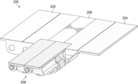
  • FIGS. 2 A- 2 D several views are shown of a hinge 200 .
  • FIG. 2 A provides a side view of hinge 200 in a flat configuration.
  • FIG. 2 B provides a side view of hinge 200 in a folded configuration.
  • FIG. 2 C provides a perspective view of hinge 200 in a flat configuration.
  • FIG. 2 D provides a perspective view of hinge 200 in a folded configuration.
  • Hinge 200 may include side plates 202 and 204 , which may be configured to hinge upwardly away from center plate 206 .
  • Hinge mechanism 208 (discussed in more detail below) may allow for desired amounts of separation to be created between center plate 206 and side plates 202 and 204 , respectively. These separations are visible in FIG. 2 D .
  • FIG. 3 shows an embodiment in which hinge 300 (generally similar to hinge 200 ) is attached to foldable display 315 .
  • hinge 300 generally similar to hinge 200
  • more than one such hinge 300 may be used in some embodiments.
  • two or more hinges 300 may be spaced along the fold axis to provide additional support.
  • such additional hinges may be spaced apart to allow for convenient cable routing.
  • FIGS. 4 A and 4 B perspective views are shown of hinge 400 including hinge mechanism 408 (which is generally similar to hinge mechanism 208 discussed above).
  • FIGS. 4 A and 4 B also illustrate the motions of various components of hinge mechanism 408 as hinge 400 is moved from a flat configuration to a folded configuration.
  • bracket 420 may cause leadscrew assembly 422 to translate as indicated by the illustrated arrows.
  • the translation of leadscrew assembly 422 relative to assembly 424 may cause assembly 424 to rotate.
  • the angle between leadscrew assembly 422 and assembly 424 thus may change.
  • the angle of assembly 426 is constant with respect to leadscrew assembly 422 .
  • the angle of assembly 428 is constant with respect to assembly 424 . Accordingly, the angle change between assemblies 422 and 424 is also the same as the angle change between assemblies 426 and 428 .
  • the rotation between assemblies 426 and 428 may also cause assembly 428 to translate. This translation of assembly 428 is the input for the next stage hinge 400 , as shown at FIG. 4 B .
  • step 1 assembly 428 translates.
  • the translation of assembly 428 along a leadscrew nut of assembly 430 may force assembly 430 to rotate.
  • the rotation of assembly 430 may force assembly 432 to translate. This translation is the input for the next stage of hinge 400 , if any. (For the sake of clarity and exposition, additional stages are not discussed in detail with respect to FIGS. 4 A and 4 B .)
  • the translation of assembly 428 also forces translation of assembly 434 .
  • the translation of assembly 434 causes rotation of assembly 436 .
  • step 5 the translation of assembly 434 relative to assembly 436 causes assembly 436 to rotate.
  • hinges according to this disclosure may include thread pitches and/or gear ratios and/or components sizes that are selected to provide a desired amount of expansion.
  • the leadscrew of assembly 430 may have a 2 mm outer diameter and a 2 mm thread pitch; the leadscrew of assembly 428 may have a 2 mm outer diameter and a 5.3 mm thread pitch.
  • the exact dimensions, thread pitches, and/or gear ratios may be tuned to give satisfactory results for any given foldable component.
  • a hinge according to this disclosure may include any desired number of stages.
  • FIGS. 5 A and 5 B show an embodiment with additional stages.
  • FIG. 5 A shows a side view of hinge 500 in a flat configuration.
  • FIG. 5 B shows a side view of hinge 500 in a partially folded configuration.
  • the additional stages of hinge 500 may be repeats of the previous stages (e.g., copies of the stages discussed in detail with respect to FIGS. 4 A and 4 B ).
  • embodiments may allow for precise control of every joint angle, synchronizing each joint to two others.
  • the mechanisms discussed herein may be scaled to accommodate different desired inside bend radii to work within the requirements of different types of foldable displays. As the bend radius changes, additional links/stages can be added as needed, and the ratios between angle 1 and angle 2 (shown in FIG. 5 B ) may be tuned by varying the thread pitch of the leads crews.
  • a hinge such that it will tend to remain in a given orientation (e.g., flat, folded, or partially folded) when a user places it in such orientation.
  • a given orientation e.g., flat, folded, or partially folded
  • additional friction may be desired in some embodiments.
  • FIG. 6 illustrates a detail view of a portion of hinge 600 which includes additional elements to generate friction and allow hinge 600 to maintain a desired orientation.
  • torque plates 650 may apply static and/or dynamic friction to any desired component of hinge 600 .
  • torque links 652 may apply static and/or dynamic friction to linkages between any desired components of hinge 600 .
  • FIGS. 7 A- 7 C some additional views of a hinge are shown.
  • FIG. 7 A shows a perspective view of hinge 700 in a flat (or open) position.
  • FIG. 7 B shows a perspective view of hinge 700 in partially folded position.
  • FIG. 7 C shows a perspective view of hinge 700 in a folded (or closed) position.
  • Hinge 700 may be generally similar in construction to the hinges discussed above, and so for the sake of brevity, its components and their various relationships are not discussed in detail with respect to FIGS. 7 A- 7 C .
  • references in the appended claims to an apparatus or system or a component of an apparatus or system being adapted to, arranged to, capable of, configured to, enabled to, operable to, or operative to perform a particular function encompasses that apparatus, system, or component, whether or not it or that particular function is activated, turned on, or unlocked, as long as that apparatus, system, or component is so adapted, arranged, capable, configured, enabled, operable, or operative.

Landscapes

  • Engineering & Computer Science (AREA)
  • Computer Hardware Design (AREA)
  • Theoretical Computer Science (AREA)
  • Physics & Mathematics (AREA)
  • Human Computer Interaction (AREA)
  • General Engineering & Computer Science (AREA)
  • General Physics & Mathematics (AREA)
  • Mathematical Physics (AREA)
  • Devices For Indicating Variable Information By Combining Individual Elements (AREA)

Abstract

A hinge apparatus may include a plurality of plates configured to be rigidly coupled to a foldable component, and a plurality of gears mechanically coupling the plurality of plates to one another. The hinge apparatus may be operable to expand such that, when the hinge apparatus transitions from a flat state to a folded state, the plurality of gears are configured to cause the plurality of plates to translate laterally apart from one another at a selected rate.

Description

TECHNICAL FIELD
The present disclosure relates in general to information handling systems, and more particularly to a hinge for foldable devices.
BACKGROUND
As the value and use of information continues to increase, individuals and businesses seek additional ways to process and store information. One option available to users is information handling systems. An information handling system generally processes, compiles, stores, and/or communicates information or data for business, personal, or other purposes thereby allowing users to take advantage of the value of the information. Because technology and information handling needs and requirements vary between different users or applications, information handling systems may also vary regarding what information is handled, how the information is handled, how much information is processed, stored, or communicated, and how quickly and efficiently the information may be processed, stored, or communicated. The variations in information handling systems allow for information handling systems to be general or configured for a specific user or specific use such as financial transaction processing, airline reservations, enterprise data storage, or global communications. In addition, information handling systems may include a variety of hardware and software components that may be configured to process, store, and communicate information and may include one or more computer systems, data storage systems, and networking systems.
Increasingly, information handling systems may include foldable components such as foldable displays. For example, phones, tablets, laptops, and other systems may include foldable organic light emitting diode (OLED) display panels that allow for large screens in a small form factor. Throughout this disclosure, the specific example of a foldable display panel is discussed for the sake of concreteness. One of ordinary skill in the art with the benefit of this disclosure will understand its applicability to other foldable components, however.
Foldable display panels are susceptible to damage during cycling of the folding mechanism, which may be caused by internal and external stresses. The front of such display panels may also be highly glossy; accordingly, any defects such as waviness, steps, gaps, etc. are likely to be easily noticed by users.
Therefore, techniques are needed for repeatably bending a foldable component in a controlled fashion for optimal performance and component life. Although this may be achieved in some embodiments by having the foldable display not fully supported by a hinge mechanism, such a solution may not provide sufficient structural support, cause problems for example when a user uses a stylus on the display. Accordingly, fully supporting a display against a backplate is desirable.
The hinges disclosed herein may solve these challenges with a multi-segment design that provides support for the panel in several locations over the full range of motion. In particular, hinge mechanisms according to this disclosure may expand at the correct rate to keep the OLED panel from experiencing tension or compression at the fold axis. In some embodiments, this expansion may occur at a selected rate (e.g., causing a particular lateral expansion distance per angular degree of folding). For example, in some embodiments, the hinge may be able to attain a flat state without gaps, in which the segments are not laterally spaced apart. As the hinge is folded, gaps may be created between the segments and may grow at a desired rate. In some embodiments, this may allow for the length of the panel to remain constant during bending, such that the hinge expands at the correct rate to allow that to happen.
It should be noted that the discussion of a technique in the Background section of this disclosure does not constitute an admission of prior-art status. No such admissions are made herein, unless clearly and unambiguously identified as such.
SUMMARY
In accordance with the teachings of the present disclosure, the disadvantages and problems associated with hinges for foldable devices may be reduced or eliminated.
In accordance with embodiments of the present disclosure, a hinge apparatus may include a plurality of plates configured to be rigidly coupled to a foldable component, and a plurality of gears mechanically coupling the plurality of plates to one another. The hinge apparatus may be operable to expand such that, when the hinge apparatus transitions from a flat state to a folded state, the plurality of gears are configured to cause the plurality of plates to translate laterally apart from one another at a selected rate.
In accordance with these and other embodiments of the present disclosure, a method may include coupling a plurality of plates to one another via a plurality of gears to create a hinge apparatus; and rigidly coupling the plurality of plates to a foldable component. The hinge apparatus may be operable to expand such that, when the hinge apparatus transitions from a flat state to a folded state, the plurality of gears are configured to cause the plurality of plates to translate laterally apart from one another at a selected rate.
In accordance with these and other embodiments of the present disclosure, an information handling system may include a foldable display panel and a hinge apparatus rigidly coupled to the foldable display panel. The hinge apparatus may include a plurality of plates and a plurality of gears mechanically coupling the plurality of plates to one another. The hinge apparatus may be operable to expand such that, when the hinge apparatus transitions from a flat state to a folded state, the plurality of gears are configured to cause the plurality of plates to translate laterally apart from one another at a selected rate.
Technical advantages of the present disclosure may be readily apparent to one skilled in the art from the figures, description and claims included herein. The objects and advantages of the embodiments will be realized and achieved at least by the elements, features, and combinations particularly pointed out in the claims.
It is to be understood that both the foregoing general description and the following detailed description are examples and explanatory and are not restrictive of the claims set forth in this disclosure.
BRIEF DESCRIPTION OF THE DRAWINGS
A more complete understanding of the present embodiments and advantages thereof may be acquired by referring to the following description taken in conjunction with the accompanying drawings, in which like reference numbers indicate like features, and wherein:
FIG. 1 illustrates a block diagram of an example information handling system, in accordance with embodiments of the present disclosure;
FIGS. 2A-2D illustrate several views of a hinge, in accordance with embodiments of the present disclosure;
FIG. 3 illustrates a hinge attached to a display panel, in accordance with embodiments of the present disclosure;
FIGS. 4A and 4B illustrate the mechanism of operation of a hinge, in accordance with embodiments of the present disclosure;
FIGS. 5A and 5B illustrate views of a hinge, in accordance with embodiments of the present disclosure;
FIG. 6 illustrates a hinge with additional friction components, in accordance with embodiments of the present disclosure; and
FIGS. 7A-7C illustrate several views of a hinge, in accordance with embodiments of the present disclosure.
DETAILED DESCRIPTION
Preferred embodiments and their advantages are best understood by reference to FIGS. 1 through 7C, wherein like numbers are used to indicate like and corresponding parts.
For the purposes of this disclosure, the term “information handling system” may include any instrumentality or aggregate of instrumentalities operable to compute, classify, process, transmit, receive, retrieve, originate, switch, store, display, manifest, detect, record, reproduce, handle, or utilize any form of information, intelligence, or data for business, scientific, control, entertainment, or other purposes. For example, an information handling system may be a personal computer, a personal digital assistant (PDA), a consumer electronic device, a network storage device, or any other suitable device and may vary in size, shape, performance, functionality, and price. The information handling system may include memory, one or more processing resources such as a central processing unit (“CPU”) or hardware or software control logic. Additional components of the information handling system may include one or more storage devices, one or more communications ports for communicating with external devices as well as various input/output (“I/O”) devices, such as a keyboard, a mouse, and a video display. The information handling system may also include one or more buses operable to transmit communication between the various hardware components.
For purposes of this disclosure, when two or more elements are referred to as “coupled” to one another, such term indicates that such two or more elements are in electronic communication or mechanical communication, as applicable, whether connected directly or indirectly, with or without intervening elements.
When two or more elements are referred to as “coupleable” to one another, such term indicates that they are capable of being coupled together.
For the purposes of this disclosure, the term “computer-readable medium” (e.g., transitory or non-transitory computer-readable medium) may include any instrumentality or aggregation of instrumentalities that may retain data and/or instructions for a period of time. Computer-readable media may include, without limitation, storage media such as a direct access storage device (e.g., a hard disk drive or floppy disk), a sequential access storage device (e.g., a tape disk drive), compact disk, CD-ROM, DVD, random access memory (RAM), read-only memory (ROM), electrically erasable programmable read-only memory (EEPROM), and/or flash memory; communications media such as wires, optical fibers, microwaves, radio waves, and other electromagnetic and/or optical carriers; and/or any combination of the foregoing.
For the purposes of this disclosure, the term “information handling resource” may broadly refer to any component system, device, or apparatus of an information handling system, including without limitation processors, service processors, basic input/output systems, buses, memories, I/O devices and/or interfaces, storage resources, network interfaces, motherboards, and/or any other components and/or elements of an information handling system.
FIG. 1 illustrates a block diagram of an example information handling system 102, in accordance with embodiments of the present disclosure. In some embodiments, information handling system 102 may comprise a server chassis configured to house a plurality of servers or “blades.” In other embodiments, information handling system 102 may comprise a personal computer (e.g., a desktop computer, laptop computer, mobile computer, and/or notebook computer). In yet other embodiments, information handling system 102 may comprise a storage enclosure configured to house a plurality of physical disk drives and/or other computer-readable media for storing data (which may generally be referred to as “physical storage resources”). As shown in FIG. 1 , information handling system 102 may comprise a processor 103, a memory 104 communicatively coupled to processor 103, a BIOS 105 (e.g., a UEFI BIOS) communicatively coupled to processor 103, a network interface 108 communicatively coupled to processor 103. In addition to the elements explicitly shown and described, information handling system 102 may include one or more other information handling resources.
Processor 103 may include any system, device, or apparatus configured to interpret and/or execute program instructions and/or process data, and may include, without limitation, a microprocessor, microcontroller, digital signal processor (DSP), application specific integrated circuit (ASIC), or any other digital or analog circuitry configured to interpret and/or execute program instructions and/or process data. In some embodiments, processor 103 may interpret and/or execute program instructions and/or process data stored in memory 104 and/or another component of information handling system 102.
Memory 104 may be communicatively coupled to processor 103 and may include any system, device, or apparatus configured to retain program instructions and/or data for a period of time (e.g., computer-readable media). Memory 104 may include RAM, EEPROM, a PCMCIA card, flash memory, magnetic storage, opto-magnetic storage, or any suitable selection and/or array of volatile or non-volatile memory that retains data after power to information handling system 102 is turned off.
As shown in FIG. 1 , memory 104 may have stored thereon an operating system 106. Operating system 106 may comprise any program of executable instructions (or aggregation of programs of executable instructions) configured to manage and/or control the allocation and usage of hardware resources such as memory, processor time, disk space, and input and output devices, and provide an interface between such hardware resources and application programs hosted by operating system 106. In addition, operating system 106 may include all or a portion of a network stack for network communication via a network interface (e.g., network interface 108 for communication over a data network). Although operating system 106 is shown in FIG. 1 as stored in memory 104, in some embodiments operating system 106 may be stored in storage media accessible to processor 103, and active portions of operating system 106 may be transferred from such storage media to memory 104 for execution by processor 103.
Network interface 108 may comprise one or more suitable systems, apparatuses, or devices operable to serve as an interface between information handling system 102 and one or more other information handling systems via an in-band network. Network interface 108 may enable information handling system 102 to communicate using any suitable transmission protocol and/or standard. In these and other embodiments, network interface 108 may comprise a network interface card, or “NIC.” In these and other embodiments, network interface 108 may be enabled as a local area network (LAN)-on-motherboard (LOM) card.
Information handling system 102 may further include a foldable component such as foldable display 115. As discussed above, if foldable display were attached to a standard hinge to allow such folding, then foldable display 115 would experience compression and/or shear forces due to its non-zero thickness (e.g., due to the distance between the hinge and the front face of foldable display 115). Accordingly, it is desirable to be able to fold foldable display 115 in such a way that it does not experience any such compression or shear forces.
Some embodiments of this disclosure may achieve the desired motion by employing selected gear ratios between various components of an expandable hinge. A series of rotations and translations between parts may constrain the motion of all joints to produce repeatable, controlled motion, allowing the hinge to expand by the amount needed to prevent foldable display 115 from experiencing compression or shear (or tension) forces.
Different gear ratios may be used in different embodiments, because the exact expansion characteristics that are desired may vary from one type of foldable display to another. Leadscrews may advantageously be used in some embodiments, because they provide a way to fine tune a gear ratio without modifying the diameter of the gear (with spur gears, for example, the diameter of the gear would change when the gear ratio changed). Thus different expansion characteristics may be created as desired by changing gear ratios, without the need to completely redesign a hinge. For purposes of this disclosure, the general term “gears” may be understood to refer to leadscrews, leadscrew nuts, spur gears, and other types of gears.
Turning now to FIGS. 2A-2D, several views are shown of a hinge 200. FIG. 2A provides a side view of hinge 200 in a flat configuration. FIG. 2B provides a side view of hinge 200 in a folded configuration. FIG. 2C provides a perspective view of hinge 200 in a flat configuration. FIG. 2D provides a perspective view of hinge 200 in a folded configuration.
Hinge 200 may include side plates 202 and 204, which may be configured to hinge upwardly away from center plate 206. Hinge mechanism 208 (discussed in more detail below) may allow for desired amounts of separation to be created between center plate 206 and side plates 202 and 204, respectively. These separations are visible in FIG. 2D.
FIG. 3 shows an embodiment in which hinge 300 (generally similar to hinge 200) is attached to foldable display 315. Depending on the size and shape of foldable display 315, as well as the desired overall dimensions of a device including display 315, more than one such hinge 300 may be used in some embodiments. For example, in embodiments in which the fold axis is long relative to the size of hinge 300, two or more hinges 300 may be spaced along the fold axis to provide additional support. In some embodiments, such additional hinges may be spaced apart to allow for convenient cable routing.
Turning now to FIGS. 4A and 4B, perspective views are shown of hinge 400 including hinge mechanism 408 (which is generally similar to hinge mechanism 208 discussed above). FIGS. 4A and 4B also illustrate the motions of various components of hinge mechanism 408 as hinge 400 is moved from a flat configuration to a folded configuration.
The gear relationships described with respect to FIGS. 4A and 4B may create a loop of influence between all axes. To facilitate understanding of the relationships between components, the movement of hinge 400 will be discussed in stages, but in practice, the movements of all stages may occur simultaneously to control all degrees of freedom and provide predictable motion.
As shown at step 1 of FIG. 4A, as hinge 400 begins to fold, the rotation of bracket 420 may cause leadscrew assembly 422 to translate as indicated by the illustrated arrows.
At step 2, the translation of leadscrew assembly 422 relative to assembly 424 may cause assembly 424 to rotate. The angle between leadscrew assembly 422 and assembly 424 thus may change.
As shown at step 3, the angle of assembly 426 is constant with respect to leadscrew assembly 422. The angle of assembly 428 is constant with respect to assembly 424. Accordingly, the angle change between assemblies 422 and 424 is also the same as the angle change between assemblies 426 and 428.
At step 4, the rotation between assemblies 426 and 428 may also cause assembly 428 to translate. This translation of assembly 428 is the input for the next stage hinge 400, as shown at FIG. 4B.
Turning now to FIG. 4B, at step 1, assembly 428 translates.
At step 2, the translation of assembly 428 along a leadscrew nut of assembly 430 may force assembly 430 to rotate.
At step 3, the rotation of assembly 430 may force assembly 432 to translate. This translation is the input for the next stage of hinge 400, if any. (For the sake of clarity and exposition, additional stages are not discussed in detail with respect to FIGS. 4A and 4B.)
As shown at step 4, the translation of assembly 428 also forces translation of assembly 434. The translation of assembly 434 causes rotation of assembly 436.
At step 5, the translation of assembly 434 relative to assembly 436 causes assembly 436 to rotate.
As noted above, hinges according to this disclosure may include thread pitches and/or gear ratios and/or components sizes that are selected to provide a desired amount of expansion. As one example that has been found to give satisfactory results with a particular type of foldable display panel, the leadscrew of assembly 430 may have a 2 mm outer diameter and a 2 mm thread pitch; the leadscrew of assembly 428 may have a 2 mm outer diameter and a 5.3 mm thread pitch. However, the exact dimensions, thread pitches, and/or gear ratios may be tuned to give satisfactory results for any given foldable component.
As noted above, in some embodiments, a hinge according to this disclosure may include any desired number of stages. FIGS. 5A and 5B show an embodiment with additional stages.
FIG. 5A shows a side view of hinge 500 in a flat configuration. FIG. 5B shows a side view of hinge 500 in a partially folded configuration.
In particular, the additional stages of hinge 500 may be repeats of the previous stages (e.g., copies of the stages discussed in detail with respect to FIGS. 4A and 4B). Thus embodiments may allow for precise control of every joint angle, synchronizing each joint to two others.
The mechanisms discussed herein may be scaled to accommodate different desired inside bend radii to work within the requirements of different types of foldable displays. As the bend radius changes, additional links/stages can be added as needed, and the ratios between angle 1 and angle 2 (shown in FIG. 5B) may be tuned by varying the thread pitch of the leads crews.
In some embodiments, it may also be desirable to construct a hinge such that it will tend to remain in a given orientation (e.g., flat, folded, or partially folded) when a user places it in such orientation. Although the interactions between the various components discussed above with respect to FIGS. 4A and 4B may provide some friction, additional friction may be desired in some embodiments.
Accordingly, FIG. 6 illustrates a detail view of a portion of hinge 600 which includes additional elements to generate friction and allow hinge 600 to maintain a desired orientation. As shown, torque plates 650 may apply static and/or dynamic friction to any desired component of hinge 600. In these and other embodiments, torque links 652 may apply static and/or dynamic friction to linkages between any desired components of hinge 600.
Turning now to FIGS. 7A-7C, some additional views of a hinge are shown. FIG. 7A shows a perspective view of hinge 700 in a flat (or open) position. FIG. 7B shows a perspective view of hinge 700 in partially folded position. FIG. 7C shows a perspective view of hinge 700 in a folded (or closed) position. Hinge 700 may be generally similar in construction to the hinges discussed above, and so for the sake of brevity, its components and their various relationships are not discussed in detail with respect to FIGS. 7A-7C.
Although various possible advantages with respect to embodiments of this disclosure have been described, one of ordinary skill in the art with the benefit of this disclosure will understand that in any particular embodiment, not all of such advantages may be applicable. In any particular embodiment, some, all, or even none of the listed advantages may apply.
This disclosure encompasses all changes, substitutions, variations, alterations, and modifications to the exemplary embodiments herein that a person having ordinary skill in the art would comprehend. Similarly, where appropriate, the appended claims encompass all changes, substitutions, variations, alterations, and modifications to the exemplary embodiments herein that a person having ordinary skill in the art would comprehend. Moreover, reference in the appended claims to an apparatus or system or a component of an apparatus or system being adapted to, arranged to, capable of, configured to, enabled to, operable to, or operative to perform a particular function encompasses that apparatus, system, or component, whether or not it or that particular function is activated, turned on, or unlocked, as long as that apparatus, system, or component is so adapted, arranged, capable, configured, enabled, operable, or operative.
Unless otherwise specifically noted, articles depicted in the drawings are not necessarily drawn to scale. However, in some embodiments, articles depicted in the drawings may be to scale.
Further, reciting in the appended claims that a structure is “configured to” or “operable to” perform one or more tasks is expressly intended not to invoke 35 U.S.C. § 112(f) for that claim element. Accordingly, none of the claims in this application as filed are intended to be interpreted as having means-plus-function elements. Should Applicant wish to invoke § 112(f) during prosecution, Applicant will recite claim elements using the “means for [performing a function]” construct.
All examples and conditional language recited herein are intended for pedagogical objects to aid the reader in understanding the invention and the concepts contributed by the inventor to furthering the art, and are construed as being without limitation to such specifically recited examples and conditions. Although embodiments of the present inventions have been described in detail, it should be understood that various changes, substitutions, and alterations could be made hereto without departing from the spirit and scope of the disclosure.

Claims (18)

What is claimed is:
1. A hinge apparatus comprising:
a plurality of plates configured to be rigidly coupled to a foldable component; and
a plurality of gears mechanically coupling the plurality of plates to one another;
wherein the hinge apparatus is operable to expand such that, when the hinge apparatus transitions from a flat state to a folded state, the plurality of gears are configured to cause the plurality of plates to translate laterally apart from one another at a selected rate; and
wherein, when the hinge apparatus is in the flat state, the plurality of plates are in contact with one another, without gaps therebetween.
2. The hinge apparatus of claim 1, wherein the foldable component is a display panel.
3. The hinge apparatus of claim 2, wherein the display panel is an organic light emitting diode (OLED) display panel.
4. The hinge apparatus of claim 1, wherein the plurality of plates includes a center plate configured to be aligned along a fold axis of the foldable component.
5. The hinge apparatus of claim 4, wherein the plurality of plates further includes two side plates laterally displaced from the center plate.
6. The hinge apparatus of claim 1, wherein the hinge apparatus is further operable to contract such that, when the hinge apparatus transitions from the folded state to the flat state, the plurality of gears are configured to cause the plurality of plates to translate laterally together toward one another at the selected rate.
7. The hinge apparatus of claim 1, wherein the selected rate is selected such that when the plurality of plates are rigidly coupled to a back surface of a particular foldable component and when the hinge apparatus transitions from the flat state to the folded state, a front surface of the foldable component experiences no compression or tension forces.
8. A method comprising:
coupling a plurality of plates to one another via a plurality of gears to create a hinge apparatus; and
rigidly coupling the plurality of plates to a foldable component;
wherein the hinge apparatus is operable to expand such that, when the hinge apparatus transitions from a flat state to a folded state, the plurality of gears are configured to cause the plurality of plates to translate laterally apart from one another at a selected rate; and
wherein, when the hinge apparatus is in the flat state, the plurality of plates are in contact with one another, without gaps therebetween.
9. The method of claim 8, further comprising: coupling a friction-generating component to at least one of the plurality of gears.
10. The method of claim 9, wherein the friction-generating component is configured to generate sufficient friction to maintain the hinge apparatus in a particular orientation.
11. The method of claim 8, wherein the plurality of gears includes a plurality of leadscrews.
12. An information handling system comprising:
a foldable display panel;
a hinge apparatus rigidly coupled to the foldable display panel;
wherein the hinge apparatus includes:
a plurality of plates; and
a plurality of gears mechanically coupling the plurality of plates to one another;
wherein the hinge apparatus is operable to expand such that, when the hinge apparatus transitions from a flat state to a folded state, the plurality of gears are configured to cause the plurality of plates to translate laterally apart from one another at a selected rate; and
wherein, when the hinge apparatus is in the flat state, the plurality of plates are in contact with one another, without gaps therebetween.
13. The information handling system of claim 12, wherein the plurality of gears includes a plurality of leadscrews and a plurality of leadscrew nuts.
14. The information handling system of claim 13, wherein the display panel is an organic light emitting diode (OLED) display panel.
15. The information handling system of claim 12, wherein the plurality of plates includes a center plate configured to be aligned along a fold axis of the foldable display panel.
16. The information handling system of claim 15, wherein the plurality of plates further includes two side plates laterally displaced from the center plate.
17. The information handling system of claim 12, wherein the hinge apparatus is further operable to contract such that, when the hinge apparatus transitions from the folded state to the flat state, the plurality of gears are configured to cause the plurality of plates to translate laterally together toward one another at the selected rate.
18. The information handling system of claim 12, wherein the selected rate is selected such that when the hinge apparatus transitions from the flat state to the folded state, a front surface of the foldable display panel experiences no compression or tension forces.
US17/159,880 2021-01-27 2021-01-27 Synchronous multi-segment hinge for foldable devices Active 2041-08-23 US11650632B2 (en)

Priority Applications (1)

Application Number Priority Date Filing Date Title
US17/159,880 US11650632B2 (en) 2021-01-27 2021-01-27 Synchronous multi-segment hinge for foldable devices

Applications Claiming Priority (1)

Application Number Priority Date Filing Date Title
US17/159,880 US11650632B2 (en) 2021-01-27 2021-01-27 Synchronous multi-segment hinge for foldable devices

Publications (2)

Publication Number Publication Date
US20220236772A1 US20220236772A1 (en) 2022-07-28
US11650632B2 true US11650632B2 (en) 2023-05-16

Family

ID=82495509

Family Applications (1)

Application Number Title Priority Date Filing Date
US17/159,880 Active 2041-08-23 US11650632B2 (en) 2021-01-27 2021-01-27 Synchronous multi-segment hinge for foldable devices

Country Status (1)

Country Link
US (1) US11650632B2 (en)

Families Citing this family (1)

* Cited by examiner, † Cited by third party
Publication number Priority date Publication date Assignee Title
WO2025165373A1 (en) * 2024-02-02 2025-08-07 Google Llc Folding portable display device with leadscrews

Citations (5)

* Cited by examiner, † Cited by third party
Publication number Priority date Publication date Assignee Title
US20100232100A1 (en) * 2009-03-16 2010-09-16 Yohei Fukuma Electronic Apparatus
US20170328102A1 (en) * 2016-05-12 2017-11-16 Kem Hongkong Limited Triaxial Hinge and Electronic Device Using the Same
US20190146559A1 (en) * 2017-11-13 2019-05-16 Fositek Corporation Torsion device and electronic apparatus
US10480225B1 (en) * 2018-12-25 2019-11-19 Fositek Corporation Hinge mechanism and flexible electronic device having the same
US10664021B1 (en) * 2019-06-25 2020-05-26 Fositek Corporation Foldable display device and a hinge mechanism

Patent Citations (5)

* Cited by examiner, † Cited by third party
Publication number Priority date Publication date Assignee Title
US20100232100A1 (en) * 2009-03-16 2010-09-16 Yohei Fukuma Electronic Apparatus
US20170328102A1 (en) * 2016-05-12 2017-11-16 Kem Hongkong Limited Triaxial Hinge and Electronic Device Using the Same
US20190146559A1 (en) * 2017-11-13 2019-05-16 Fositek Corporation Torsion device and electronic apparatus
US10480225B1 (en) * 2018-12-25 2019-11-19 Fositek Corporation Hinge mechanism and flexible electronic device having the same
US10664021B1 (en) * 2019-06-25 2020-05-26 Fositek Corporation Foldable display device and a hinge mechanism

Also Published As

Publication number Publication date
US20220236772A1 (en) 2022-07-28

Similar Documents

Publication Publication Date Title
US11576272B2 (en) Electronic device including flexible display
US20150309539A1 (en) Information Handling System Housing Synchronization with Differential Torque Hinge
US8879250B2 (en) Tablet support system
US11656659B2 (en) Portable information handling system hinge with hybrid rotation for distributed torque
US10563438B1 (en) Hinge device with helical gear
US10019040B2 (en) Convertible device hinge cable routing system
US20230064740A1 (en) High-density co-packaged optics networking system
US10203731B1 (en) Semi-solid hinge cover
US20180095504A1 (en) Systems and methods for mechanically interfacing camera to hinge of information handling system
US20170255231A1 (en) Information Handling System Low Profile Hinge
US11650632B2 (en) Synchronous multi-segment hinge for foldable devices
US20100001148A1 (en) Flat Panel Monitor Assembly with Weight Adjust Mechanism
US12476987B2 (en) Datacenter secure control module (DC-SCM) as-a-service system
US9910459B2 (en) Thermal insulator and radiation shield
US8144463B2 (en) Card retention system
US10310556B2 (en) Information handling system multi-torque dual axis hinge
US7643303B1 (en) Rotating and translating control panel
US20240385861A1 (en) Emulated device management system
US20070091549A1 (en) Method and apparatus for mounting a component in a chassis
CN105511549A (en) Electronic device
US11003223B2 (en) Cable retention mechanism
US12147275B2 (en) Seamless dual screen hinge
US20240260223A1 (en) Multi-shelf mounting solution
US20250238250A1 (en) Systems and methods for independent container layer sharing in a distributed ecosystem
US9883605B2 (en) Rack attic device coupling system

Legal Events

Date Code Title Description
AS Assignment

Owner name: DELL PRODUCTS L.P., TEXAS

Free format text: ASSIGNMENT OF ASSIGNORS INTEREST;ASSIGNORS:MORRISON, JIM;TORRES, CHRIS;SIGNING DATES FROM 20210121 TO 20210125;REEL/FRAME:055051/0156

FEPP Fee payment procedure

Free format text: ENTITY STATUS SET TO UNDISCOUNTED (ORIGINAL EVENT CODE: BIG.); ENTITY STATUS OF PATENT OWNER: LARGE ENTITY

AS Assignment

Owner name: CREDIT SUISSE AG, CAYMAN ISLANDS BRANCH, NORTH CAROLINA

Free format text: SECURITY AGREEMENT;ASSIGNORS:EMC IP HOLDING COMPANY LLC;DELL PRODUCTS L.P.;REEL/FRAME:055408/0697

Effective date: 20210225

AS Assignment

Owner name: THE BANK OF NEW YORK MELLON TRUST COMPANY, N.A., AS NOTES COLLATERAL AGENT, TEXAS

Free format text: SECURITY INTEREST;ASSIGNORS:EMC IP HOLDING COMPANY LLC;DELL PRODUCTS L.P.;REEL/FRAME:055479/0342

Effective date: 20210225

Owner name: THE BANK OF NEW YORK MELLON TRUST COMPANY, N.A., AS NOTES COLLATERAL AGENT, TEXAS

Free format text: SECURITY INTEREST;ASSIGNORS:EMC IP HOLDING COMPANY LLC;DELL PRODUCTS L.P.;REEL/FRAME:055479/0051

Effective date: 20210225

Owner name: THE BANK OF NEW YORK MELLON TRUST COMPANY, N.A., AS NOTES COLLATERAL AGENT, TEXAS

Free format text: SECURITY INTEREST;ASSIGNORS:EMC IP HOLDING COMPANY LLC;DELL PRODUCTS L.P.;REEL/FRAME:056136/0752

Effective date: 20210225

AS Assignment

Owner name: EMC IP HOLDING COMPANY LLC, TEXAS

Free format text: RELEASE OF SECURITY INTEREST AT REEL 055408 FRAME 0697;ASSIGNOR:CREDIT SUISSE AG, CAYMAN ISLANDS BRANCH;REEL/FRAME:058001/0553

Effective date: 20211101

Owner name: DELL PRODUCTS L.P., TEXAS

Free format text: RELEASE OF SECURITY INTEREST AT REEL 055408 FRAME 0697;ASSIGNOR:CREDIT SUISSE AG, CAYMAN ISLANDS BRANCH;REEL/FRAME:058001/0553

Effective date: 20211101

AS Assignment

Owner name: DELL PRODUCTS L.P., TEXAS

Free format text: RELEASE OF SECURITY INTEREST IN PATENTS PREVIOUSLY RECORDED AT REEL/FRAME (056136/0752);ASSIGNOR:THE BANK OF NEW YORK MELLON TRUST COMPANY, N.A., AS NOTES COLLATERAL AGENT;REEL/FRAME:062021/0771

Effective date: 20220329

Owner name: EMC IP HOLDING COMPANY LLC, TEXAS

Free format text: RELEASE OF SECURITY INTEREST IN PATENTS PREVIOUSLY RECORDED AT REEL/FRAME (056136/0752);ASSIGNOR:THE BANK OF NEW YORK MELLON TRUST COMPANY, N.A., AS NOTES COLLATERAL AGENT;REEL/FRAME:062021/0771

Effective date: 20220329

Owner name: DELL PRODUCTS L.P., TEXAS

Free format text: RELEASE OF SECURITY INTEREST IN PATENTS PREVIOUSLY RECORDED AT REEL/FRAME (055479/0051);ASSIGNOR:THE BANK OF NEW YORK MELLON TRUST COMPANY, N.A., AS NOTES COLLATERAL AGENT;REEL/FRAME:062021/0663

Effective date: 20220329

Owner name: EMC IP HOLDING COMPANY LLC, TEXAS

Free format text: RELEASE OF SECURITY INTEREST IN PATENTS PREVIOUSLY RECORDED AT REEL/FRAME (055479/0051);ASSIGNOR:THE BANK OF NEW YORK MELLON TRUST COMPANY, N.A., AS NOTES COLLATERAL AGENT;REEL/FRAME:062021/0663

Effective date: 20220329

Owner name: DELL PRODUCTS L.P., TEXAS

Free format text: RELEASE OF SECURITY INTEREST IN PATENTS PREVIOUSLY RECORDED AT REEL/FRAME (055479/0342);ASSIGNOR:THE BANK OF NEW YORK MELLON TRUST COMPANY, N.A., AS NOTES COLLATERAL AGENT;REEL/FRAME:062021/0460

Effective date: 20220329

Owner name: EMC IP HOLDING COMPANY LLC, TEXAS

Free format text: RELEASE OF SECURITY INTEREST IN PATENTS PREVIOUSLY RECORDED AT REEL/FRAME (055479/0342);ASSIGNOR:THE BANK OF NEW YORK MELLON TRUST COMPANY, N.A., AS NOTES COLLATERAL AGENT;REEL/FRAME:062021/0460

Effective date: 20220329

STPP Information on status: patent application and granting procedure in general

Free format text: NON FINAL ACTION MAILED

AS Assignment

Owner name: DELL PRODUCTS L.P., TEXAS

Free format text: CORRECT ERROR IN PREVIOUSLY RECORDED COVER SHEET, REEL 055051 AND FRAME 0156, CORRECTION TO THE SPELLING OF ASSIGNOR'S NAME;ASSIGNORS:MORRISON, JASON;TORRES, CHRIS;SIGNING DATES FROM 20210121 TO 20210125;REEL/FRAME:063214/0026

STCF Information on status: patent grant

Free format text: PATENTED CASE