US11650146B2 - Specimen inspection machine and operation method thereof - Google Patents
Specimen inspection machine and operation method thereof Download PDFInfo
- Publication number
- US11650146B2 US11650146B2 US16/853,873 US202016853873A US11650146B2 US 11650146 B2 US11650146 B2 US 11650146B2 US 202016853873 A US202016853873 A US 202016853873A US 11650146 B2 US11650146 B2 US 11650146B2
- Authority
- US
- United States
- Prior art keywords
- inspection
- accommodating grooves
- sensing signals
- specimen
- liquid surface
- Prior art date
- Legal status (The legal status is an assumption and is not a legal conclusion. Google has not performed a legal analysis and makes no representation as to the accuracy of the status listed.)
- Active, expires
Links
- 238000007689 inspection Methods 0.000 title claims abstract description 227
- 238000000034 method Methods 0.000 title claims description 53
- 239000007788 liquid Substances 0.000 claims description 47
- 239000012530 fluid Substances 0.000 claims description 25
- 238000002347 injection Methods 0.000 claims description 16
- 239000007924 injection Substances 0.000 claims description 16
- 239000011324 bead Substances 0.000 claims description 14
- 230000002159 abnormal effect Effects 0.000 claims description 12
- 102000053602 DNA Human genes 0.000 description 3
- 108020004414 DNA Proteins 0.000 description 3
- 238000012986 modification Methods 0.000 description 2
- 230000004048 modification Effects 0.000 description 2
- 238000005406 washing Methods 0.000 description 2
- 239000008280 blood Substances 0.000 description 1
- 210000004369 blood Anatomy 0.000 description 1
- 230000000694 effects Effects 0.000 description 1
- 238000000605 extraction Methods 0.000 description 1
- 210000003296 saliva Anatomy 0.000 description 1
- 150000003839 salts Chemical class 0.000 description 1
- 239000000243 solution Substances 0.000 description 1
Images


Classifications
-
- G—PHYSICS
- G01—MEASURING; TESTING
- G01N—INVESTIGATING OR ANALYSING MATERIALS BY DETERMINING THEIR CHEMICAL OR PHYSICAL PROPERTIES
- G01N21/00—Investigating or analysing materials by the use of optical means, i.e. using sub-millimetre waves, infrared, visible or ultraviolet light
- G01N21/17—Systems in which incident light is modified in accordance with the properties of the material investigated
- G01N21/25—Colour; Spectral properties, i.e. comparison of effect of material on the light at two or more different wavelengths or wavelength bands
- G01N21/31—Investigating relative effect of material at wavelengths characteristic of specific elements or molecules, e.g. atomic absorption spectrometry
- G01N21/35—Investigating relative effect of material at wavelengths characteristic of specific elements or molecules, e.g. atomic absorption spectrometry using infrared light
-
- G—PHYSICS
- G01—MEASURING; TESTING
- G01N—INVESTIGATING OR ANALYSING MATERIALS BY DETERMINING THEIR CHEMICAL OR PHYSICAL PROPERTIES
- G01N21/00—Investigating or analysing materials by the use of optical means, i.e. using sub-millimetre waves, infrared, visible or ultraviolet light
- G01N21/17—Systems in which incident light is modified in accordance with the properties of the material investigated
- G01N21/25—Colour; Spectral properties, i.e. comparison of effect of material on the light at two or more different wavelengths or wavelength bands
- G01N21/251—Colorimeters; Construction thereof
- G01N21/253—Colorimeters; Construction thereof for batch operation, i.e. multisample apparatus
-
- G—PHYSICS
- G01—MEASURING; TESTING
- G01N—INVESTIGATING OR ANALYSING MATERIALS BY DETERMINING THEIR CHEMICAL OR PHYSICAL PROPERTIES
- G01N33/00—Investigating or analysing materials by specific methods not covered by groups G01N1/00 - G01N31/00
- G01N33/48—Biological material, e.g. blood, urine; Haemocytometers
-
- G—PHYSICS
- G01—MEASURING; TESTING
- G01N—INVESTIGATING OR ANALYSING MATERIALS BY DETERMINING THEIR CHEMICAL OR PHYSICAL PROPERTIES
- G01N21/00—Investigating or analysing materials by the use of optical means, i.e. using sub-millimetre waves, infrared, visible or ultraviolet light
- G01N21/84—Systems specially adapted for particular applications
- G01N21/88—Investigating the presence of flaws or contamination
- G01N21/8806—Specially adapted optical and illumination features
-
- G—PHYSICS
- G01—MEASURING; TESTING
- G01S—RADIO DIRECTION-FINDING; RADIO NAVIGATION; DETERMINING DISTANCE OR VELOCITY BY USE OF RADIO WAVES; LOCATING OR PRESENCE-DETECTING BY USE OF THE REFLECTION OR RERADIATION OF RADIO WAVES; ANALOGOUS ARRANGEMENTS USING OTHER WAVES
- G01S17/00—Systems using the reflection or reradiation of electromagnetic waves other than radio waves, e.g. lidar systems
- G01S17/02—Systems using the reflection of electromagnetic waves other than radio waves
- G01S17/06—Systems determining position data of a target
- G01S17/08—Systems determining position data of a target for measuring distance only
-
- G—PHYSICS
- G01—MEASURING; TESTING
- G01V—GEOPHYSICS; GRAVITATIONAL MEASUREMENTS; DETECTING MASSES OR OBJECTS; TAGS
- G01V8/00—Prospecting or detecting by optical means
- G01V8/10—Detecting, e.g. by using light barriers
-
- G—PHYSICS
- G01—MEASURING; TESTING
- G01N—INVESTIGATING OR ANALYSING MATERIALS BY DETERMINING THEIR CHEMICAL OR PHYSICAL PROPERTIES
- G01N21/00—Investigating or analysing materials by the use of optical means, i.e. using sub-millimetre waves, infrared, visible or ultraviolet light
- G01N21/84—Systems specially adapted for particular applications
- G01N21/88—Investigating the presence of flaws or contamination
- G01N21/8851—Scan or image signal processing specially adapted therefor, e.g. for scan signal adjustment, for detecting different kinds of defects, for compensating for structures, markings, edges
- G01N2021/8854—Grading and classifying of flaws
- G01N2021/8867—Grading and classifying of flaws using sequentially two or more inspection runs, e.g. coarse and fine, or detecting then analysing
-
- G—PHYSICS
- G01—MEASURING; TESTING
- G01N—INVESTIGATING OR ANALYSING MATERIALS BY DETERMINING THEIR CHEMICAL OR PHYSICAL PROPERTIES
- G01N21/00—Investigating or analysing materials by the use of optical means, i.e. using sub-millimetre waves, infrared, visible or ultraviolet light
- G01N21/17—Systems in which incident light is modified in accordance with the properties of the material investigated
- G01N21/25—Colour; Spectral properties, i.e. comparison of effect of material on the light at two or more different wavelengths or wavelength bands
- G01N21/31—Investigating relative effect of material at wavelengths characteristic of specific elements or molecules, e.g. atomic absorption spectrometry
- G01N21/35—Investigating relative effect of material at wavelengths characteristic of specific elements or molecules, e.g. atomic absorption spectrometry using infrared light
- G01N21/3563—Investigating relative effect of material at wavelengths characteristic of specific elements or molecules, e.g. atomic absorption spectrometry using infrared light for analysing solids; Preparation of samples therefor
Definitions
- An embodiment of the present invention relates to an inspection machine, and in particular it relates to a specimen inspection machine and an operation method thereof.
- the user when a user uses a specimen inspection machine to inspect a specimen, the user operates the human-machine interface provided by the specimen inspection machine to select accommodating grooves to be inspected on the inspection device, such that the specimen inspection machine inspects the specimen of the selected accommodating grooves.
- the selection of the accommodating grooves to be inspected on the inspection device is a manual operation, if the user makes a wrong selection, it may lead to the loss of the specimen and the failure of the specimen inspection process.
- the specimen inspection machine may only detect whether the inspection device is placed, but the specimen inspection machine may not confirm that the inspection device is placed properly. However, if the inspection device is not placed properly, when the specimen inspection machine performs a drainage operation, the inspection magnetic beads in the accommodating grooves may be sucked away, causing the loss of the specimen and the failure of the specimen-inspection procedure. Furthermore, the specimen inspection machine does not have a mechanism for detecting the buffer fluid injection tube. That is, when the buffer fluid injection tube is blocked, the specimen-inspection procedure may fail.
- An embodiment of the present invention provides a specimen inspection machine and an operation method thereof, thereby effectively avoiding the failure of the specimen-inspection procedure and increasing the convenience of use.
- An embodiment of the present invention provides a specimen inspection machine, which includes a case, a carrying device, an inspection device, a sensing device and a control device.
- the carrying device is disposed in the case.
- the inspection device is disposed on the carrying device.
- the inspection device has a plurality of accommodating grooves, each of the accommodating grooves is used for accommodating an inspection sample, and the inspection sample at least includes a specimen.
- the sensing device is disposed in the case and is disposed on a side of the case opposite the carrying device.
- the sensing device senses the inspection device to generate a plurality of first sensing signals and a plurality of second sensing signals.
- the control device is disposed in the case.
- the control device receives the first sensing signals and the second sensing signals.
- the control device determines whether the inspection device is disposed in the correct position according to the first sensing signals.
- the control device determines whether inspection samples are placed in the accommodating grooves according to the second sensing signals to inspect the accommodating grooves placed with
- an embodiment of the present invention provides an operation method of a specimen inspection machine, which includes the following steps.
- An inspection device is disposed on a carrying device, wherein the inspection device has a plurality of accommodating grooves, each of the accommodating grooves is used for accommodating an inspection sample, and the inspection sample at least includes a specimen.
- a sensing device is used to sense the inspection device, so as to generate a plurality of first sensing signals, wherein the sensing device is disposed opposite the carrying device.
- a control device is used to receive the first sensing signals and determine whether the inspection device is disposed in the correct position according to the first sensing signals.
- the sensing device is used to sense the inspection device, so as to generate a plurality of second sensing signals.
- the control device is used to receive the second sensing signals, determine whether inspection samples are placed in the accommodating grooves according to the second sensing signals, and inspect the accommodating grooves placed with the inspection samples.
- the sensing device senses the inspection device disposed on the carrying device to generate the first sensing signals, and the control device determines whether the inspection device is disposed in the correct position according to the first sensing signals.
- the sensing device senses the inspection device to generate the second sensing signals, and the control device determines whether inspection samples are placed in the accommodating grooves according to the second sensing signals to inspect the accommodating grooves placed with the inspection samples. Therefore, the failure of the specimen-inspection procedure may be effectively avoided, and the convenience of use is increased.
- FIG. 1 is a schematic view of a specimen inspection machine according to an embodiment of the present invention
- FIG. 2 is a schematic view of an inspection device according to an embodiment of the present invention.
- FIGS. 3 A and 3 B are a schematic view of a corresponding relationship of an accommodating groove and a plurality of magnetic elements according to an embodiment of the present invention
- FIG. 4 is a flowchart of an operation method of a specimen inspection machine according to an embodiment of the present invention.
- FIG. 5 is a detailed flowchart of step S 404 and step S 406 in FIG. 4 ;
- FIG. 6 is a detailed flowchart of step S 408 and step S 410 in FIG. 4 ;
- FIG. 7 is a flowchart of an operation method of a specimen inspection machine according to another embodiment of the present invention.
- FIG. 1 is a schematic view of a specimen inspection machine according to an embodiment of the present invention.
- the specimen inspection machine 100 is, for example, a beads washing machine, so as to inspect at least one specimen. For example, a copy, an extraction, a washing of inspecting deoxyribonucleic acid (DNA) is performed on the specimen.
- the specimen inspection machine 100 includes a case 110 , a carrying device 120 , an inspection device 130 , a sensing device 140 and a control device 150 .
- the carrying device 120 is disposed in the case 110 .
- the inspection device 130 is disposed on the carrying device 120 .
- the inspection device 130 has a plurality of accommodating grooves 131 , as shown in FIG. 2 .
- each of the accommodating grooves 131 is used for accommodating an inspection sample, wherein the inspection sample may include a specimen, a buffer fluid and a plurality of inspection magnetic beads.
- the above specimen is, for example, blood, saliva, or body tissue containing DNA.
- the buffer fluid is, for example, a solution containing salts.
- the inspection magnetic beads may be configured with inspection barcodes. The user may know the inspection state of the specimen according to the appearance of the inspection barcodes on the inspection magnetic beads.
- the user may place the specimen to be inspected and the inspection magnetic beads in the corresponding accommodating groove 131 , and inject the buffer fluids in the corresponding accommodating groove 131 .
- the inspection device 130 is placed on the carrying device 120 in the specimen inspection machine 100 , so as to inspect the inspection samples of the accommodating grooves 131 .
- the sensing device 140 is disposed in the case 110 and disposed on a side 111 of the case 110 opposite to the carrying device 120 .
- the sensing device 140 senses the inspection device 130 to generate a plurality of first sensing signals and a plurality of second sensing signals.
- the sensing device 140 is, for example, an infrared light image sensor or a digital light source image sensor, but the embodiment of the present invention is not limited thereto.
- the sensing device 140 has a function of time of flight.
- the sensing device 140 may emit an infrared light or a digital light to the inspection device 130 , and receive a reflected light generated by the inspection device 130 reflecting the infrared light or the digital light.
- the sensing device 140 may calculate a distance between the sensing device 140 and the inspection device according to an emitting time of emitting the infrared light or the digital light and a receiving time of receiving the reflected light, so as to generate the corresponding sensing signal. That is, when a difference between the emitting time and the receiving time is small, it indicates that the distance between the sensing device 140 and the inspection device 130 is short. When the difference between the emitting time and the receiving time is large, it indicates that the distance between the sensing device 140 and the inspection device 130 is long.
- the sensing device 140 senses four corners 132 , 133 , 134 and 135 (as shown in FIG. 2 ) of the inspection device 130 to generate a plurality of the first sensing signals. In addition, the sensing device 140 senses the accommodating grooves 131 of the inspection device 130 to generate a plurality of second sensing signals.
- the control device 150 is disposed in the case 110 and is coupled to the sensing device 140 .
- the position of the control device 150 is only schematic, but the disposing position of the control device 150 is not limited thereto.
- the control device 150 may be disposed on the carrying device 120 or disposed in the carrying device 120 , and the same effect may be achieved.
- the control device 150 may receive the first sensing signals and the second sensing signals generated by the sensing device 140 .
- the control device 150 may receive the first sensing signals and the second sensing signals generated by the sensing device 140 through a wired manner or a wireless manner.
- the control device 150 may determine whether the inspection device 130 is disposed in the correct position according to the first sensing signals. Furthermore, the control device 150 may determine whether image depths corresponding to the four corners 132 , 133 , 134 and 135 of the inspection device 130 are equal to a predetermined depth according to the first sensing signals. That is, the control device 150 may determine whether distances between the sensing device 140 and the four corners 132 , 133 , 134 and 135 of the inspection device 130 are the same.
- the control device 150 determines that the image depths corresponding to the four corners 132 , 133 , 134 and 135 of the inspection device 130 are equal to the predetermined depth, the control device 150 determines that the inspection device 130 is disposed in the correct position. It indicates that the distances between the sensing device 140 and the four corners 132 , 133 , 134 and 135 of the inspection device 130 are the same. That is, the inspection device 130 is stably disposed on the carrying device 120 .
- the control device 150 determines that the image depths corresponding to the four corners 132 , 133 , 134 and 135 of the inspection device 130 are not equal to the predetermined depth. It indicates that the distances between the sensing device 140 and the four corners 132 , 133 , 134 and 135 of the inspection device 130 are different. That is, the inspection device 130 is not stably disposed on the carrying device 120 . Then, the control device 150 generates, for example, a warning signal.
- the warning signal may be transmitted to a sound device (such as a buzzer or a speaker), such that the sound device generates a sound.
- the warning signal may be transmitted to a display device (such as a display), such that the display device displays the warning signal. Accordingly, the user may adjust the disposing position of the inspection device 130 according to the warning signal. Therefore, the failure of the specimen-inspection procedure may be effectively avoided, and the convenience of use is increased.
- the control device 150 may determine whether inspection samples are placed in the accommodating grooves 131 according to the second sensing signals to inspect the accommodating grooves 131 placed with the inspection samples. Furthermore, the control device 150 determines whether the liquid surface heights of the accommodating grooves 131 are less than or equal to the predetermined liquid surface height according to the second sensing signals. In the embodiment, the liquid surface height is, for example, a distance between the sensing device 140 and the predetermined liquid surface.
- the control device 150 may determine that the inspection samples are placed in the accommodating grooves 131 . Then, the control device 150 may inspect the accommodating grooves 131 placed with the inspection samples.
- the control device 150 may not inspects the accommodating grooves 131 that are not placed with the inspection samples. Therefore, the failure of the specimen-inspection procedure caused by the human misoperation may be effectively avoided, and the convenience of use is increased.
- the specimen inspection machine 100 further includes a plurality of magnetic elements 310 .
- the magnetic elements 310 are movably disposed adjacent to the bottoms of the accommodating grooves 131 , as shown in FIG. 3 A and FIG. 3 B .
- the magnetic elements 310 are, for example, a magnet.
- the above magnetic elements 310 may be disposed, for example, in the inspection device 130 or the carrying device 120 .
- the specimen inspection machine 100 may performs a drainage operation on the accommodating grooves 131 . That is, the liquids in the accommodating grooves 131 are drained. Then, a buffer fluid injection device (not shown) of the specimen inspection device 100 injects the buffer fluids into the accommodating grooves 131 . Afterward, the above drainage operation and the injection operation are repeated several times to complete the inspection of the inspection samples.
- the magnetic elements 310 Before performing the drainage operation on the accommodating grooves 131 , the magnetic elements 310 may be moved closer to the bottom of the accommodating grooves 131 , as shown in FIG. 3 A . Therefore, the magnetic elements 310 may attract the inspection magnetic beads 311 of the accommodating grooves 131 , so as to avoid the failure of the specimen inspection due to the suction of the inspection magnetic beads by a drainage device during the drainage operation. In addition, after the drainage operation, the magnetic elements 310 may be moved away from the bottom of the accommodating grooves 131 , as shown in FIG. 3 B . Therefore, the magnetic elements 310 may not attract the inspection magnetic beads 311 of the accommodating grooves 131 .
- the sensing device 140 may sense the accommodating grooves 131 to generate a plurality of third sensing signals. Then, the control device 150 may receive the third sensing signals through the wired manner or the wireless manner. Afterward, the control device 150 may determine whether the liquid surface heights of the accommodating grooves 131 are less than or equal to the predetermined liquid surface height according to the third sensing signals.
- the control device 150 may determine that the buffer fluid injection device of the specimen inspection device 100 is normal. Then, the above drainage operation and the injection operation may be repeated several times to complete the inspection of the inspection samples.
- the control device 150 may determine that the buffer fluid injection device is abnormal. That is, the pipeline of the buffer fluid injection device may be blocked. Then, the control device 150 may generate an abnormal signal.
- the abnormal signal may be transmitted to the sound device (such as the buzzer or the speaker), such that the sound device generates the sound.
- the abnormal signal may be transmitted to the display device (such as the display), such that the display device displays the abnormal signal. Accordingly, the user may maintain or repair the buffer fluid injection device according to the abnormal signal. Therefore, the failure of the specimen-inspection procedure may be effectively avoided, and the convenience of use is increased.
- FIG. 4 is a flowchart of an operation method of a specimen inspection machine according to an embodiment of the present invention.
- the method involves disposing an inspection device on a carrying device, wherein the inspection device has a plurality of accommodating grooves, each of the accommodating grooves is used for accommodating an inspection sample, and the inspection sample at least includes a specimen.
- step S 404 the method involves using a sensing device to sense the inspection device, so as to generate a plurality of first sensing signals, wherein the sensing device is disposed opposite the carrying device.
- step S 406 the method involves using a control device to receive the first sensing signals and determine whether the inspection device is disposed in the correct position according to the first sensing signals.
- step S 408 the method involves using the sensing device to sense the inspection device, so as to generate a plurality of second sensing signals.
- step S 410 the method involves using the control device to receive the second sensing signals, determine whether inspection samples are placed in the accommodating grooves according to the second sensing signals, and inspect the accommodating grooves placed with the inspection samples.
- the sensing device is, for example, an infrared light image sensor or a digital light source image sensor.
- FIG. 5 is a detailed flowchart of step S 404 and step S 406 in FIG. 4 .
- the method involves using the sensing device to sense four corners of the inspection device, so as to generate the first sensing signals.
- step S 504 the method involves determining whether image depths corresponding to the four corners of the inspection device are equal to a predetermined depth according to the first sensing signals. When determining that the image depths corresponding to the four corners of the inspection device are equal to the predetermined depth, the method performs step S 506 .
- the method involves the control device determining that the inspection device is disposed in the correct position.
- step S 508 the method involves the control device determining that the inspection device is not disposed in the correct position and generating a warning signal.
- FIG. 6 is a detailed flowchart of step S 408 and step S 410 in FIG. 4 .
- the method involves using the sensing device to sense the accommodating grooves of the inspection device, so as to generate the plurality of second sensing signals.
- the method involves determining whether the liquid surface heights of the accommodating grooves are less than or equal to the predetermined liquid surface height according to the second sensing signals.
- step S 606 the method involves the control device determining that the inspection samples are placed in the accommodating grooves, and inspecting the accommodating grooves placed with the inspection samples.
- step S 608 the method involves the control device determining that the accommodating grooves are not placed with the inspection samples.
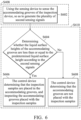
- FIG. 7 is a flowchart of an operation method of a specimen inspection machine according to another embodiment of the present invention.
- FIG. 7 is continued following step S 410 of FIG. 4 .
- the method involves using the sensing device to sense the accommodating grooves, so as to generate a plurality of third sensing signals when buffer fluids are injected into the accommodating grooves placed with the inspection samples.
- the method involves using the control device to receive the third sensing signals.
- step S 706 the method involves using the control device to determine whether the liquid surface heights of the accommodating grooves are less than or equal to the predetermined liquid surface height according to the third sensing signals.
- the method performs step S 708 .
- step S 708 the method involves the control device determining that a buffer fluid injection device is normal.
- the method performs step S 710 .
- step S 710 the method involves the control device determining that the buffer fluid injection device is abnormal and generating an abnormal signal.
- the sensing device senses the inspection device disposed on the carrying device to generate the first sensing signals, and the control device determines whether the inspection device is disposed in the correct position according to the first sensing signals.
- the sensing device senses the inspection device to generate the second sensing signals, and the control device determines whether inspection samples are placed in the accommodating grooves according to the second sensing signals to inspect the accommodating grooves placed with the inspection samples.
- the sensing device may further sense the accommodating grooves to generate the third sensing signals, and the control device determines whether the buffer fluid injection device of the specimen inspection device is normal according to the third sensing signals. Therefore, the failure of the specimen-inspection procedure may be effectively avoided, and the convenience of use is increased.
Landscapes
- Physics & Mathematics (AREA)
- Life Sciences & Earth Sciences (AREA)
- General Physics & Mathematics (AREA)
- Health & Medical Sciences (AREA)
- Chemical & Material Sciences (AREA)
- Pathology (AREA)
- Immunology (AREA)
- General Health & Medical Sciences (AREA)
- Analytical Chemistry (AREA)
- Biochemistry (AREA)
- Engineering & Computer Science (AREA)
- Spectroscopy & Molecular Physics (AREA)
- Electromagnetism (AREA)
- Urology & Nephrology (AREA)
- Medicinal Chemistry (AREA)
- Food Science & Technology (AREA)
- Molecular Biology (AREA)
- General Life Sciences & Earth Sciences (AREA)
- Geophysics (AREA)
- Hematology (AREA)
- Biomedical Technology (AREA)
- Computer Networks & Wireless Communication (AREA)
- Radar, Positioning & Navigation (AREA)
- Remote Sensing (AREA)
- Automatic Analysis And Handling Materials Therefor (AREA)
- Testing Of Devices, Machine Parts, Or Other Structures Thereof (AREA)
Abstract
Description
Claims (13)
Applications Claiming Priority (2)
| Application Number | Priority Date | Filing Date | Title |
|---|---|---|---|
| TW109100267 | 2020-01-06 | ||
| TW109100267A TWI725695B (en) | 2020-01-06 | 2020-01-06 | Specimen inspection machine and operation method thereof |
Publications (2)
| Publication Number | Publication Date |
|---|---|
| US20210208061A1 US20210208061A1 (en) | 2021-07-08 |
| US11650146B2 true US11650146B2 (en) | 2023-05-16 |
Family
ID=76604663
Family Applications (1)
| Application Number | Title | Priority Date | Filing Date |
|---|---|---|---|
| US16/853,873 Active 2041-05-26 US11650146B2 (en) | 2020-01-06 | 2020-04-21 | Specimen inspection machine and operation method thereof |
Country Status (3)
| Country | Link |
|---|---|
| US (1) | US11650146B2 (en) |
| CN (1) | CN113075393B (en) |
| TW (1) | TWI725695B (en) |
Citations (13)
| Publication number | Priority date | Publication date | Assignee | Title |
|---|---|---|---|---|
| US6184526B1 (en) * | 1997-01-08 | 2001-02-06 | Nikon Corporation | Apparatus and method for inspecting predetermined region on surface of specimen using electron beam |
| US20020117619A1 (en) * | 2001-02-26 | 2002-08-29 | Yasuhiro Gunji | Inspecting system using electron beam and inspecting method using same |
| US20040164244A1 (en) * | 1996-03-29 | 2004-08-26 | Takashi Hiroi | Electron beam inspection method and apparatus and semiconductor manufacturing method and its manufacturing line utilizing the same |
| US20080078933A1 (en) * | 1997-08-11 | 2008-04-03 | Masahiro Watanabe | Electron Beam Exposure or System Inspection Or Measurement Apparatus And Its Method And Height Detection Apparatus |
| US20100068824A1 (en) * | 2008-09-16 | 2010-03-18 | Fujifilm Corporation | Sensing method, sensing device, inspection chip, and inspection kit |
| CN201697924U (en) * | 2010-06-28 | 2011-01-05 | 台湾圆点奈米技术开发有限公司 | Magnetic bead operating platform |
| US20150031136A1 (en) * | 2013-07-24 | 2015-01-29 | Samsung Electronics Co., Ltd. | Test apparatus and method of controlling the same |
| CN104345314A (en) | 2013-08-07 | 2015-02-11 | 纬创资通股份有限公司 | Detection device and detection method for detecting whether workpiece is correctly placed |
| US20150041643A1 (en) * | 2013-08-09 | 2015-02-12 | Hitachi High-Technologies Corporation | Processing apparatus and method using a scanning electron microscope |
| US20150122993A1 (en) * | 2003-04-22 | 2015-05-07 | Ebara Corporation | Testing apparatus using charged particles and device manufacturing method using the testing apparatus |
| TWM516700U (en) * | 2015-06-23 | 2016-02-01 | Univ Chien Hsin Sci & Tech | Smart drinking machine |
| US20160178624A1 (en) * | 2014-12-22 | 2016-06-23 | Digital Biotech, LLC | Device and method to perform multiplex assays and target enrichment |
| WO2016168076A9 (en) | 2015-04-13 | 2017-06-22 | The University Of Chicago | Positron-emission tomography detector systems based on low-density liquid scintillators and precise time-resolving photodetectors |
Family Cites Families (6)
| Publication number | Priority date | Publication date | Assignee | Title |
|---|---|---|---|---|
| TWI390201B (en) * | 2008-07-18 | 2013-03-21 | Univ Fooyin | Fluid manipulation gene array analysis wafers |
| TWM445583U (en) * | 2012-08-07 | 2013-01-21 | Rbc Bioscience Corp | Device for nucleic acid extraction |
| EP2995580A1 (en) * | 2014-09-09 | 2016-03-16 | Roche Diagniostics GmbH | Laboratory sample distribution system and laboratory automation system |
| CN109791161A (en) * | 2016-07-21 | 2019-05-21 | 西门子医疗保健诊断公司 | Automated clinical analyzer system and method |
| TW201939452A (en) * | 2018-03-15 | 2019-10-01 | 艾沙技術有限公司 | Mobile vehicle, safety warning device and safety warning method |
| EP3633406B1 (en) * | 2018-07-18 | 2022-05-11 | Shenzhen Goodix Technology Co., Ltd. | Time-of-flight system and calibration method |
-
2020
- 2020-01-06 TW TW109100267A patent/TWI725695B/en active
- 2020-01-20 CN CN202010064464.4A patent/CN113075393B/en active Active
- 2020-04-21 US US16/853,873 patent/US11650146B2/en active Active
Patent Citations (14)
| Publication number | Priority date | Publication date | Assignee | Title |
|---|---|---|---|---|
| US20040164244A1 (en) * | 1996-03-29 | 2004-08-26 | Takashi Hiroi | Electron beam inspection method and apparatus and semiconductor manufacturing method and its manufacturing line utilizing the same |
| US6184526B1 (en) * | 1997-01-08 | 2001-02-06 | Nikon Corporation | Apparatus and method for inspecting predetermined region on surface of specimen using electron beam |
| US20080078933A1 (en) * | 1997-08-11 | 2008-04-03 | Masahiro Watanabe | Electron Beam Exposure or System Inspection Or Measurement Apparatus And Its Method And Height Detection Apparatus |
| US20020117619A1 (en) * | 2001-02-26 | 2002-08-29 | Yasuhiro Gunji | Inspecting system using electron beam and inspecting method using same |
| US20150122993A1 (en) * | 2003-04-22 | 2015-05-07 | Ebara Corporation | Testing apparatus using charged particles and device manufacturing method using the testing apparatus |
| US20100068824A1 (en) * | 2008-09-16 | 2010-03-18 | Fujifilm Corporation | Sensing method, sensing device, inspection chip, and inspection kit |
| CN201697924U (en) * | 2010-06-28 | 2011-01-05 | 台湾圆点奈米技术开发有限公司 | Magnetic bead operating platform |
| US20150031136A1 (en) * | 2013-07-24 | 2015-01-29 | Samsung Electronics Co., Ltd. | Test apparatus and method of controlling the same |
| US20150045930A1 (en) | 2013-08-07 | 2015-02-12 | Wistron Corporation | Test device and method for testing whether a workpiece is positioned correctly |
| CN104345314A (en) | 2013-08-07 | 2015-02-11 | 纬创资通股份有限公司 | Detection device and detection method for detecting whether workpiece is correctly placed |
| US20150041643A1 (en) * | 2013-08-09 | 2015-02-12 | Hitachi High-Technologies Corporation | Processing apparatus and method using a scanning electron microscope |
| US20160178624A1 (en) * | 2014-12-22 | 2016-06-23 | Digital Biotech, LLC | Device and method to perform multiplex assays and target enrichment |
| WO2016168076A9 (en) | 2015-04-13 | 2017-06-22 | The University Of Chicago | Positron-emission tomography detector systems based on low-density liquid scintillators and precise time-resolving photodetectors |
| TWM516700U (en) * | 2015-06-23 | 2016-02-01 | Univ Chien Hsin Sci & Tech | Smart drinking machine |
Also Published As
| Publication number | Publication date |
|---|---|
| CN113075393A (en) | 2021-07-06 |
| TWI725695B (en) | 2021-04-21 |
| US20210208061A1 (en) | 2021-07-08 |
| TW202127007A (en) | 2021-07-16 |
| CN113075393B (en) | 2022-08-23 |
Similar Documents
| Publication | Publication Date | Title |
|---|---|---|
| US9470570B2 (en) | Automatic analyzer and method for determining malfunction thereof | |
| JP4491477B2 (en) | Automatic analyzer | |
| US20090067669A1 (en) | Liquid level detecting apparatus | |
| US11796553B2 (en) | Automatic analysis system | |
| CN104034913A (en) | Sample Processing Apparatus, Sample Rack Set, And Sample Processing Method | |
| WO2017033910A1 (en) | Automatic analysis device, dispensing method, and liquid surface detection method | |
| US9255938B2 (en) | Sample analyzer and method of analyzing a sample | |
| CN110291405A (en) | Automatic analyzers and cleaning mechanisms in automatic analyzers | |
| WO2019214287A1 (en) | Detecting device and detecting method and detecting equipment therefor | |
| US11650146B2 (en) | Specimen inspection machine and operation method thereof | |
| KR102205650B1 (en) | Microfluidic device, test apparatus, test system having the same and control method for the test apparatus | |
| KR102160034B1 (en) | Test Apparatus and Control Method thereof | |
| CN111337696B (en) | In-vitro diagnosis equipment and sample analysis method thereof | |
| CN113155236B (en) | Method for judging whether liquid is entering a target container, liquid taking device and water quality analyzer | |
| KR102205900B1 (en) | Analysis apparatus and method of checking cartridge installation of the analysis apparatus | |
| KR20110099631A (en) | Liquid processing apparatus, liquid processing method and storage medium | |
| JP5993652B2 (en) | Automatic analyzer | |
| JP4898270B2 (en) | Liquid level detector and automatic analyzer | |
| CN114324924A (en) | Supporting measurement of a liquid sample | |
| JP2007315984A (en) | Automatic analyzer | |
| CN119147172A (en) | Liquid level detection method, system, device, storage medium and electronic equipment | |
| JP2007322317A (en) | Analyzer | |
| JP6407588B2 (en) | Automatic analyzer | |
| CN120769989A (en) | Automatic analysis device and abnormality determination method thereof | |
| CN117589825A (en) | automatic analysis device |
Legal Events
| Date | Code | Title | Description |
|---|---|---|---|
| AS | Assignment |
Owner name: WISTRON CORP., TAIWAN Free format text: ASSIGNMENT OF ASSIGNORS INTEREST;ASSIGNOR:WANG, CHEN-FA;REEL/FRAME:052450/0055 Effective date: 20200311 |
|
| FEPP | Fee payment procedure |
Free format text: ENTITY STATUS SET TO UNDISCOUNTED (ORIGINAL EVENT CODE: BIG.); ENTITY STATUS OF PATENT OWNER: LARGE ENTITY |
|
| STPP | Information on status: patent application and granting procedure in general |
Free format text: APPLICATION DISPATCHED FROM PREEXAM, NOT YET DOCKETED |
|
| STPP | Information on status: patent application and granting procedure in general |
Free format text: DOCKETED NEW CASE - READY FOR EXAMINATION |
|
| STPP | Information on status: patent application and granting procedure in general |
Free format text: NON FINAL ACTION MAILED |
|
| STPP | Information on status: patent application and granting procedure in general |
Free format text: RESPONSE TO NON-FINAL OFFICE ACTION ENTERED AND FORWARDED TO EXAMINER |
|
| STPP | Information on status: patent application and granting procedure in general |
Free format text: FINAL REJECTION MAILED |
|
| STCF | Information on status: patent grant |
Free format text: PATENTED CASE |