US11650103B2 - Measuring direct, diffuse, or global solar irradiance using multiple irradiance sensors - Google Patents
Measuring direct, diffuse, or global solar irradiance using multiple irradiance sensors Download PDFInfo
- Publication number
- US11650103B2 US11650103B2 US16/912,273 US202016912273A US11650103B2 US 11650103 B2 US11650103 B2 US 11650103B2 US 202016912273 A US202016912273 A US 202016912273A US 11650103 B2 US11650103 B2 US 11650103B2
- Authority
- US
- United States
- Prior art keywords
- irradiance
- sensors
- diffuse
- sensor
- ground
- Prior art date
- Legal status (The legal status is an assumption and is not a legal conclusion. Google has not performed a legal analysis and makes no representation as to the accuracy of the status listed.)
- Active, expires
Links
Images


Classifications
-
- G—PHYSICS
- G01—MEASURING; TESTING
- G01J—MEASUREMENT OF INTENSITY, VELOCITY, SPECTRAL CONTENT, POLARISATION, PHASE OR PULSE CHARACTERISTICS OF INFRARED, VISIBLE OR ULTRAVIOLET LIGHT; COLORIMETRY; RADIATION PYROMETRY
- G01J1/00—Photometry, e.g. photographic exposure meter
- G01J1/02—Details
- G01J1/0228—Control of working procedures; Failure detection; Spectral bandwidth calculation
-
- G—PHYSICS
- G01—MEASURING; TESTING
- G01J—MEASUREMENT OF INTENSITY, VELOCITY, SPECTRAL CONTENT, POLARISATION, PHASE OR PULSE CHARACTERISTICS OF INFRARED, VISIBLE OR ULTRAVIOLET LIGHT; COLORIMETRY; RADIATION PYROMETRY
- G01J5/00—Radiation pyrometry, e.g. infrared or optical thermometry
- G01J5/02—Constructional details
- G01J5/03—Arrangements for indicating or recording specially adapted for radiation pyrometers
-
- G—PHYSICS
- G01—MEASURING; TESTING
- G01J—MEASUREMENT OF INTENSITY, VELOCITY, SPECTRAL CONTENT, POLARISATION, PHASE OR PULSE CHARACTERISTICS OF INFRARED, VISIBLE OR ULTRAVIOLET LIGHT; COLORIMETRY; RADIATION PYROMETRY
- G01J1/00—Photometry, e.g. photographic exposure meter
- G01J1/02—Details
- G01J1/0219—Electrical interface; User interface
-
- G—PHYSICS
- G01—MEASURING; TESTING
- G01J—MEASUREMENT OF INTENSITY, VELOCITY, SPECTRAL CONTENT, POLARISATION, PHASE OR PULSE CHARACTERISTICS OF INFRARED, VISIBLE OR ULTRAVIOLET LIGHT; COLORIMETRY; RADIATION PYROMETRY
- G01J1/00—Photometry, e.g. photographic exposure meter
- G01J1/02—Details
- G01J1/0238—Details making use of sensor-related data, e.g. for identification of sensor or optical parts
-
- G—PHYSICS
- G01—MEASURING; TESTING
- G01J—MEASUREMENT OF INTENSITY, VELOCITY, SPECTRAL CONTENT, POLARISATION, PHASE OR PULSE CHARACTERISTICS OF INFRARED, VISIBLE OR ULTRAVIOLET LIGHT; COLORIMETRY; RADIATION PYROMETRY
- G01J1/00—Photometry, e.g. photographic exposure meter
- G01J1/02—Details
- G01J1/0242—Control or determination of height or angle information of sensors or receivers; Goniophotometry
-
- G—PHYSICS
- G01—MEASURING; TESTING
- G01J—MEASUREMENT OF INTENSITY, VELOCITY, SPECTRAL CONTENT, POLARISATION, PHASE OR PULSE CHARACTERISTICS OF INFRARED, VISIBLE OR ULTRAVIOLET LIGHT; COLORIMETRY; RADIATION PYROMETRY
- G01J1/00—Photometry, e.g. photographic exposure meter
- G01J1/42—Photometry, e.g. photographic exposure meter using electric radiation detectors
- G01J1/4228—Photometry, e.g. photographic exposure meter using electric radiation detectors arrangements with two or more detectors, e.g. for sensitivity compensation
-
- G—PHYSICS
- G01—MEASURING; TESTING
- G01J—MEASUREMENT OF INTENSITY, VELOCITY, SPECTRAL CONTENT, POLARISATION, PHASE OR PULSE CHARACTERISTICS OF INFRARED, VISIBLE OR ULTRAVIOLET LIGHT; COLORIMETRY; RADIATION PYROMETRY
- G01J1/00—Photometry, e.g. photographic exposure meter
- G01J1/42—Photometry, e.g. photographic exposure meter using electric radiation detectors
- G01J2001/4266—Photometry, e.g. photographic exposure meter using electric radiation detectors for measuring solar light
Definitions
- the disclosed subject matter is directed to the measurement of solar irradiance.
- a device or system for solar irradiance measurement comprising at least two irradiance sensors deployed outdoors at substantially different angles, such that, by analysis of readings from said irradiance sensors, direct irradiance, diffuse irradiance, and/or global irradiance are determined.
- the disclosed device or system may additionally determine ground-reflected irradiance.
- FIG. 1 depicts various components of solar radiation reaching a surface.
- FIG. 2 depicts relative responses of an irradiance sensor to radiation versus angle of incidence.
- FIG. 3 depicts an embodiment comprising two upwards-facing irradiance sensors.
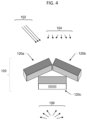
- FIG. 4 depicts an embodiment similar to FIG. 3 further comprising a downwards-facing irradiance sensor.
- FIG. 5 depicts an embodiment comprising three upwards-facing irradiance sensors.
- FIG. 6 depicts measured (data) and modeled (fit) irradiance versus time from irradiance sensors facing different directions.
- FIG. 7 A depicts a top view of an embodiment comprising four upwards-facing irradiance sensors and one downwards-facing irradiance sensor.
- FIG. 7 B depicts a side view of an embodiment comprising four upwards-facing irradiance sensors and one downwards-facing irradiance sensor.
- FIG. 7 C depicts a bottom view of an embodiment comprising four upwards-facing irradiance sensors and one downwards-facing irradiance sensor.
- FIG. 8 depicts a block diagram of an embodiment similar to FIG. 7 .
- Measurements of sunlight intensity, or solar irradiance, are important to the field of solar energy generation for purposes of both predicting and monitoring the performance of solar energy installations.
- the solar radiation striking a surface ( 18 ) may consist of multiple components, including: direct irradiance ( 102 ), comprising rays emanating directly from the sun ( 10 ); diffuse irradiance ( 104 ), comprising rays that are scattered by the atmosphere or clouds ( 12 ) prior to striking the surface ( 18 ); and ground-reflected irradiance ( 106 ), comprising rays that scatter or reflect from the ground ( 16 ) prior to striking the surface ( 18 ).
- FIG. 1 is not to scale and all rays emanating directly from the sun are nearly parallel at the earth.
- direct irradiance ( 102 ) is quantified in terms of the radiation crossing a plane normal to rays emanating from the sun ( 10 ) and this is denoted as Direct Normal Irradiance (DNI). Other measures may also be used. Direct irradiance ( 102 ) may also be denoted as beam irradiance.
- diffuse irradiance ( 104 ) is regarded as emanating equally from the entire sky dome ( 14 ). In some embodiments, diffuse irradiance ( 104 ) is regarded as having multiple components emanating from different portions of the sky dome ( 104 ). Such different components may include diffuse irradiance ( 104 ) emanating from the circumsolar disc (an angular region immediately around the sun ( 10 )), diffuse irradiance ( 104 ) emanating from the horizon, and diffuse irradiance ( 104 ) emanating from the remainder of the sky dome ( 14 ), as well as other possible components.
- diffuse irradiance ( 104 ) is quantified as the sum of all diffuse irradiance ( 104 ) components reaching the top of a horizontal plane surface and this sum is denoted as Diffuse Horizontal Irradiance (DHI); in some embodiments various components of this sum are treated separately. Other measures of may also be used.
- DHI Diffuse Horizontal Irradiance
- ground-reflected irradiance ( 106 ) may be quantified as the total reflected irradiance, generally diffuse, emanating upwards from the ground ( 16 ) and measured in a downward-facing horizontal plane, and may be denoted Ground-Reflected Irradiance (GRI).
- ground-reflected irradiance ( 106 ) is quantified in terms of albedo ⁇ , the ground-surface reflectivity or the ratio of upwelling irradiance (GRI) to downwelling irradiance (GHI). Other measures may also be used.
- GTI Global Tilted Irradiance
- the relative response ( 44 ) of an irradiance sensor ( 120 ) to radiation ( 40 ) decreases as the angle of incidence ⁇ inc increases.
- the graph depicts relative response ( 44 ) versus angle of incidence ⁇ inc ( 42 ).
- the relative response decreases only as the cosine of ⁇ inc as shown by ( 46 ), i.e. in direct proportion to the reduction of its apparent cross-sectional area with respect to radiation ( 40 ).
- Irradiance sensors ( 120 ) may include, but are not limited, to pyranometers and photovoltaic (PV) reference cells.
- PV reference cells Pyranometers by design have a relative incidence-angle response close to the ideal ( 46 ), achieved by using a domed glass entrance window or a diffuser.
- PV reference cells by contrast, have a flat glass entrance window similar to a small solar panel; accordingly reflection losses increase as a function of ⁇ inc and their incidence-angle response ( 48 ) is lower than that of pyranometers at high ⁇ inc .
- the difference may be significant; for measurement of GHI in clear-sky conditions, a PV reference cell may measure ⁇ 6% less integrated irradiance over a full day relative to a pyranometer, due to its lower response at high ⁇ inc .
- irradiance sensors ( 120 ) are depicted in a form representative of PV reference cells. However, other types of irradiance sensors ( 120 ), including pyranometers, could be substituted.
- a device or system for solar irradiance measurement comprising at least two upwards-facing irradiance sensors ( 120 ) deployed outdoors at substantially different angles, such that, by analysis of readings from irradiance sensors ( 120 ), direct ( 102 ), diffuse ( 104 ), and/or global irradiance are determined.
- a device or system further comprising at least one downwards-facing irradiance sensor ( 120 ), such that, by analysis of readings from irradiance sensors ( 120 ), direct ( 102 ), diffuse ( 104 ), and/or global irradiance are determined together with ground-reflected irradiance.
- FIG. 3 depicts one embodiment of the disclosed subject matter.
- Two sky-facing irradiance sensors ( 120 ) are mounted at substantially different angular orientations.
- one irradiance sensor ( 120 a ) faces south at an approximately 25-degree tilt angle
- a second irradiance sensor ( 120 b ) faces north at an approximately 25-degree tilt angle.
- Direct ( 102 ), diffuse ( 104 ), and ground-reflected irradiance ( 106 ) are present.
- G direct , G diffuse , and G ground-reflected are direct ( 102 ), diffuse ( 104 ), and ground-reflected ( 106 ) irradiance (or DNI, DHI, GRI), and a 1 , b 1 , and c 1 are coefficients quantifying the contribution of these irradiance components to the total detected irradiance.
- Coefficient a 1 is determined at least by the cosine of the angle of incidence ⁇ inc between the rays of direct irradiance ( 102 ) and the normal to the plane of first irradiance sensor ( 120 a ), as well as by the additional non-cosine portion of the incidence-angle response of first irradiance sensor ( 120 a ), e.g. as in ( 48 ) in the example in FIG. 2 .
- Coefficient b 1 is determined at least by the angle between first irradiance sensor ( 120 a ) and the vertical (center of the sky dome ( 14 )), as well as by said incidence-angle response of first irradiance sensor ( 120 a ).
- Coefficient c 1 is also determined at least by the angle between first irradiance sensor ( 120 a ) and the horizontal, as well as by said incidence-angle response of first irradiance sensor ( 120 a ). Since coefficients a 1 , b 1 , and c 1 are determined by properties of irradiance sensor ( 120 a ), its orientation, and the position of the sun ( 10 ), their values at a point in time may be calculated using appropriate models for given latitude and longitude.
- An exemplary model for determining diffuse irradiance ( 104 ) on a tilted plane as a function of DNI and DHI is provided by Perez, et al, Solar Energy 44 (5), 271-289, 1990 (incorporated herein by reference).
- the third terms of Eq. (1) and Eq. (2) are neglected.
- coefficients c 1 and c 2 become negligible, especially for irradiance sensors ( 120 ) having less-than-cosine incidence angle response as ( 48 ) in FIG. 2 .
- G 1 and G 2 Eqs. (1) and (2) may be directly solved to determine G direct and G diffuse or equivalently DNI and DHI. Equivalently, from these values GHI and/or GTI may be calculated.
- ground-reflected irradiance ( 106 ), G ground-reflected is not neglected but is assumed to have a known small value (for example, calculated from G direct and G diffuse and the known reflectivity or albedo ⁇ of the surrounding ground surface). In this case, Eqs. (1) and (2) may again be solved to determine G direct and G diffuse .
- FIG. 4 depicts an embodiment similar to FIG. 3 but additionally comprising a third downwards-facing irradiance sensor ( 120 c ) oriented towards ground-reflected irradiance ( 106 ).
- downwards-facing irradiance sensor ( 120 c ) is oriented directly downward and has broad angular response, such that c 3 is assumed equal to one for practical purposes, while in other embodiments c 3 may have other values.
- Eqs. (1), (2), and (3) may be solved to determine G direct , G diffuse , and G ground-reflected or equivalently DNI, DHI, and GRI. Equivalently, from these values GHI and/or GTI may be calculated.
- FIG. 5 depicts another embodiment, comprising three upwards-facing irradiance sensors ( 120 d , 120 e , 120 f ), each with approximately 25-degree tilt and with azimuthal orientations distributed approximately equally around 360 degrees of arc.
- one irradiance sensor ( 120 d ) in FIG. 5 is intended to be directed approximately north or south.
- the use of three upwards-facing irradiance sensors ( 120 ) provides better ability to determine irradiance components G direct and G diffuse .
- inclusion of a third upwards-facing irradiance sensor ( 120 ) as in FIG. 5 overcomes this limitation.
- inclusion of third upwards-facing irradiance sensor ( 120 ) as in FIG. 5 may result in measurement equations that are typically over-determined, i.e. contain more knowns than unknowns, resulting in lower uncertainty.
- two or more irradiance sensors ( 120 ) are oriented at different angles than those depicted in FIG. 3 , FIG. 4 , or FIG. 5 , and irradiance components G direct , G diffuse , and/or G ground-reflected are similarly determined by analysis of the readings of the two or more irradiance sensors ( 120 ).
- an embodiment could contain any number of upwards-facing irradiance sensors ( 120 ) oriented along different directions, in order to better determine the irradiance components.
- an embodiment could contain an arbitrary number of irradiance sensors ( 120 ) oriented in different directions, including upwards- and downwards-facing irradiance sensors ( 120 ) or additionally vertically oriented irradiance sensors ( 120 ).
- the measurement may be exactly determined (same number of measurements and unknowns) or over-determined (more measurements than unknowns).
- the orientations of the irradiance sensors ( 120 ) are substantially different so that the multiple readings provide enough information for successful calculation despite measurement and modeling error.
- the mathematical representation may be generalized.
- G (i),pred ⁇ ( ⁇ z , ⁇ s ,DNI,DHI, ⁇ (i) , ⁇ (i) ,S (i) ) (4)
- ⁇ z and ⁇ s are the solar zenith and azimuth angles
- DNI and DHI are the direct normal and diffuse horizontal irradiance at the time point
- ⁇ (i) and ⁇ (i) are the tilt and azimuth angles of irradiance sensor i
- S (i) is a vector of constants for sensor i which may quantify incidence-angle response and other sensor-specific parameters.
- the function ⁇ includes a sum of terms for the contributions of direct ( 102 ), diffuse ( 104 ), and ground-reflected ( 106 ) irradiance.
- ⁇ could be expanded as the sum of three terms such that
- G ( i ) , pred IAM ( i ) , dir ⁇ DNI ⁇ cos ⁇ ( ⁇ ( i ) , inc ) + IAM ( i ) , diff ⁇ DHI ⁇ ( 1 + cos ⁇ ⁇ ⁇ ( i ) 2 ) + IAM ( i ) , g ⁇ ⁇ r ⁇ ⁇ ⁇ ( DNI ⁇ cos ⁇ ⁇ ⁇ z + DHI ) ⁇ ( 1 - cos ⁇ ⁇ ⁇ ( i ) 2 ) ( 5 )
- ⁇ (i),inc is the solar angle of incidence on sensor i, which is a function of ⁇ z , ⁇ s , ⁇ (i) , and ⁇ (i) , ⁇ is the ground surface albedo
- IAM (i),dir , IAM (i),diff , and IAM (i),gr are incidence angle modifiers for direct, diffuse, and ground-reflected radiation
- IAM (i),dir is a function of ⁇ (i),inc that quantifies the ratio of sensor i response to a cosine function (e.g. the ratio of ( 48 ) to ( 46 ));
- IAM (i),diff and IAM (i),gr are scalars that quantify the relative fraction of diffuse irradiance ( 104 ) and ground-reflected irradiance ( 106 ), respectively, for which sensor i is responsive (e.g. calculated from integrals over ( 48 )). These terms may include constants based on the sensor properties parameterized by S (i) .
- Equation (5) is a simplified model.
- the terms for diffuse irradiance ( 104 ) are further separated at least into circumsolar, sky, and horizon components.
- the diffuse irradiance ( 104 ) reaching an arbitrary surface ( 18 ) may become a function of both DNI and DHI.
- Irradiance measured in one plane can be effectively transposed to another plane, such as the plane of sensor i, by a model such as the “Perez” model described in R. Perez, P. Ineichen, R. Seals, J. Michalsky, and R.
- equations for irradiance detected by each irradiance sensor ( 120 ) are solved algebraically to directly yield values for direct ( 102 ), diffuse ( 104 ), and/or ground-reflected ( 106 ) irradiance.
- trial values for direct ( 102 ), diffuse ( 104 ), and/or ground-reflected ( 106 ) irradiance are iteratively adjusted to yield best fit between predicted and measured readings of the irradiance sensors ( 120 ) (e.g. Eqs.
- measurements from individual irradiance sensors may be each broken into direct ( 102 ), diffuse ( 104 ), and/or ground-reflected ( 106 ) irradiance components using an irradiance decomposition model which estimates components contributing to a global irradiance, such as the DIRINT or GTI-DIRINT model (Bill Marion, “A model for deriving the direct normal and diffuse horizontal irradiance from the global tilted irradiance”, Solar Energy , v. 122, pp.
- an irradiance decomposition model which estimates components contributing to a global irradiance, such as the DIRINT or GTI-DIRINT model (Bill Marion, “A model for deriving the direct normal and diffuse horizontal irradiance from the global tilted irradiance”, Solar Energy , v. 122, pp.
- final values for direct ( 102 ), diffuse ( 104 ), and/or ground-reflected ( 106 ) irradiance may be determined from the collection of individually-derived values, such as by averaging the individually derived values among the multiple irradiance sensors ( 120 ) or iterative operation of the models until convergence is achieved.
- calculation to separate direct ( 102 ) and diffuse ( 104 ) irradiance components may be accomplished by using at least two upwards-facing irradiance sensors ( 120 ) having substantially different orientation.
- substantially different may be quantified by a minimum threshold on the difference of the cosine of the solar angle of incidence upon at least one pair of irradiance sensors ( 120 ).
- a minimum difference of at least 0.05 or at least 0.1 in the cosine may be considered substantially different to allow successful calculation, while smaller differences in cosine of solar angle of incidence produce degenerate measurement equations that cannot be reliably solved. Other measures of degeneracy could also be used.
- orientations of irradiance sensors ( 120 ) are chosen to minimize the number of hours of degeneracy for a given location throughout the year. Exemplary such embodiments suitable for a wide range of latitudes are depicted in FIG. 5 and FIG. 7 .
- the device or system may estimate direct ( 102 ) and/or diffuse ( 104 ) irradiance using an a decomposition model, such as the DIRINT or GTI-DIRINT decomposition models referenced above or through other estimation models including models relying on a time series of data.
- a device or system automatically switches between calculation of direct ( 102 ), diffuse ( 104 ), and/or ground-reflected ( 106 ) irradiance components from solution of measurement equations to estimation of these components using decomposition or other models; in some embodiments, said automatic switching is performed based on estimates of the degeneracy of the measurement equations at a particular time point, e.g.
- calculation of results may be accomplished with knowledge of the angular orientations of each irradiance sensor i (tilt ⁇ (i) and azimuth ⁇ (i) with respect to earth coordinates).
- irradiance sensors are fixed by construction in a particular arrangement wherein their relative tilt angles and azimuthal orientations are known, such that determination of an overall device or system tilt ⁇ 0 and azimuthal orientation ⁇ 0 may be made for a particular installation and all individual tilt ⁇ (i) and azimuth ⁇ (i) may be computed by known relative differences from the device or system ⁇ 0 and ⁇ 0 .
- tilt ⁇ 0 may be determined by requiring leveling of a device or system upon installation. In some embodiments tilt ⁇ 0 may be automatically measured by an included tilt sensor or inclinometer.
- an electronic compass is included to facilitate automatic determination of azimuthal orientation ⁇ 0 .
- said compass readings are automatically corrected for magnetic declination at the installation site latitude and longitude using a lookup table, function, or similar means.
- azimuthal orientation ⁇ 0 is automatically determined from measurements by irradiance sensors ( 120 ). This may be performed, for example, by treating azimuthal orientations ( ⁇ (i) and/or ⁇ 0 wherein ⁇ (i) are fixed relative to ⁇ 0 ) as one or more additional unknowns in the measurement equations (Eqs. (1)-(6) and analogues for other models or arrangements of sensors) which are determined by direct solution of the multiple equations or iterative fitting of measured data to determine optimized values, including using time series of data. For example, during clear-sky conditions, the time series data of a tilted irradiance sensor will depend on its azimuthal orientation, such that by analyzing the time series data azimuthal orientation may be determined.
- clear-sky conditions are automatically detected from irradiance readings, allowing automatic determination of azimuthal orientation.
- clear-sky conditions are detected based on irradiance level relative to modeled clear-sky expectations for the location.
- clear-sky conditions are detected based on statistical fluctuation of time series data, wherein lower fluctuation is more correlated with clear skies. Automatic determination of azimuthal orientation may be performed once upon installation and/or at routine intervals.
- FIG. 6 illustrates automatic determination of azimuthal orientations by fitting time series data.
- the figure depicts measurements of irradiance sensors ( 120 ) in an embodiment similar to FIG. 5 , with irradiance ( 224 ) versus time ( 222 ) on two consecutive days.
- Three irradiance sensors ( 120 d , 120 e , 120 f ) facing nominally north, southeast, and southwest have measured data shown as ( 202 ), ( 204 ), ( 206 ) respectively and model fits as ( 212 ), ( 214 ), ( 216 ).
- the irradiance ( 224 ) profile measured on each irradiance sensor ( 120 d , 120 e , 120 f ) depends critically on time ( 222 ) according to its azimuthal orientation.
- the morning of the first day in FIG. 6 is identified as cloudy due to fluctuations in irradiance, while the first afternoon and the entire second day are identified as having clear-sky conditions due to the expected profile and low fluctuations. Fitting of the data using azimuthal orientations as one or more free variables allows precise determination of ⁇ 0 and/or ⁇ (i) .
- calculation of results may be accomplished with accurate knowledge of latitude and longitude of the device or system together with accurate time.
- a user provides input for latitude and longitude of the installation site.
- a Global Positioning System GPS is also included within the device or system to facilitate automatic determination of latitude and longitude.
- latitude and longitude may be additional unknowns to be determined by fitting.
- a system or device comprises a computing element ( 270 ) which records measurements of irradiance sensors ( 120 ), analyzes results, and performs other tasks.
- computing element ( 270 ) is contained within or collocated with irradiance sensors ( 120 ). In one embodiment, computing element ( 270 ) is remote.
- irradiance sensors ( 120 ) are combined into a single enclosure as a unit.
- FIGS. 7 A, 7 B, and 7 C together depict an exemplary embodiment in which five irradiance sensors ( 120 )—four sky-facing irradiance sensors ( 120 g , 120 h , 120 k , 120 m ) and one ground-facing irradiance sensor ( 120 n )—are integrated into a single device.
- FIG. 7 A is a top view
- FIG. 7 B is a side view
- FIG. 7 C is a bottom view.
- the device comprises an enclosure ( 250 ) whose top side has a pyramidal shape.
- the four sky-facing irradiance sensors ( 120 g , 120 h , 120 k , 120 m ) are at 25-degree tilt and face different compass directions.
- a recess ( 256 ) on the bottom side of the device provides a mounting location ( 254 ) for a mounting bracket, and an electrical connector ( 252 ) provides for power and communication signals.
- a computing element ( 270 ) is included to automatically process readings from the irradiance sensors ( 120 ) and calculate results.
- a tilt sensor ( 280 ), electronic compass ( 282 ), accurate clock ( 284 ), and/or GPS receiver ( 286 ) are included.
- FIG. 8 depicts a block diagram of an exemplary embodiment similar to FIG. 7 , comprising four sky-facing irradiance sensors ( 120 g , 120 h , 120 k , 120 m ); one ground-facing irradiance sensor ( 120 n ); a computing element ( 270 ) which processes readings from irradiance sensors ( 120 ), calculates results, and performs other tasks; a tilt sensor ( 280 ) to determine system ⁇ 0 ; electronic compass ( 282 ) to assist in determining ⁇ 0 ; accurate clock ( 284 ); GPS receiver ( 286 ) for determining latitude, longitude, and/or time; and/or communication circuitry ( 272 ).
- irradiance sensors ( 120 ) are routinely cleaned by personnel or automated equipment to remove the accumulation of soiling particles which reduce the measured irradiance.
- a soiling measurement device is coupled with the device or system in order to measure the extent of soiling particle accumulation on one or more of irradiance sensors ( 120 ) such that readings of one or more irradiance sensors ( 120 ) are corrected for losses due to soiling.
- the soiling measurement device could comprise, for example, a MarsTM soiling sensor (Gostein et al, “Mars Soiling SensorTM” 2018 IEEE 7th World Conference on Photovoltaic Energy Conversion Joint Conference of 45th IEEE PVSC, 2018, pp. 3417-3420, incorporated herein by reference), or another similar or related device.
- soiling, fouling, degradation, or malfunction of one or more of irradiance sensors ( 120 ) may be automatically determined.
- determination of soiling, fouling, degradation, or malfunction is performed by intercomparing readings of sky-facing irradiance sensors ( 120 ) during cloudy conditions when their irradiance readings may be identical despite their different orientations. Sufficiently cloudy conditions may be automatically detected from irradiance and irradiance fluctuation levels.
- determination of soiling, fouling, degradation, or malfunction is performed during clear-sky conditions, during which sky-facing irradiance sensors ( 120 ) read differently due to different orientation.
- this is accomplished by comparing the reading of each irradiance sensor ( 120 ) to a predicted clear-sky value using a model. In some embodiments this is accomplished by using a decomposition model to estimate direct ( 102 ) and/or diffuse ( 104 ) irradiance from the reading of each irradiance sensor ( 120 ) and comparing the decomposed values. In some embodiments, souling, fouling, degradation, or malfunction of a ground-facing irradiance sensor ( 120 ) is performed by comparing measured albedo to expectations. In some embodiments any of the mentioned comparisons may be performed automatically at routine intervals.
- a ratio of actual to predicted or modeled irradiance readings is used to quantify the soiling, fouling, degradation or malfunction of each irradiance sensor ( 120 ).
- the readings of one or more individual irradiance sensors ( 120 ) may be automatically corrected or alerts may be provided indicating a sensor is out-of-tolerance.
- a disclosed device or system is used to measure a global irradiance using a type of irradiance sensor ( 120 ), such as a PV reference cell with a flat glass window, that would normally be inaccurate for measuring a global irradiance due to excessive non-cosine dependence of response versus incidence angle.
- a type of irradiance sensor 120
- a PV reference cell has significantly reduced response at high incidence angle relative to the ideal cosine response.
- GHI or GTI this may result in on the order of 6% integrated error over the course of a clear day or on the order of 5% instantaneous error during cloudy conditions.
- correction for this effect can be performed but only if the relative intensities of direct ( 102 ) and diffuse ( 104 ) irradiance are known. Therefore, in some embodiments, multiple sky-facing irradiance sensors ( 120 ) are used to determine direct ( 102 ) and diffuse ( 104 ) irradiance from which an accurate global irradiance, corrected for irradiance sensor ( 120 ) angular response, is determined. In such embodiments where the objective is only measurement of a global irradiance, accuracy requirements for calculation of the underlying direct ( 102 ) and diffuse ( 104 ) irradiance components are lessened, and these components may or may not be reported to a user. Correction of downward-facing irradiance sensor ( 120 ) for incidence angle response may also be performed by using pre-calculated incidence angle modifiers for ground-reflected diffuse and direct irradiance components.
- a device or system computes and/or measures any of a number of irradiance components or metrics which may be derived from the readings of irradiance sensors ( 120 ), including: direct irradiance ( 102 ), diffuse irradiance ( 104 ), ground-reflected irradiance ( 106 ), global horizontal irradiance, plane-of-array irradiance, global tilted irradiance on an arbitrary plane, albedo (ratio of horizontal upwelling to horizontal downwelling irradiance), and others.
Landscapes
- Physics & Mathematics (AREA)
- Spectroscopy & Molecular Physics (AREA)
- General Physics & Mathematics (AREA)
- Engineering & Computer Science (AREA)
- Human Computer Interaction (AREA)
- Photometry And Measurement Of Optical Pulse Characteristics (AREA)
- Investigating Or Analysing Materials By Optical Means (AREA)
Abstract
Description
G 1 =a 1 ·G direct +b 1 ·G diffuse +c 1 ·G ground-reflected (1)
where Gdirect, Gdiffuse, and Gground-reflected are direct (102), diffuse (104), and ground-reflected (106) irradiance (or DNI, DHI, GRI), and a1, b1, and c1 are coefficients quantifying the contribution of these irradiance components to the total detected irradiance. Coefficient a1 is determined at least by the cosine of the angle of incidence θinc between the rays of direct irradiance (102) and the normal to the plane of first irradiance sensor (120 a), as well as by the additional non-cosine portion of the incidence-angle response of first irradiance sensor (120 a), e.g. as in (48) in the example in
G 2 =a 2 ·G direct +b 2 ·G diffuse +c 2 ·G ground-reflected (2)
Coefficients a2, b2, and c2 are determined analogously to a1, b1, and c1, but their values are different because second irradiance sensor (120 b) is oriented in a different direction.
G 3 =c 3 ·G ground-reflected (3)
where c3 is again a function of the orientation and angular response of third downwards-facing irradiance sensor (120 c). In some embodiments downwards-facing irradiance sensor (120 c) is oriented directly downward and has broad angular response, such that c3 is assumed equal to one for practical purposes, while in other embodiments c3 may have other values. In some embodiments of the arrangement depicted in
G (i),pred=ƒ(θz,γs ,DNI,DHI,β (i),γ(i) ,S (i)) (4)
where θz and γs are the solar zenith and azimuth angles, DNI and DHI are the direct normal and diffuse horizontal irradiance at the time point, β(i) and γ(i) are the tilt and azimuth angles of irradiance sensor i, and S(i) is a vector of constants for sensor i which may quantify incidence-angle response and other sensor-specific parameters.
where θ(i),inc is the solar angle of incidence on sensor i, which is a function of θz, γs, β(i), and γ(i), ρ is the ground surface albedo, and IAM(i),dir, IAM(i),diff, and IAM(i),gr are incidence angle modifiers for direct, diffuse, and ground-reflected radiation, respectively, on sensor i. IAM(i),dir is a function of θ(i),inc that quantifies the ratio of sensor i response to a cosine function (e.g. the ratio of (48) to (46)); IAM(i),diff and IAM(i),gr are scalars that quantify the relative fraction of diffuse irradiance (104) and ground-reflected irradiance (106), respectively, for which sensor i is responsive (e.g. calculated from integrals over (48)). These terms may include constants based on the sensor properties parameterized by S(i).
GOF=Σi(G (i),pred −G (i),meas)2 (6)
which, in some embodiments, may be performed by iterative adjustment of trial values.
Claims (6)
Priority Applications (3)
| Application Number | Priority Date | Filing Date | Title |
|---|---|---|---|
| US16/912,273 US11650103B2 (en) | 2019-06-25 | 2020-06-25 | Measuring direct, diffuse, or global solar irradiance using multiple irradiance sensors |
| US17/214,978 US20210231490A1 (en) | 2019-06-25 | 2021-03-29 | Measuring Direct, Diffuse, Global, and/or Ground-Reflected Solar Irradiance Using an Array of Irradiance Sensors |
| US17/547,293 US20220099483A1 (en) | 2019-06-25 | 2021-12-10 | Measuring Direct, Diffuse, Global, and/or Ground-Reflected Solar Irradiance Using an Array of Irradiance Sensors |
Applications Claiming Priority (3)
| Application Number | Priority Date | Filing Date | Title |
|---|---|---|---|
| US201962866592P | 2019-06-25 | 2019-06-25 | |
| US201962938003P | 2019-11-20 | 2019-11-20 | |
| US16/912,273 US11650103B2 (en) | 2019-06-25 | 2020-06-25 | Measuring direct, diffuse, or global solar irradiance using multiple irradiance sensors |
Related Child Applications (1)
| Application Number | Title | Priority Date | Filing Date |
|---|---|---|---|
| US17/214,978 Continuation-In-Part US20210231490A1 (en) | 2019-06-25 | 2021-03-29 | Measuring Direct, Diffuse, Global, and/or Ground-Reflected Solar Irradiance Using an Array of Irradiance Sensors |
Publications (2)
| Publication Number | Publication Date |
|---|---|
| US20200408605A1 US20200408605A1 (en) | 2020-12-31 |
| US11650103B2 true US11650103B2 (en) | 2023-05-16 |
Family
ID=74044542
Family Applications (1)
| Application Number | Title | Priority Date | Filing Date |
|---|---|---|---|
| US16/912,273 Active 2040-08-10 US11650103B2 (en) | 2019-06-25 | 2020-06-25 | Measuring direct, diffuse, or global solar irradiance using multiple irradiance sensors |
Country Status (1)
| Country | Link |
|---|---|
| US (1) | US11650103B2 (en) |
Cited By (1)
| Publication number | Priority date | Publication date | Assignee | Title |
|---|---|---|---|---|
| US20220099483A1 (en) * | 2019-06-25 | 2022-03-31 | Michael Gostein | Measuring Direct, Diffuse, Global, and/or Ground-Reflected Solar Irradiance Using an Array of Irradiance Sensors |
Families Citing this family (2)
| Publication number | Priority date | Publication date | Assignee | Title |
|---|---|---|---|---|
| CN117856734A (en) * | 2023-12-20 | 2024-04-09 | 仁卓智能科技有限公司 | Self-identification method, self-identification device, double-sided photovoltaic system, and computer-readable storage medium |
| WO2025205925A1 (en) * | 2024-03-28 | 2025-10-02 | 国立研究開発法人農業・食品産業技術総合研究機構 | Solar radiation amount calculation method and solar radiation amount calculating device |
Citations (12)
| Publication number | Priority date | Publication date | Assignee | Title |
|---|---|---|---|---|
| US4491727A (en) | 1981-07-01 | 1985-01-01 | Ramot University Authority For Applied Research | Solar radiation sensor and system including same for measuring solar radiation distribution |
| US5148012A (en) * | 1991-10-15 | 1992-09-15 | C & A Technology | Solar tracking device having three sensors separated by four semicircular vanes |
| US20130048048A1 (en) | 2011-08-22 | 2013-02-28 | Kent Flanery | System and methods for controlling solar module trackers |
| US8455806B2 (en) * | 2010-01-18 | 2013-06-04 | Sunpower Corporation | Photovoltaic assembly for use in diffuse weather conditions and related methods |
| US8972221B2 (en) | 2007-02-12 | 2015-03-03 | Locus Energy, Llc | Estimating solar irradiance components from plane of array irradiance and global horizontal irradiance |
| US20160237745A1 (en) | 2013-10-03 | 2016-08-18 | Philips Lighting Holding B.V. | A window shading control system and method thereof based on decomposed direct and diffuse solar radiations |
| US20170097259A1 (en) | 2015-10-06 | 2017-04-06 | View, Inc. | Multi-sensor |
| US20170276542A1 (en) | 2014-09-29 | 2017-09-28 | View, Inc. | Combi-sensor systems |
| US20180331653A1 (en) | 2017-05-12 | 2018-11-15 | Michael Gostein | Optical Soiling Measurement Device for Photovoltaic Arrays |
| US20180341002A1 (en) | 2017-05-24 | 2018-11-29 | Augustyn + Company | Method, system, and apparatus for rapidly measuring incident solar irradiance on multiple planes of differing angular orientations |
| US20180343367A1 (en) | 2017-01-17 | 2018-11-29 | Micasense, Inc. | Multi-sensor irradiance estimation |
| US10533892B2 (en) | 2015-10-06 | 2020-01-14 | View, Inc. | Multi-sensor device and system with a light diffusing element around a periphery of a ring of photosensors and an infrared sensor |
-
2020
- 2020-06-25 US US16/912,273 patent/US11650103B2/en active Active
Patent Citations (12)
| Publication number | Priority date | Publication date | Assignee | Title |
|---|---|---|---|---|
| US4491727A (en) | 1981-07-01 | 1985-01-01 | Ramot University Authority For Applied Research | Solar radiation sensor and system including same for measuring solar radiation distribution |
| US5148012A (en) * | 1991-10-15 | 1992-09-15 | C & A Technology | Solar tracking device having three sensors separated by four semicircular vanes |
| US8972221B2 (en) | 2007-02-12 | 2015-03-03 | Locus Energy, Llc | Estimating solar irradiance components from plane of array irradiance and global horizontal irradiance |
| US8455806B2 (en) * | 2010-01-18 | 2013-06-04 | Sunpower Corporation | Photovoltaic assembly for use in diffuse weather conditions and related methods |
| US20130048048A1 (en) | 2011-08-22 | 2013-02-28 | Kent Flanery | System and methods for controlling solar module trackers |
| US20160237745A1 (en) | 2013-10-03 | 2016-08-18 | Philips Lighting Holding B.V. | A window shading control system and method thereof based on decomposed direct and diffuse solar radiations |
| US20170276542A1 (en) | 2014-09-29 | 2017-09-28 | View, Inc. | Combi-sensor systems |
| US20170097259A1 (en) | 2015-10-06 | 2017-04-06 | View, Inc. | Multi-sensor |
| US10533892B2 (en) | 2015-10-06 | 2020-01-14 | View, Inc. | Multi-sensor device and system with a light diffusing element around a periphery of a ring of photosensors and an infrared sensor |
| US20180343367A1 (en) | 2017-01-17 | 2018-11-29 | Micasense, Inc. | Multi-sensor irradiance estimation |
| US20180331653A1 (en) | 2017-05-12 | 2018-11-15 | Michael Gostein | Optical Soiling Measurement Device for Photovoltaic Arrays |
| US20180341002A1 (en) | 2017-05-24 | 2018-11-29 | Augustyn + Company | Method, system, and apparatus for rapidly measuring incident solar irradiance on multiple planes of differing angular orientations |
Non-Patent Citations (6)
| Title |
|---|
| B. Marion, "Multi-Pyranometer Array Design and Performance Summary," Proceedings of the 1998 American Solar Energy Society Annual Conference, Albuquerque, NM, Jun. 14-17, 1998. |
| B. Steinmuller, "The Two Solarimeter Method for Insolation on Inclined Surfaces," Solar Energy, v. 25, pp. 449-460, 1980. |
| B.K. Munger, et al., "An Improved Multipyranometer Array for the Measurement of Direct and Diffuse Solar Radiation," Proceedings of the Ninth Symposium on Improving Building Systems in Hot and Humid Climates, Arlington, TX, May 19-20, 1994. |
| D. Faiman, et al., "Site-Independent Algorithm for Obtaining the Direct Beam Insolation from a Multi-Pyranometer Instrument," Solar Energy, v. 50, pp. 53-57, 1993. |
| J.-C. Baltazar et al., "Improved Methodology to Evaluate Clear-Sky Direct Normal Irradiance with a Multi-Pyranometer Array," Solar Energy, v. 121, pp. 123-130, 2015. |
| J.-C. Baltazar et al., "Improved Methodology to Measure Normal Incident Solar Radiation with a Multi-Pyranometer Array," Energy Procedia, v. 57, pp. 1211-1219, 2014. |
Cited By (1)
| Publication number | Priority date | Publication date | Assignee | Title |
|---|---|---|---|---|
| US20220099483A1 (en) * | 2019-06-25 | 2022-03-31 | Michael Gostein | Measuring Direct, Diffuse, Global, and/or Ground-Reflected Solar Irradiance Using an Array of Irradiance Sensors |
Also Published As
| Publication number | Publication date |
|---|---|
| US20200408605A1 (en) | 2020-12-31 |
Similar Documents
| Publication | Publication Date | Title |
|---|---|---|
| Elminir et al. | Optimum solar flat-plate collector slope: case study for Helwan, Egypt | |
| Marion et al. | A practical irradiance model for bifacial PV modules | |
| US11650103B2 (en) | Measuring direct, diffuse, or global solar irradiance using multiple irradiance sensors | |
| Muzathik et al. | Estimation of global solar irradiation on horizontal and inclined surfaces based on the horizontal measurements | |
| Hartley et al. | The optimisation of the angle of inclination of a solar collector to maximise the incident solar radiation | |
| Raptis et al. | Measurements and model simulations of solar radiation at tilted planes, towards the maximization of energy capture | |
| Kamali et al. | Estimating solar radiation on tilted surfaces with various orientations: a study case in Karaj (Iran) | |
| US20130314699A1 (en) | Solar resource measurement system | |
| Marion | A model for deriving the direct normal and diffuse horizontal irradiance from the global tilted irradiance | |
| Riley et al. | A performance model for bifacial PV modules | |
| Li et al. | Relationship between the total solar radiation on tilted surfaces and the sunshine hours in Hong Kong | |
| US20220099483A1 (en) | Measuring Direct, Diffuse, Global, and/or Ground-Reflected Solar Irradiance Using an Array of Irradiance Sensors | |
| US20210231490A1 (en) | Measuring Direct, Diffuse, Global, and/or Ground-Reflected Solar Irradiance Using an Array of Irradiance Sensors | |
| Chiodetti | Bifacial PV plants: performance model development and optimization of their configuration | |
| Nievinski | Forward and inverse modeling of GPS multipath for snow monitoring | |
| Mraoui et al. | Optimum tilt angle of a photovoltaic system: Case study of Algiers and Ghardaia | |
| EP3839452B1 (en) | System for simultaneously calibrating two or more solar radiation measuring pyranometers | |
| Menyhart et al. | A new method for checking the leveling of pyranometers | |
| Gueymard et al. | Progress in sky radiance and luminance modeling using circumsolar radiation and sky view factors | |
| Alam et al. | Resolution in photovoltaic potential computation | |
| Cebecauer et al. | High-resolution digital elevation model for improved PV yield estimates | |
| Bangarigadu et al. | Analysis of solar power and energy variability through site adaptation of satellite data with quality controlled measured solar radiation data | |
| Peter et al. | The Optimal Tilt Angle for Maximizing Energy Production from Bifacial solar Panels Under Varying Height in Tropical Regions | |
| Wang et al. | High-resolution 3D solar potential assessment reveals significant shading-driven overestimation in dense urban areas | |
| US20240402005A1 (en) | Solar Irradiance Sensor with Diffuse Isolator |
Legal Events
| Date | Code | Title | Description |
|---|---|---|---|
| FEPP | Fee payment procedure |
Free format text: ENTITY STATUS SET TO UNDISCOUNTED (ORIGINAL EVENT CODE: BIG.); ENTITY STATUS OF PATENT OWNER: SMALL ENTITY |
|
| AS | Assignment |
Owner name: ATONOMETRICS, INC., TEXAS Free format text: ASSIGNMENT OF ASSIGNORS INTEREST;ASSIGNORS:GOSTEIN, MICHAEL;STUEVE, WILLIAM;SIGNING DATES FROM 20200625 TO 20200626;REEL/FRAME:053050/0372 |
|
| FEPP | Fee payment procedure |
Free format text: ENTITY STATUS SET TO SMALL (ORIGINAL EVENT CODE: SMAL); ENTITY STATUS OF PATENT OWNER: SMALL ENTITY |
|
| STPP | Information on status: patent application and granting procedure in general |
Free format text: DOCKETED NEW CASE - READY FOR EXAMINATION |
|
| STPP | Information on status: patent application and granting procedure in general |
Free format text: NON FINAL ACTION MAILED |
|
| STPP | Information on status: patent application and granting procedure in general |
Free format text: NON FINAL ACTION MAILED |
|
| STPP | Information on status: patent application and granting procedure in general |
Free format text: RESPONSE TO NON-FINAL OFFICE ACTION ENTERED AND FORWARDED TO EXAMINER |
|
| STPP | Information on status: patent application and granting procedure in general |
Free format text: FINAL REJECTION MAILED |
|
| STPP | Information on status: patent application and granting procedure in general |
Free format text: DOCKETED NEW CASE - READY FOR EXAMINATION |
|
| STPP | Information on status: patent application and granting procedure in general |
Free format text: NON FINAL ACTION MAILED |
|
| STCF | Information on status: patent grant |
Free format text: PATENTED CASE |