US11649151B2 - Filling element, filling system, and method for filling containers - Google Patents
Filling element, filling system, and method for filling containers Download PDFInfo
- Publication number
- US11649151B2 US11649151B2 US17/285,380 US201917285380A US11649151B2 US 11649151 B2 US11649151 B2 US 11649151B2 US 201917285380 A US201917285380 A US 201917285380A US 11649151 B2 US11649151 B2 US 11649151B2
- Authority
- US
- United States
- Prior art keywords
- gas
- valve
- filling
- container
- open state
- Prior art date
- Legal status (The legal status is an assumption and is not a legal conclusion. Google has not performed a legal analysis and makes no representation as to the accuracy of the status listed.)
- Active, expires
Links
- 238000000034 method Methods 0.000 title claims description 17
- 230000007704 transition Effects 0.000 claims abstract 17
- 239000000463 material Substances 0.000 claims description 85
- 238000011010 flushing procedure Methods 0.000 claims description 38
- 239000012530 fluid Substances 0.000 claims description 37
- 239000007788 liquid Substances 0.000 claims description 28
- 238000007789 sealing Methods 0.000 claims description 17
- 238000000889 atomisation Methods 0.000 claims description 2
- 238000007599 discharging Methods 0.000 claims 3
- 239000007789 gas Substances 0.000 description 235
- CURLTUGMZLYLDI-UHFFFAOYSA-N Carbon dioxide Chemical compound O=C=O CURLTUGMZLYLDI-UHFFFAOYSA-N 0.000 description 30
- 229910002092 carbon dioxide Inorganic materials 0.000 description 15
- 239000001569 carbon dioxide Substances 0.000 description 15
- 238000001035 drying Methods 0.000 description 13
- 230000032258 transport Effects 0.000 description 10
- 238000005429 filling process Methods 0.000 description 8
- 241000894006 Bacteria Species 0.000 description 7
- 230000008901 benefit Effects 0.000 description 6
- 235000013361 beverage Nutrition 0.000 description 5
- 230000000694 effects Effects 0.000 description 5
- 239000000523 sample Substances 0.000 description 3
- 238000011109 contamination Methods 0.000 description 2
- 230000015572 biosynthetic process Effects 0.000 description 1
- 238000009395 breeding Methods 0.000 description 1
- 230000001488 breeding effect Effects 0.000 description 1
- 235000014171 carbonated beverage Nutrition 0.000 description 1
- 239000000470 constituent Substances 0.000 description 1
- 238000010276 construction Methods 0.000 description 1
- 238000009795 derivation Methods 0.000 description 1
- 230000003292 diminished effect Effects 0.000 description 1
- 239000006260 foam Substances 0.000 description 1
- 239000012535 impurity Substances 0.000 description 1
- 238000004519 manufacturing process Methods 0.000 description 1
- 238000005259 measurement Methods 0.000 description 1
- 238000012986 modification Methods 0.000 description 1
- 230000004048 modification Effects 0.000 description 1
- 230000003287 optical effect Effects 0.000 description 1
- 230000008092 positive effect Effects 0.000 description 1
- 230000008569 process Effects 0.000 description 1
- 230000001737 promoting effect Effects 0.000 description 1
- 230000009467 reduction Effects 0.000 description 1
- 230000001105 regulatory effect Effects 0.000 description 1
- 230000000630 rising effect Effects 0.000 description 1
Images


Classifications
-
- B—PERFORMING OPERATIONS; TRANSPORTING
- B67—OPENING, CLOSING OR CLEANING BOTTLES, JARS OR SIMILAR CONTAINERS; LIQUID HANDLING
- B67C—CLEANING, FILLING WITH LIQUIDS OR SEMILIQUIDS, OR EMPTYING, OF BOTTLES, JARS, CANS, CASKS, BARRELS, OR SIMILAR CONTAINERS, NOT OTHERWISE PROVIDED FOR; FUNNELS
- B67C3/00—Bottling liquids or semiliquids; Filling jars or cans with liquids or semiliquids using bottling or like apparatus; Filling casks or barrels with liquids or semiliquids
- B67C3/02—Bottling liquids or semiliquids; Filling jars or cans with liquids or semiliquids using bottling or like apparatus
- B67C3/06—Bottling liquids or semiliquids; Filling jars or cans with liquids or semiliquids using bottling or like apparatus using counterpressure, i.e. filling while the container is under pressure
- B67C3/12—Pressure-control devices
-
- B—PERFORMING OPERATIONS; TRANSPORTING
- B67—OPENING, CLOSING OR CLEANING BOTTLES, JARS OR SIMILAR CONTAINERS; LIQUID HANDLING
- B67C—CLEANING, FILLING WITH LIQUIDS OR SEMILIQUIDS, OR EMPTYING, OF BOTTLES, JARS, CANS, CASKS, BARRELS, OR SIMILAR CONTAINERS, NOT OTHERWISE PROVIDED FOR; FUNNELS
- B67C3/00—Bottling liquids or semiliquids; Filling jars or cans with liquids or semiliquids using bottling or like apparatus; Filling casks or barrels with liquids or semiliquids
- B67C3/02—Bottling liquids or semiliquids; Filling jars or cans with liquids or semiliquids using bottling or like apparatus
- B67C3/20—Bottling liquids or semiliquids; Filling jars or cans with liquids or semiliquids using bottling or like apparatus with provision for metering the liquids to be introduced, e.g. when adding syrups
-
- B—PERFORMING OPERATIONS; TRANSPORTING
- B67—OPENING, CLOSING OR CLEANING BOTTLES, JARS OR SIMILAR CONTAINERS; LIQUID HANDLING
- B67C—CLEANING, FILLING WITH LIQUIDS OR SEMILIQUIDS, OR EMPTYING, OF BOTTLES, JARS, CANS, CASKS, BARRELS, OR SIMILAR CONTAINERS, NOT OTHERWISE PROVIDED FOR; FUNNELS
- B67C3/00—Bottling liquids or semiliquids; Filling jars or cans with liquids or semiliquids using bottling or like apparatus; Filling casks or barrels with liquids or semiliquids
- B67C3/02—Bottling liquids or semiliquids; Filling jars or cans with liquids or semiliquids using bottling or like apparatus
- B67C3/22—Details
- B67C3/28—Flow-control devices, e.g. using valves
- B67C3/282—Flow-control devices, e.g. using valves related to filling level control
-
- B—PERFORMING OPERATIONS; TRANSPORTING
- B67—OPENING, CLOSING OR CLEANING BOTTLES, JARS OR SIMILAR CONTAINERS; LIQUID HANDLING
- B67C—CLEANING, FILLING WITH LIQUIDS OR SEMILIQUIDS, OR EMPTYING, OF BOTTLES, JARS, CANS, CASKS, BARRELS, OR SIMILAR CONTAINERS, NOT OTHERWISE PROVIDED FOR; FUNNELS
- B67C3/00—Bottling liquids or semiliquids; Filling jars or cans with liquids or semiliquids using bottling or like apparatus; Filling casks or barrels with liquids or semiliquids
- B67C3/02—Bottling liquids or semiliquids; Filling jars or cans with liquids or semiliquids using bottling or like apparatus
- B67C3/22—Details
- B67C3/28—Flow-control devices, e.g. using valves
- B67C3/286—Flow-control devices, e.g. using valves related to flow rate control, i.e. controlling slow and fast filling phases
Definitions
- the invention relates to a filling element for filling containers.
- gas channels When filling containers, it is known to use gas channels for a variety of purposes. These include pressurizing the container or permitting gas to escape during filling.
- the most common gas used for pressurizing and flushing containers is carbon dioxide.
- the invention provides a way to fill containers while reducing the likelihood of introducing residues into the container and promoting more accurate determination of filling height.
- the filling element described and claimed herein is suitable for mass production of beverages at a rate of 5,000 to as much as 50,000 container per hour.
- the containers can include cans and bottles.
- the filling material is a still beverage or a carbonated beverage.
- the invention is not limited by the nature of the filling material.
- the filling element comprises a fluid channel through which the filling material can flow from a fluid tank. At least one fluid valve is arranged in the fluid channel. With the fluid valve open, the filling material is discharged into the respective container by way of a discharge opening following the fluid valve in the direction of flow of the filling material.
- the filling element further comprises a gas channel with a gas valve and a gas opening.
- the gas channel is, in particular, a channel for a flushing gas and/or pressurizing gas and/or return gas.
- flushing gas is conveyed into the container before the filling of the container, in order to remove the last impurities from the container, while, during pressure filling, pressurizing gas is conveyed into the container immediately before the filling of the container, such that the fluid filling material is filled into the container against the pressure of this pressurizing gas.
- the flushing gas and the pressurizing gas can be the same gas, in particular carbon dioxide.
- the return gas channel serves to convey the pressurizing gas that is displaced out of the container.
- the return gas is therefore, as a rule, identical to the pressurizing gas, and therefore, in particular, carbon dioxide.
- the conveying of flushing gas, pressurizing gas, and return gas can take place via one single gas channel. However, in some embodiments, they take place over separate gas channels.
- the gas valve serves to open or close the gas channel, depending on whether a gas flow is desired or not.
- the gas opening is configured in such a way that, during the filling of the container, it extends into a container interior of the container and/or faces towards the container.
- the gas valve has several discrete states or settings that it can assume. These include a closed state, a fully-opened state, and a partially-open state.
- the flow of the gas can therefore advantageously be regulated. For example, if, with the gas valve partially opened, gas, in particular flushing gas or pressurizing gas, is conveyed through the gas valve, then the flow of the gas is diminished relative to the flow that occurs when the gas valve is in its fully open state.
- the gas emerging from the gas channel, and the filling material residue carried with it are conveyed into an empty container that is still to be filled. This can take place before or at the beginning of the flushing and/or pressurizing of the container. Since the filling material residues are not atomized, far less filling material is carried into the container than would have been carried under higher gas flow. This results in a lower population of bacteria that thrive in a carbon-dioxide rich atmosphere. This also inhibits excessive foam formation.
- the gas with the filling material residues can then be conveyed out of the gas channel if there is no container present at the filling element.
- the filling element is arranged at a transport element and is located in the direction of rotation of the transport element between an outlet star and an inlet star of a filling system.
- the filled container has already left the filling element, and the next container to be filled has not yet been brought to the filling element. Due to the fact that there is no container present at the filling element, the discharge of the gas with the filling material residues in this region has no negative effects on the container. Due to the filling material residues not being atomized, they can also be caught in an adjacent region, while, conversely, atomized filling material residues discharged in this way would threaten causing a contamination of the entire filling system.
- the reduction of the flow speed of the gas in the gas channel therefore offers a range of possibilities for freeing the gas channel of filling material residues and avoiding difficulties that arise from the presence of bacteria that thrive in carbon dioxide, e.g., methanogens.
- the gas valve is configured in such a way that it has more than one partially-open state. This results in two partially-open states with different flow resistances.
- the gas valve comprises a combination of a valve needle and a wall of the gas channel.
- the valve needle has regions with different diameters so that the outer wall of the gas channel has a region with a reduced inner diameter.
- the regions of the valve needle having different outer diameters are brought into operational connection with the reduced inner diameter. This results in the position of the needle being used to select flow cross-sections of different sizes.
- the gas channel is configured to have a hollow probe near the gas opening.
- the hollow probe measures the container's filling height and determines the maximum filling height of the container. This avoids the need for a separate device for measuring or determining the container's filling height.
- the gas valve comprises a valve tube with a seal seat and a valve needle with a sealing surface.
- the valve needle moves in relation to the valve tube.
- the sealing surface contacts the seal seat and thereby closes the gas valve.
- the sealing surface is removed from the seal seat, thus creating a region through which gas is free to flow.
- a gas valve a valve tube and valve needle can therefore be controlled in a particularly simple manner. This permits the gas valve to delimit the gas flow precisely.
- Such a gas valve is also robust and expected to have long service life.
- the valve needle comprises a choke element arranged behind the sealing surface
- the valve tube comprises a narrow point arranged in a region arranged behind the seal seat in the closure direction, wherein, in particular, a diameter of the choke element is smaller than a diameter of the narrow point.
- a gap formed between the choke element and the narrow point in particular a ring gap, through which the gas can flow when the gas valve is at least partially opened.
- a wider or narrower ring gap is thereby produced, and consequently a lower or greater flow resistance.
- a shaft is arranged between the sealing surface of the valve needle and the choke element, which has a diameter which is smaller than the diameter of the choke element, and the valve tube has, in the closing direction, behind the narrow point, a slot, in particular ring-shaped or lateral. If the valve needle moves from the closed switch status, against the closing direction, then it can move into a position in which the shaft is located in the region of the narrow point, and the choke element is located in the region of the slot, as a result of which a relatively wide gap is rendered free. With further movement of the valve needle against the closing direction, the choke element comes into the region of the narrow point, as a result of which the freed gap is relatively narrow, and a correspondingly high flow resistance is incurred.
- valve needle can be moved still further against the closing direction, such that the choke element, in the closing direction, is located in front of the seal seat, and renders free a very wide gap, with a correspondingly low flow resistance.
- a filling system in particular a filling machine, of circulating type.
- a filling system is used, for example, as a container handling machine in the beverage industry.
- the filling system comprises a plurality of filling elements at a transport element, for example at a circulating rotor.
- the filling system takes over containers, which, for example, have been produced and/or cleaned by further container treatment machines, at an inlet star, and transports them onwards with the transport element.
- assigned to each container is a filling element, arranged at the transport element, which fills the container.
- the filled containers are therefore discharged at an outlet star, and again conveyed to a further container treatment machine, which, for example, then closes the containers.
- the filling elements are configured in accordance with the preceding description, and they therefore comprise, in particular, a gas channel with a gas valve, which exhibits a closed switch status, an open switch status, and a partially open switch status.
- the partially open switch status the flow speed of the gas in the gas channel can be reduced to such an extent that fluid material residues adhering to the gas channel can either be dried or pushed gently out of the gas channel.
- the gas channel is used to discharge the pressurizing gas at the filling of the containers, the flow speed of the pressurizing gas, and therefore the filling speed of the container can be reduced in such a way that a precise attainment of a desired filling quantity or filling height in the container is made easier. Further advantages are derived from the preceding description.
- a method for the filling of containers with a fluid filling material provided from a filling material tank, by means of a filling element.
- a method for the filling of containers with a fluid filling material can comprise the flushing of the container with flushing gas, in particular carbon dioxide.
- the flushing gas is introduced via a gas channel into the container, and then extracted again by suction by way of a negative pressure device.
- the introducing and extracting of the gas can take place in this situation simultaneously or one after another.
- the method can comprise a pressurizing of the container with pressurizing gas, in particular likewise carbon dioxide.
- the pressurizing gas is introduced via a gas channel under increased pressure into the container, such that a positive pressure is built up in the container, against which the fluid filling material can then be filled.
- the gas valve of a gas channel of the filling element is opened, such that the flushing gas or pressurizing gas is conducted via the gas channel and a gas opening into the container.
- a fluid valve of a fluid channel of the filling element is opened, such that the fluid filling material flows out of the fluid material tank, via the fluid channel and a discharge opening into the container.
- the fluid valve opens automatically as soon as pressure compensation has been reached between the filling material tank and the container which is to be filled.
- the method is carried out by means of a filling element according to the preceding description.
- the gas channel is dried, inasmuch as the gas valve is at least at intervals of time partially opened, and the flushing gas or pressurizing gas flows through the gas channel, such that filling material residues present in the gas channel are dried, at a flow speed of the flushing gas or pressurizing gas which is reduced in comparison with a completely opened gas valve, and/or are expelled from the gas channel. If the flow speed of the flushing gas or pressurizing gas is low enough, the filling material residues are then not carried with the flushing gas or pressurizing gas and are simply dried by the gas flowing past.
- the filling material residues are carried with the flushing gas or pressurizing gas, but at the gas opening are gently expelled from the gas channel, and, in particular, are not atomized.
- the problem of the atomized filling material residues is therefore avoided, in particular that they form carbon dioxide evolving bacteria in the container.
- the gas valve is first partially opened, and, after a predetermined period of time, is opened further, in particular completely.
- the partially opened gas valve With the partially opened gas valve, a large part of the filling material residues in the gas channel is dried, as described heretofore.
- the complete opening of the gas valve now speeds up the drying of the few remaining filling material residues.
- the drying of the gas channel is carried out when there is no container located at the filling element, in particular if the filling element is located in the direction of rotation of a transport element at which the filling element is arranged, between an outlet star and an inlet star of a filling system comprising the filling element.
- the container is not influenced at all by the drying of the gas channel. Expelled filling material residues can additionally be easily caught, since they are not atomized at the emergence from the gas channel, with the result that no contamination of the filling system with filling material residues occurs.
- the drying of the gas channel takes place immediately before the flushing and/or pressurizing of the container, or represents a first part step of the flushing and/or pressurizing of the container. Since use is advantageously made of the flushing gas or pressurizing gas for the drying of the gas channel, the method steps which require flushing gas or pressurizing gas are combined. If, moreover, the drying of the gas channel also already represents a part step of the flushing and/or pressurizing of the container, the loss of time incurred for the drying is kept particularly short.
- a further method for the filling of containers with a fluid filling material, provided from a filling material tank, by means of a filling element.
- the container is pressurized by a pressurizing gas, and, for the filling of the container, a fluid valve of a fluid channel of the filling element is opened, such that the fluid filling material flows out of the filling material tank, via the fluid channel and a discharge opening, into the container.
- a gas valve of a gas channel of the filling element is opened, such that the pressurizing gas displaced by the fluid filling material can emerge out of the container via the gas channel.
- the method is carried out by means of a filling element according to the preceding description.
- the gas valve is at least at intervals of time only partially opened, such that the flow speed of the pressurizing gas, and therefore the filling speed of the fluid filling material, is reduced in comparison with a fully opened gas valve. Due to the reduced filling speed of the fluid filling material, the point of time at which the desired filling quantity or filling height will be or is reached, can be determined more precisely and more easily, and therefore also the point of time at which the fluid valve is closed, and therefore the filling ended, can be set more precisely and more easily.
- the gas valve is first opened wide, in particular completely, and, after a predetermined time or at the attaining of a determined filling height or filling quantity of the container, is still only partially opened. Accordingly, in the first instance the filling of the container can be carried out at a high, or maximum, filling speed, which has a positive effect on the time necessary for the filling.
- the reduced filling speed of the fluid filling material is only required at the end of the filling of the container, such that the gas valve is also only partially opened at the end of the filling of the container.
- the gas channel is dried, in that the gas valve is, at least at intervals of time, partially opened, and flushing gas or pressurizing gas flows through the gas channel, such that filling material residues present in the gas channel are dried and/or expelled from the gas channel at a flow speed of the flushing gas or pressurizing gas which is reduced in comparison with a completely opened gas valve.
- This is particularly advantageous if a common gas channel is being used, and therefore a common gas valve for the flushing gas, pressurizing gas and return gas.
- the gas valve can therefore provide both a reduced flow speed for the drying of the gas channel, as well as a reduced filling speed for the filling of the container, in each case with the advantages referred to heretofore.
- FIGS. 1 a - 1 e show longitudinal sections through a filling element
- FIGS. 2 a - 2 e show longitudinal sections through the gas valve of FIGS. 1 a - 1 e at various stages of filling
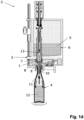
- FIG. 3 shows a longitudinal section through a further embodiment of a gas valve for use in the filling element of FIGS. 1 a - 1 e.
- FIGS. 1 a - 1 e show longitudinal sections through a filling element 1 at different stages of a filling process.
- the filling element 1 is arranged at a transport element 2 of a filling system 3 , of which only a section is shown here.
- the filling element 1 is connected, preferably for the duration of the filling process, to the container 4 that is intended to be filled with a fluid filling material 5 , which is provided from a tank 6 .
- the fluid filling material 5 encompasses any type of liquid that can be filled into containers 4 .
- the illustrated filling element 1 and the filling method are particularly useful for filling containers 4 with beverages, predominantly beverages that have been carbonated with carbon dioxide.
- the container 4 is shown as a bottle, the filling element 1 and the associated filling process are also well-suited, with slight, for other containers, such as cans or beakers.
- the liquid channel 7 connects to the tank 6 and ends in a discharge opening 9 .
- the discharge opening 9 faces the container 4 .
- a liquid valve 8 along the liquid channel 7 opens to allow filling material 5 to enter the container 4 .
- the gas channel 10 conveys gases that have served a variety of functions, such as a flushing gas, a pressurizing gas, and return gas that is displaced from the container 4 during filling thereof.
- gases that have served a variety of functions, such as a flushing gas, a pressurizing gas, and return gas that is displaced from the container 4 during filling thereof.
- Some embodiments feature plural gas channels 10 , each of which carries a different gas.
- the gas channel 10 comprises a gas opening 11 .
- the gas opening 11 extends into the container's interior 12 .
- the gas opening 11 does not extend into the container 4 but nevertheless faces it so that gas can enter the container 4 .
- a gas valve 13 along the gas channel 10 switches between the states of being opened, being closed, and being partially open.
- the filling process begins with the transport element 2 receiving the container 4 from an inlet star and connecting it to the filling element 1 .
- the container 4 is sealed tightly against the filling element.
- other filling processes do not require a tight seal.
- the filling process continues with the liquid valve 8 and the gas valve 13 both being closed.
- the container 4 is then exposed to a vacuum 14 , thereby removing any residual gas in the container 4 .
- FIG. 1 b shows a flushing step that includes partially opening the gas valve 13 . This permits a flushing gas, which is typically carbon dioxide, to dry any filling material residue still present in the gas channel 10 . The vacuum 14 is then used to suck any flushing gas flowing into the container 4 .
- a flushing gas which is typically carbon dioxide
- FIG. 1 c shows the next step, which is to pressurize the container 4 with a pressurizing gas, such as carbon dioxide. This is carried out by fully opening the gas valve 13 . To prevent this pressurizing gas from being sucked out of the container 4 , it is useful to also close a vacuum valve 15 , thus disconnecting the vacuum source 14 . As a result, pressure builds within the container 4 .
- a pressurizing gas such as carbon dioxide
- the next step is to introduce the actual liquid filling-material, as shown in FIG. 1 d .
- the liquid filling-material is introduced against the pressure of the pressurizing gas.
- the gas channel 10 plays the role of a return gas channel that can convey return gas as the filling material displaces it from the container.
- the liquid valve 8 is opened and the gas valve 13 is, at first, almost completely opened. This permits rapid outflow of the pressurizing gas from the container and thus rapid inflow of liquid filling-material into the container 4 .
- the next step is to slow down the filling as the desired filling height is reached. This provides a sensor that senses the filling height with enough time to make an accurate measurement and send an appropriate signal to stop filling.
- This deceleration step includes closing or choking the gas valve 13 , thus reducing the rate at which return gas leaves the container. This slows down the rate at which filling material can enter.
- a variety of ways are used to measure the filling height. These include an optical sensor or a hollow probe near the gas opening 11 .
- An alternative method is to use the Trinox process, in which a container continues to be filled until the liquid filling-material 5 reaches the gas opening 11 . When this happens, the gas opening 11 becomes submerged. As a result, no more return gas can escape. This halts the filling process.
- a sensor in the gas channel 10 recognizes the rising filling material 5 and determines that the filling height has been reached.
- liquid valve 8 closes and the gas valve 13 also closes.
- a pressure-equalization valve 16 relieves pressure in the container 4 .
- the container 4 When filling is complete, the container 4 is separated from the filling element and transferred to an outlet star for transport to a subsequent container-treatment machine.
- FIGS. 2 a - 2 e show the gas valve 13 in stages corresponding to those in FIGS. 1 a - 1 e.
- the gas valve 13 is shown in its closed position.
- the gas valve 13 includes a gas-valve tube 17 with a seal seat 19 .
- a gas-valve needle 18 which moves relative to the gas-valve tube 17 , has a sealing surface 20 and a choke 21 separated by a shaft 24 .
- the seal seat 19 eventually engages the sealing surface 20 and closes the gas valve 13 .
- the slot 23 is an annular region that surrounds the choke 21 .
- the shaft 24 meanwhile, lies in the construction 22 . Since the shaft's diameter is smaller than that of the choke 21 , the flow resistance that arises from having the shaft 24 at the constriction 22 is somewhat less than it would have been had the choke 21 been at the constriction 22 instead. This results in a medium flow resistance.
- FIG. 3 shown an alternative gas valve 13 that lacks the slot 23 .
- the gas valve 13 has more difficult attaining a medium flow resistance as shown in FIG. 2 e .
- the gas valve 13 shown in FIG. 3 is simpler and more economical to produce, while still retaining a partially-open state.
Landscapes
- Physics & Mathematics (AREA)
- Fluid Mechanics (AREA)
- Filling Of Jars Or Cans And Processes For Cleaning And Sealing Jars (AREA)
Abstract
Description
Claims (19)
Applications Claiming Priority (3)
| Application Number | Priority Date | Filing Date | Title |
|---|---|---|---|
| DE102018127592.7A DE102018127592B4 (en) | 2018-11-06 | 2018-11-06 | Filling element, filling system and method for filling containers |
| DE102018127592.7 | 2018-11-06 | ||
| PCT/EP2019/077017 WO2020094307A1 (en) | 2018-11-06 | 2019-10-07 | Filling element, filling system and method for filling containers |
Publications (2)
| Publication Number | Publication Date |
|---|---|
| US20210339997A1 US20210339997A1 (en) | 2021-11-04 |
| US11649151B2 true US11649151B2 (en) | 2023-05-16 |
Family
ID=68172204
Family Applications (1)
| Application Number | Title | Priority Date | Filing Date |
|---|---|---|---|
| US17/285,380 Active 2039-11-16 US11649151B2 (en) | 2018-11-06 | 2019-10-07 | Filling element, filling system, and method for filling containers |
Country Status (5)
| Country | Link |
|---|---|
| US (1) | US11649151B2 (en) |
| EP (1) | EP3877318A1 (en) |
| CN (1) | CN113039150B (en) |
| DE (1) | DE102018127592B4 (en) |
| WO (1) | WO2020094307A1 (en) |
Cited By (1)
| Publication number | Priority date | Publication date | Assignee | Title |
|---|---|---|---|---|
| US20220063979A1 (en) * | 2018-12-21 | 2022-03-03 | Gea Procomac S.P.A. | Filling device for filling a receptacle and process for the sanitisation thereof |
Families Citing this family (6)
| Publication number | Priority date | Publication date | Assignee | Title |
|---|---|---|---|---|
| US11047504B2 (en) * | 2018-06-06 | 2021-06-29 | Federal Mfg. Llc | Filling machine including two-stage actuator for filling valve |
| DE102022102536A1 (en) | 2022-02-03 | 2023-08-03 | Khs Gmbh | Filling machine and method for filling containers using a filling machine |
| DE102022102540A1 (en) | 2022-02-03 | 2023-08-03 | Khs Gmbh | Filling machine and method for filling containers using a filling machine |
| DE102022102553A1 (en) | 2022-02-03 | 2023-08-03 | Khs Gmbh | Filling machine and method for filling containers using a filling machine |
| DE102022102522A1 (en) | 2022-02-03 | 2023-08-03 | Khs Gmbh | Filling tank and filling machine |
| DE102022102530A1 (en) | 2022-02-03 | 2023-08-03 | Khs Gmbh | Filling machine with probe for filling level determination |
Citations (11)
| Publication number | Priority date | Publication date | Assignee | Title |
|---|---|---|---|---|
| US4452689A (en) * | 1982-07-02 | 1984-06-05 | Standard Oil Company (Indiana) | Huff and puff process for retorting oil shale |
| DE3807046A1 (en) | 1988-03-04 | 1989-10-12 | Seitz Enzinger Noll Masch | METHOD AND DEVICE FOR FILLING CARBONIC LIQUIDS, IN PARTICULAR DRINKS, UNDER BACK PRESSURE IN VESSELS OR THE LIKE. |
| US6213169B1 (en) * | 1998-04-27 | 2001-04-10 | Khs Maschinen- Und Anlagenbau Ag | Single-chamber filling system |
| US20050241726A1 (en) * | 2004-04-10 | 2005-11-03 | Ludwig Clusserath | Beverage bottling plant for filling bottles with a liquid beverage, having a filling machine with a rotary construction for filling bottles with a liquid beverage |
| DE60307504T2 (en) | 2002-12-04 | 2007-03-15 | Sidel Participations | METHOD AND DEVICE FOR CONTROLLING THE FILLING PROCESS OF A LIQUID INTO A CONTAINER |
| DE102013102611A1 (en) | 2013-03-14 | 2014-09-18 | Khs Gmbh | Method for rinsing containers |
| US20160152458A1 (en) * | 2013-07-09 | 2016-06-02 | Khs Gmbh | Filling system and method for the treatment of containers with a process gas |
| WO2016169925A1 (en) * | 2015-04-21 | 2016-10-27 | Khs Gmbh | Filling element assembly and filling machine |
| DE102015118612A1 (en) * | 2015-10-30 | 2017-05-04 | Krones Ag | Device for filling containers with a filling product |
| WO2019228805A1 (en) | 2018-05-30 | 2019-12-05 | Khs Gmbh | Filling system for filling containers with a liquid filling material, and filling machine |
| US10730734B2 (en) * | 2015-09-30 | 2020-08-04 | Krones Ag | Device for filling a container with a carbonated filling product |
Family Cites Families (7)
| Publication number | Priority date | Publication date | Assignee | Title |
|---|---|---|---|---|
| DE1216722B (en) | 1963-03-21 | 1966-05-12 | Brauerei Und Kellereimaschinen | Device for controlling a filling organ without a filling tube for bottle filling machines |
| DE3731759A1 (en) | 1987-09-22 | 1989-03-30 | Orthmann & Herbst | FUEL ORGAN FOR DRINKING FUEL DEVICES |
| CN1750993A (en) * | 2003-02-19 | 2006-03-22 | 可口可乐公司 | System and method for aseptically filling packages with liquid products |
| DE10359312B4 (en) * | 2003-12-17 | 2016-02-25 | Khs Gmbh | Filling machine for filling containers |
| EP1731426B1 (en) * | 2005-06-10 | 2007-08-22 | INDAG Gesellschaft für Industriebedarf mbH & Co. Betriebs KG | Method and apparatus for filling liquids into plastic bags with a spout |
| CN202880825U (en) * | 2012-11-12 | 2013-04-17 | 南京乐惠轻工装备制造有限公司 | Electronic liquid-filling device |
| DE102015111374A1 (en) * | 2015-07-14 | 2017-01-19 | Krones Ag | Apparatus and method for introducing a gas into a container to be filled with a filling product |
-
2018
- 2018-11-06 DE DE102018127592.7A patent/DE102018127592B4/en active Active
-
2019
- 2019-10-07 WO PCT/EP2019/077017 patent/WO2020094307A1/en not_active Ceased
- 2019-10-07 EP EP19784035.8A patent/EP3877318A1/en active Pending
- 2019-10-07 CN CN201980073024.0A patent/CN113039150B/en active Active
- 2019-10-07 US US17/285,380 patent/US11649151B2/en active Active
Patent Citations (11)
| Publication number | Priority date | Publication date | Assignee | Title |
|---|---|---|---|---|
| US4452689A (en) * | 1982-07-02 | 1984-06-05 | Standard Oil Company (Indiana) | Huff and puff process for retorting oil shale |
| DE3807046A1 (en) | 1988-03-04 | 1989-10-12 | Seitz Enzinger Noll Masch | METHOD AND DEVICE FOR FILLING CARBONIC LIQUIDS, IN PARTICULAR DRINKS, UNDER BACK PRESSURE IN VESSELS OR THE LIKE. |
| US6213169B1 (en) * | 1998-04-27 | 2001-04-10 | Khs Maschinen- Und Anlagenbau Ag | Single-chamber filling system |
| DE60307504T2 (en) | 2002-12-04 | 2007-03-15 | Sidel Participations | METHOD AND DEVICE FOR CONTROLLING THE FILLING PROCESS OF A LIQUID INTO A CONTAINER |
| US20050241726A1 (en) * | 2004-04-10 | 2005-11-03 | Ludwig Clusserath | Beverage bottling plant for filling bottles with a liquid beverage, having a filling machine with a rotary construction for filling bottles with a liquid beverage |
| DE102013102611A1 (en) | 2013-03-14 | 2014-09-18 | Khs Gmbh | Method for rinsing containers |
| US20160152458A1 (en) * | 2013-07-09 | 2016-06-02 | Khs Gmbh | Filling system and method for the treatment of containers with a process gas |
| WO2016169925A1 (en) * | 2015-04-21 | 2016-10-27 | Khs Gmbh | Filling element assembly and filling machine |
| US10730734B2 (en) * | 2015-09-30 | 2020-08-04 | Krones Ag | Device for filling a container with a carbonated filling product |
| DE102015118612A1 (en) * | 2015-10-30 | 2017-05-04 | Krones Ag | Device for filling containers with a filling product |
| WO2019228805A1 (en) | 2018-05-30 | 2019-12-05 | Khs Gmbh | Filling system for filling containers with a liquid filling material, and filling machine |
Non-Patent Citations (2)
| Title |
|---|
| DE102015118612A1—English Translation (Year: 2017). * |
| WO2016207006A1—English Translation (Year: 2016). * |
Cited By (2)
| Publication number | Priority date | Publication date | Assignee | Title |
|---|---|---|---|---|
| US20220063979A1 (en) * | 2018-12-21 | 2022-03-03 | Gea Procomac S.P.A. | Filling device for filling a receptacle and process for the sanitisation thereof |
| US11760617B2 (en) * | 2018-12-21 | 2023-09-19 | Gea Procomac S.P.A. | Filling device for filling a receptacle and process for the sanitisation thereof |
Also Published As
| Publication number | Publication date |
|---|---|
| EP3877318A1 (en) | 2021-09-15 |
| CN113039150A (en) | 2021-06-25 |
| DE102018127592B4 (en) | 2020-07-16 |
| US20210339997A1 (en) | 2021-11-04 |
| WO2020094307A1 (en) | 2020-05-14 |
| CN113039150B (en) | 2023-08-29 |
| DE102018127592A1 (en) | 2020-05-07 |
Similar Documents
| Publication | Publication Date | Title |
|---|---|---|
| US11649151B2 (en) | Filling element, filling system, and method for filling containers | |
| EP2588403B1 (en) | Tap for beverage dispensing devices from receptacles such as bottles and the like | |
| EP3176126B1 (en) | A filling device for a filling machine | |
| EP1908726B1 (en) | Isobaric rotary filling machine with CIP-provision for the cleaning of every filling-valve | |
| CN106455517B (en) | Milking system | |
| US9205937B2 (en) | Filling element, method and filling system for filling containers | |
| US6790346B2 (en) | Cyclone separator suitable for variable fluid flow rates | |
| US11655132B2 (en) | Apparatus for filling a container with a filling product | |
| JPH05305996A (en) | Method for filling liquid-filled products in bottles or similar containers and apparatus for carrying out this method | |
| JP2009537401A (en) | Method and apparatus for controlling foaming of a charge placed in a bottle or equivalent container | |
| JP5492687B2 (en) | Device for filling a container with liquid | |
| US10029901B2 (en) | Filling element, filling system and method for filling containers | |
| EP3009394A1 (en) | Beverage filling method | |
| US6083306A (en) | Separator and discharger device for waste fluids in dental aspiration apparatus | |
| EP3468910B1 (en) | Device and method for filling containers with a liquid, in particular for bottling | |
| CN113039440B (en) | Automatic analysis device | |
| US20180043042A1 (en) | Method and treatment station for heating and sterilized kegs in particular reuseable kegs | |
| JP2017206299A (en) | Filling machine, filling method, and filling system | |
| US8146611B2 (en) | Method and apparatus for cleaning ophthalmic lenses | |
| US2081339A (en) | Liquid storage tank | |
| EP3473588A1 (en) | Device and method for filling receptacles with a pourable product under pressure | |
| CN112423633A (en) | Outflow nozzle, beverage preparation machine and method for cleaning an outflow nozzle of a beverage preparation machine | |
| EP1020163B1 (en) | A separator and discharger device for waste fluids in dental aspiration apparatus | |
| JP2764777B2 (en) | Deaerator for filling device | |
| EP3473589A1 (en) | Filling machine and method for filling receptacles with a pourable product under pressure |
Legal Events
| Date | Code | Title | Description |
|---|---|---|---|
| FEPP | Fee payment procedure |
Free format text: ENTITY STATUS SET TO UNDISCOUNTED (ORIGINAL EVENT CODE: BIG.); ENTITY STATUS OF PATENT OWNER: LARGE ENTITY |
|
| AS | Assignment |
Owner name: KHS GMBH, GERMANY Free format text: ASSIGNMENT OF ASSIGNORS INTEREST;ASSIGNORS:CLUESSERATH, LUDWIG;KRULITSCH, DIETER-RUDOLF;LOHNER, ANDREAS;AND OTHERS;SIGNING DATES FROM 20210419 TO 20210422;REEL/FRAME:056255/0353 |
|
| STPP | Information on status: patent application and granting procedure in general |
Free format text: DOCKETED NEW CASE - READY FOR EXAMINATION |
|
| STPP | Information on status: patent application and granting procedure in general |
Free format text: NON FINAL ACTION MAILED |
|
| STPP | Information on status: patent application and granting procedure in general |
Free format text: RESPONSE TO NON-FINAL OFFICE ACTION ENTERED AND FORWARDED TO EXAMINER |
|
| STPP | Information on status: patent application and granting procedure in general |
Free format text: FINAL REJECTION MAILED |
|
| STPP | Information on status: patent application and granting procedure in general |
Free format text: RESPONSE AFTER FINAL ACTION FORWARDED TO EXAMINER |
|
| STPP | Information on status: patent application and granting procedure in general |
Free format text: AMENDMENT AFTER NOTICE OF APPEAL |
|
| STCV | Information on status: appeal procedure |
Free format text: NOTICE OF APPEAL FILED |
|
| STPP | Information on status: patent application and granting procedure in general |
Free format text: RESPONSE TO NON-FINAL OFFICE ACTION ENTERED AND FORWARDED TO EXAMINER |
|
| STCF | Information on status: patent grant |
Free format text: PATENTED CASE |