US11648147B2 - Instrument to prepare an intra-uterine device for insertion - Google Patents
Instrument to prepare an intra-uterine device for insertion Download PDFInfo
- Publication number
- US11648147B2 US11648147B2 US16/936,613 US202016936613A US11648147B2 US 11648147 B2 US11648147 B2 US 11648147B2 US 202016936613 A US202016936613 A US 202016936613A US 11648147 B2 US11648147 B2 US 11648147B2
- Authority
- US
- United States
- Prior art keywords
- iud
- downfolding
- graduated tube
- instrument
- open channel
- Prior art date
- Legal status (The legal status is an assumption and is not a legal conclusion. Google has not performed a legal analysis and makes no representation as to the accuracy of the status listed.)
- Active, expires
Links
- 238000003780 insertion Methods 0.000 title claims abstract description 9
- 230000037431 insertion Effects 0.000 title claims abstract description 9
- 210000004291 uterus Anatomy 0.000 claims abstract description 22
- 230000015572 biosynthetic process Effects 0.000 claims abstract description 16
- 238000000034 method Methods 0.000 claims description 16
- 229920001169 thermoplastic Polymers 0.000 claims description 9
- 239000004416 thermosoftening plastic Substances 0.000 claims description 9
- 230000000295 complement effect Effects 0.000 claims description 3
- 210000003811 finger Anatomy 0.000 claims description 3
- 230000000284 resting effect Effects 0.000 claims description 3
- 210000003813 thumb Anatomy 0.000 claims description 3
- 239000003292 glue Substances 0.000 claims description 2
- 238000005259 measurement Methods 0.000 description 6
- 210000003679 cervix uteri Anatomy 0.000 description 3
- RYGMFSIKBFXOCR-UHFFFAOYSA-N Copper Chemical compound [Cu] RYGMFSIKBFXOCR-UHFFFAOYSA-N 0.000 description 2
- 238000010276 construction Methods 0.000 description 2
- 229910052802 copper Inorganic materials 0.000 description 2
- 239000010949 copper Substances 0.000 description 2
- 238000004806 packaging method and process Methods 0.000 description 2
- 238000002360 preparation method Methods 0.000 description 2
- 239000003433 contraceptive agent Substances 0.000 description 1
- 230000002254 contraceptive effect Effects 0.000 description 1
- 229940124566 female contraceptive agent Drugs 0.000 description 1
- 239000003037 female contraceptive agent Substances 0.000 description 1
- 230000014509 gene expression Effects 0.000 description 1
- 208000014674 injury Diseases 0.000 description 1
- 230000008733 trauma Effects 0.000 description 1
Images


Classifications
-
- A—HUMAN NECESSITIES
- A61—MEDICAL OR VETERINARY SCIENCE; HYGIENE
- A61F—FILTERS IMPLANTABLE INTO BLOOD VESSELS; PROSTHESES; DEVICES PROVIDING PATENCY TO, OR PREVENTING COLLAPSING OF, TUBULAR STRUCTURES OF THE BODY, e.g. STENTS; ORTHOPAEDIC, NURSING OR CONTRACEPTIVE DEVICES; FOMENTATION; TREATMENT OR PROTECTION OF EYES OR EARS; BANDAGES, DRESSINGS OR ABSORBENT PADS; FIRST-AID KITS
- A61F6/00—Contraceptive devices; Pessaries; Applicators therefor
- A61F6/06—Contraceptive devices; Pessaries; Applicators therefor for use by females
- A61F6/14—Contraceptive devices; Pessaries; Applicators therefor for use by females intra-uterine type
- A61F6/18—Inserters or removers
-
- A—HUMAN NECESSITIES
- A61—MEDICAL OR VETERINARY SCIENCE; HYGIENE
- A61F—FILTERS IMPLANTABLE INTO BLOOD VESSELS; PROSTHESES; DEVICES PROVIDING PATENCY TO, OR PREVENTING COLLAPSING OF, TUBULAR STRUCTURES OF THE BODY, e.g. STENTS; ORTHOPAEDIC, NURSING OR CONTRACEPTIVE DEVICES; FOMENTATION; TREATMENT OR PROTECTION OF EYES OR EARS; BANDAGES, DRESSINGS OR ABSORBENT PADS; FIRST-AID KITS
- A61F6/00—Contraceptive devices; Pessaries; Applicators therefor
- A61F6/06—Contraceptive devices; Pessaries; Applicators therefor for use by females
- A61F6/14—Contraceptive devices; Pessaries; Applicators therefor for use by females intra-uterine type
- A61F6/142—Wirelike structures, e.g. loops, rings, spirals
- A61F6/144—Wirelike structures, e.g. loops, rings, spirals with T-configuration
Definitions
- the present invention relates to intra-uterine device, particularly to an instrument which is to load and insert intra-uterine device and the process of loading and inserting the intra-uterine device hygienically.
- Intra-uterine device (herein after abbreviated as IUD) is a long- or medium-term contraceptive which is placed in the uterus of female. Most commonly available IUDs are in the shape of the English letter “T” since this shape is found appropriate to the shape of uterus.
- IUDs While the IUDs are required to be in the shape of “T”, they cannot be inserted in this form as the opening of the cervix is small. Arms forming “T” of IUD are folded either upwards or downwards so that IUD can be contained in the opening of a narrow tube which then can be inserted in the uterus. This process of folding the IUD so that the instrument is ready to insert is known as loading or preparing the IUD.
- Loading or preparing of IUD needs to be done minutes before it is required to be inserted in uterus, and if done earlier, or if supplied duly loaded, then the IUD shall not return to the desired “T” shape in uterus, and shall not work effectively. Due to this requirement, the process of loading has to be performed by service providers just prior to inserting and placing IUD in uterus.
- Up-folding IUDs and down-folding IUD have a significant difference in their preparation.
- Upfolding IUDs implies that arms forming “T” are together while stem of IUD is below folded arms. This may be easily understood from FIGS. 1A to 3B of Patent US005785053A.
- Patent application US2013/0014762(A1) also comprehensively covers an upfolding IUD.
- Down-folding implies that arms forming “T” as well as stem of IUD are together. This may be easily understood from FIGS. 7 and 9 of U.S. Pat. No. 4,143,656.
- an upfolding IUD is easier to load and difficult to place in uterus, while a downfolding IUD is relatively more difficult to load and relatively easier to place.
- Patent application Ser. No. 15/745,579 discloses an instrument to load a downfold IUD without human maneuvering.
- Present invention effectively and economically addresses loading or preparation of downfolding IUDs for subsequent insertion and placement in uterus.
- the objective is to invent an instrument to load or prepare the intra-uterine device hygienically.
- Another objective is to invent a simple instrument to load or prepare the intra-uterine device which is downfoldable.
- Yet another objective is to invent an instrument which is capable of loading the intra uterine device in a consistent manner.
- Yet another objective is to invent an instrument that causes minimal insertion trauma to woman.
- Yet another objective is to invent an instrument which is economical and effective.
- the instrument according to present invention comprises a downfolding device, a graduated tube, a push rod, a stopper, and an intra-uterine device generally known as an IUD, encased in a transparent pouch.
- the IUD is essentially in a “T” shape, comprising a molded frame having a metallic envelope/wire wrapped around a stem, preferably with a sleeve on each of a pair of arms.
- the sleeve is generally made of medical grade copper.
- the downfolding device has a fence and an open channel, spaced by a platform, on a base.
- An external side of the fence has a depression on either side, a concave, and generally complementary to a convex shape of human thumb and human fingers and therefore acts as a receptacle; consequently a service provider can hold the downfolding device firmly and which facilitates easy and secure loading of IUD into the graduated tube.
- An internal side of the fence has a converging opening, turning into a narrow zone and ending into a well having a depth.
- the narrow zone has a projecting ridge on either side, leaving a clear passage.
- the well has an orienting step on either side.
- the open channel has a circular orifice having a sector of angle measure at least 220°.
- the circular orifice merges with a pair of divergent walls, having an exit opening that is initially marginally less than an external diameter of the graduated tube.
- a root thickness of the base in-between the open channel is minimal. Consequently, the exit opening increases by the base flexing and or when a lower surface of the base is devoid of a firm support underneath.
- An upper enveloping surface all over the downfolding device is a smoothened surface devoid of sharp projection.
- the graduated tube has an internal diameter of a far-end opening of the graduated tube just sufficient to capture the stem and both arms of the IUD in substantially a downward triangular formation.
- the downward triangular formation is attainable by entering a downfolded IUD in a graduated tube from the stem end such that the arm ends subsequently enter the graduated tube with a minimal force such that the arm ends are inside a graduated tube up to the step of the sleeve on the IUD.
- the graduated tube is provided with measurement marks so that the stopper can be conveniently adjusted at precisely required position without needing measurement device and while the instrument is in the transparent pouch.
- the IUD is parked in the downfolding device with its arms resting at the platform and the stem passing through the open channel of the downfolding device.
- the instrument is packaged in sterile environment in the transparent pouch with a transparent cover and a back. As a variation, the packaged instrument is sterilized after packaging.
- the transparent pouch is made of a thermoplastic sheath of thickness such that the downfolding device when gripped firmly from an outside of the transparent cover of the transparent pouch can be gripped adequately.
- the upper enveloping surface all over the downfolding device being a smoothened surface devoid of sharp projection, facilitates such ripping without the thermoplastic sheath getting punctured or torn consequently.
- a shear strength of the thermoplastic sheath withstands expected transportation and storage abuse.
- the transparent cover is partially separated from the back of the transparent pouch, only to be able to access and hold the near end opening of graduated tube.
- the downfolding device is firmly held by one hand from outside the transparent cover while the graduated tube is pushed in.
- the IUD As the graduated tube starts pushing the IUD, the IUD has to negotiate its shape due to the converging opening in the downfolding device. Consequently, the arms of the IUD start folding towards the stem end, such partially folded arms.
- the downfolding device guides the graduated tube through towards the well consequent to the open channel.
- the depth of the well of the well of the downfolding device is such that, as the graduated tube continues to push the IUD, there comes a situation when a fundal end of the IUD gets stopped by the of the well, and the arms of the IUD become substantially in the same orientation as the stem of the IUD.
- the orienting step ensures that the arms always fold above the orienting step in accordance with the downward triangular formation, and an upward triangular formation is prevented.
- the arms are captured in the far-end opening by manual maneuvering of the graduated tube.
- the maneuvering essentially involves partially withdrawing the graduated tube backwards out of the open channel of the downloading device, angularly lifting the graduated tube 16 above the open channel, slightly turning it axially on either side so as to make the ends of the arm of IUD enter the far-end opening of graduated tub and finally pushing up the graduated tube again.
- the graduated tube is axially turned substantially by an angle of about 90 degrees, particularly 85 to 95 degrees on either side so that it can come out from the top of the downfolding device, clear of the projecting ridge.
- the stopper is adjusted to the required location in accordance with the sounding measurement carried out independently, as is known.
- the Instrument is now fully withdrawn from the pouch and inserted in uterus of the female till the stopper touches the external orifice of cervix of woman.
- the graduated tube is withdrawn, while the pushrod is kept steady, thereby first releasing the arms of the IUD and then the stem of the IUD from the graduated tube.
- the folded arms of IUD return to its original shape of the arms.
- the graduated tube is withdrawn out of the uterus. This two-stage withdrawal ensures that IUD is not disturbed by the withdrawal of the graduated tube.
- Construction of the converging opening of the downfolding device is possible in different ways, by different radii or by providing a straight but angular slant, conceptually and eventually leading to folding of the arms of IUD at it is pushed inside the downfolding device.
- the maneuvering need not involve partially withdrawing of the graduated tube backwards out of the open channel of the downloading device, and the graduated tube may still be angularly lifted above the open channel, since the root thickness of the base in-between the open channel is minimal and consequently, the exit opening increases by the base flexing and or when a lower surface of the base is devoid of a firm support underneath.
- FIG. 1 is a front view of an apparatus as per present invention.
- FIG. 2 is a front view of a downfoldable IUD.
- FIG. 3 is a perspective view of a downfolding device as per present invention.
- FIG. 4 is a top view and a sectional side view of the downfolding device.
- FIG. 5 A is a front view of the downfolding device while FIG. 5 B is another front view with its base flexed.
- FIG. 6 is a front view of a downfolded IUD with arms downfolded.
- FIG. 7 is a front view of a graduated tube.
- FIG. 8 is a partial front view of a prepared IUD.
- FIG. 9 A is a sectional top view of the graduated tube with downfolded IUD therein in the downward triangular formation, and the graduated tube before loading an IUD, while FIG. 9 B is a similar sectional top view in the upward triangular formation.
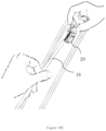
- FIG. 10 A- 10 E show steps, in perspective view, of preparing the instrument for insertion of the IUD, while FIG. 10 F is a sectional side view.
- FIG. 11 is a representative view of a transparent pouch.
- FIG. 12 is a representative top view of a downfolding device and the IUD in two different shapes while loading.
- FIG. 13 shows a simplified uterus with IUD inserted.
- FIG. 14 shows a simplified uterus with IUD placed.
- the instrument 10 comprises a downfolding device 20 , a graduated tube 16 , a push rod 17 , a stopper 15 , and an IUD 30 , encased in a transparent pouch 60 .
- the IUD 30 is essentially in a “T” shape, comprising a moulded frame 35 having a metallic envelope/wire 49 wrapped around a stem 33 , preferably with a sleeve 26 on each of a pair of arms 32 .
- the sleeve 26 is generally made of medical grade copper.
- the downfolding device 20 has a fence 21 and an open channel 29 , spaced by a platform 34 , on a base 37 .
- An external side 38 A of the fence 21 has a depression 41 on either side, a concave, and generally complementary to a convex shape of human thumb and human fingers and therefore acts as a receptacle; consequently a service provider can hold the downfolding device 20 firmly and which facilitates easy and secure loading of IUD into the graduated tube 16 .
- An internal side 38 B of the fence 21 has a converging opening 23 A, turning into a narrow zone 23 B and ending into a well 24 having a depth 24 A.
- the narrow zone 23 B has a projecting ridge 27 on either side, leaving a clear passage 27 A.
- the well 24 has an orienting step 61 on either side.
- the well 24 is closed from a far end 42 .
- a proximal end 43 of the converging opening has, on either side, an inclined wall 44 with a local relief 45 , for accommodating a step 32 S in the arms 32 of the IUD 30 which may be due to the sleeve 26 , and merging with the internal side 38 B of the fence 21 .
- a diametric dimension 24 B of well 24 above the orienting step 61 , is commensurate with an envelope dimension 38 of the IUD 30 when downfolded.
- the open channel 29 has a circular orifice 46 having a sector of angle measure 46 A at least 220°.
- the circular orifice 46 merges with a pair of divergent walls 47 , having an exit opening 48 that is initially marginally less than an external diameter 22 B of the graduated tube 16 .
- a root thickness 37 B of the base 37 in-between the open channel 29 is minimal. Consequently, the exit opening 48 increases by the base 37 flexing and or when a lower surface 37 A of the base 37 is devoid of a firm support underneath as particularly shown in FIG. 5 B .
- An upper enveloping surface 28 all over the downfolding device 20 is a smoothened surface devoid of sharp projection.
- a width 27 B of the clear passage 27 A is comparable to a height 22 C of a triangle ( FIG. 9 A ) formed at a far end of the graduated tube 16 carrying a prepared IUD, as described below.
- the graduated tube 16 has an internal diameter 22 D of a far-end opening 22 a of the graduated tube 16 just sufficient to capture the stem 33 and both arms 32 of IUD in substantially a downward triangular formation 51 .
- the downward triangular formation 51 is attainable by entering the IUD 30 with a downfolded arms 32 n in a graduated tube 16 from the stem end 36 such that the arm ends 31 subsequently enter the graduated tube 16 with a minimal force such that the arm ends 31 are inside a graduated tube 16 up to the step 32 S of the sleeve 26 on the IUD 30 .
- the graduated tube 16 is provided with measurement marks 14 so that the stopper 15 can be conveniently adjusted at precisely required position without needing measurement device and while the instrument 10 is in the transparent pouch 60 .
- the IUD 30 is parked in the downfolding device 20 with its arms 32 resting at the platform 34 and the stem 33 passing through the open channel 29 of the downfolding device 20 .
- the IUD 30 is parked in the downfolding device 20 in the “T” shape which it is required to maintain inside uterus 50 .
- the downfolding device 20 is firmly disposed in a prescribed place in the transparent pouch 60 .
- the prescribed place in the transparent pouch 60 is ensured by a tight fit of the downloading device 20 in the transparent pouch 60 ; or by thermally shrinking the thermoplastic sheath 39 around the downfolding device 20 .
- the prescribed place in the transparent pouch 60 is by a glue disposed between the base 37 of the downfolding device 20 and the back 40 of the transparent pouch 60 .
- the instrument 10 is packaged in sterile environment in the transparent pouch with a transparent cover 39 and a back 40 .
- the packaged instrument 10 is sterilized after packaging.
- the transparent pouch 60 is made of a thermoplastic sheath of thickness such that the downfolding device 20 when gripped firmly from an outside of the transparent cover 39 of the transparent pouch 60 can be gripped adequately.
- the upper enveloping surface 28 all over the downfolding device 20 being a smoothened surface devoid of sharp projection, facilitates such ripping without the thermoplastic sheath getting punctured or torn consequently.
- a shear strength of the thermoplastic sheath withstands expected transportation and storage abuse.
- FIG. 10 A- 10 E to start the process of loading, the transparent cover 39 is partially separated (not explicitly shown such in these views) from the back 40 of the transparent pouch 60 , only to be able to access and hold the near end opening 22 of graduated tube 16 .
- the downfolding device 20 is firmly held by one hand from outside the transparent cover 39 while the graduated tube 16 is pushed in.
- the transparent pouch 60 is firmly held instead of the downfolding device 20 .
- the IUD 30 As the graduated tube 16 starts pushing the IUD 30 , the IUD 30 has to negotiate its shape due to the converging opening 23 A in the downfolding device 20 . Consequently, the arms 32 of the IUD 30 start folding towards the stem end 36 , such partially folded arms 32 a ( FIG. 12 ). The downfolding device 20 guides the graduated tube 16 through towards the well 24 consequent to the open channel 29 .
- the depth of the well 24 A of the well 24 of the downfolding device 20 is such that, as the graduated tube 16 continues to push the IUD 30 , there comes a situation when a fundal end 32 F 30 F of the IUD 30 gets stopped by the end 24 C of the well 24 , and the arms 32 n of the IUD 30 become substantially in the same orientation as the stem 33 of IUD 30 .
- the orienting step 61 ensures that the arms 32 always fold above the orienting step 61 in accordance with the downward triangular formation 51 , and an upward triangular formation 52 is prevented ( FIG. 9 A, 9 B ).
- the arms 32 are captured in the far-end opening 22 a by manual maneuvering of the graduated tube 16 .
- the maneuvering essentially involves partially withdrawing the graduated tube 16 backwards out of the open channel 29 of the downloading device 20 , angularly lifting the graduated tube 16 above the open channel 29 , slightly turning it axially on either side so as to make the ends of the arm 32 n ( FIG. 12 ) of IUD 30 enter the far-end opening 22 a of graduated tube 16 and finally pushing up the graduated tube 16 again.
- the graduated tube 16 is axially turned substantially by about 90 degrees on either side so that it can come out from the top of the downfolding device 20 , clear of the projecting ridge 27 .
- the stopper 15 is adjusted to the required location 12 in accordance with the sounding measurement carried out independently, as is known.
- FIGS. 13 , 14 the Instrument 10 is now fully withdrawn from the pouch and inserted in uterus 50 of the female till stopper 15 touch the external orifice of cervix.
- the graduated tube 16 is withdrawn, while the pushrod 17 is kept steady, thereby first releasing the arms 32 n of the IUD 30 and then the stem 33 of the IUD 30 from the graduated tube 16 .
- the folded arms 32 n of IUD 30 return to its original shape of the arms 32 .
- the graduated tube 16 is withdrawn out of the uterus 50 . This two-stage withdrawal ensures that the IUD 30 is not disturbed by the withdrawal of the graduated tube 16 .
- Construction of the converging opening 23 A of the downfolding device 20 is possible in different ways, by different radii or by providing a straight but angular slant, conceptually and eventually leading to folding of the arms 32 of IUD 30 at it is pushed inside the downfolding device 20 .
- the maneuvering need not involve partially withdrawing of the graduated tube 16 backwards out of the open channel 29 of the downloading device 20 , and the graduated tube 16 may still be angularly lifted above the open channel 29 , since the root thickness 37 B of the base 37 in-between the open channel 29 is minimal and consequently, the exit opening 48 increases by the base 37 flexing and or when a lower surface 37 A of the base 37 is devoid of a firm support underneath.
Landscapes
- Health & Medical Sciences (AREA)
- Reproductive Health (AREA)
- Engineering & Computer Science (AREA)
- Biomedical Technology (AREA)
- Heart & Thoracic Surgery (AREA)
- Vascular Medicine (AREA)
- Life Sciences & Earth Sciences (AREA)
- Animal Behavior & Ethology (AREA)
- General Health & Medical Sciences (AREA)
- Public Health (AREA)
- Veterinary Medicine (AREA)
- Surgical Instruments (AREA)
Abstract
Description
Claims (8)
Applications Claiming Priority (2)
| Application Number | Priority Date | Filing Date | Title |
|---|---|---|---|
| IN201921030966 | 2019-07-31 | ||
| IN201921030966 | 2019-07-31 |
Publications (2)
| Publication Number | Publication Date |
|---|---|
| US20210030585A1 US20210030585A1 (en) | 2021-02-04 |
| US11648147B2 true US11648147B2 (en) | 2023-05-16 |
Family
ID=74258212
Family Applications (1)
| Application Number | Title | Priority Date | Filing Date |
|---|---|---|---|
| US16/936,613 Active 2040-10-31 US11648147B2 (en) | 2019-07-31 | 2020-07-23 | Instrument to prepare an intra-uterine device for insertion |
Country Status (1)
| Country | Link |
|---|---|
| US (1) | US11648147B2 (en) |
Families Citing this family (3)
| Publication number | Priority date | Publication date | Assignee | Title |
|---|---|---|---|---|
| WO2021102220A1 (en) * | 2019-11-21 | 2021-05-27 | Coopersurgical, Inc. | Packaging systems for implantable devices and related methods |
| WO2023278357A1 (en) * | 2021-06-29 | 2023-01-05 | Nicola Nasser | Applicator for cervical brachytherapy |
| USD1070085S1 (en) | 2022-03-17 | 2025-04-08 | Pregna International Limited | Intra-uterine inserter |
Citations (4)
| Publication number | Priority date | Publication date | Assignee | Title |
|---|---|---|---|---|
| US3797493A (en) * | 1970-11-20 | 1974-03-19 | E Saudek | Single use container, especially for pharmaceutical material |
| DE2506890B1 (en) * | 1975-02-12 | 1976-05-06 | Schering Ag | Assembly aid device for intrauterine device applicators |
| US4549652A (en) * | 1983-06-29 | 1985-10-29 | Piact | IUD Package |
| US5370129A (en) * | 1992-08-28 | 1994-12-06 | Db Inserters, Inc. | IUD inserting apparatus |
-
2020
- 2020-07-23 US US16/936,613 patent/US11648147B2/en active Active
Patent Citations (4)
| Publication number | Priority date | Publication date | Assignee | Title |
|---|---|---|---|---|
| US3797493A (en) * | 1970-11-20 | 1974-03-19 | E Saudek | Single use container, especially for pharmaceutical material |
| DE2506890B1 (en) * | 1975-02-12 | 1976-05-06 | Schering Ag | Assembly aid device for intrauterine device applicators |
| US4549652A (en) * | 1983-06-29 | 1985-10-29 | Piact | IUD Package |
| US5370129A (en) * | 1992-08-28 | 1994-12-06 | Db Inserters, Inc. | IUD inserting apparatus |
Also Published As
| Publication number | Publication date |
|---|---|
| US20210030585A1 (en) | 2021-02-04 |
Similar Documents
| Publication | Publication Date | Title |
|---|---|---|
| US11648147B2 (en) | Instrument to prepare an intra-uterine device for insertion | |
| US4549652A (en) | IUD Package | |
| US4106621A (en) | Combination needle cover and venipuncture device tray and method of using same | |
| US6457612B1 (en) | Sealable and manipulable pre-filled disposable pipette | |
| US4341211A (en) | Lubricating object applicator | |
| US4428370A (en) | Insertion unit for a vaginal diaphragm | |
| JPH10510444A (en) | Insertion device used to place intrauterine devices | |
| JP2863236B2 (en) | Ophthalmic instruments | |
| FR2499404A1 (en) | INSTRUMENT FACILITATING THE HOUSING OF AN INTRAUTERIN DEVICE IN A PLACEMENT TUBE | |
| EP3485854B1 (en) | Applicator device for a menstrual cup | |
| US4911158A (en) | Lens folding block | |
| RS63825B1 (en) | HYGIENIC DEVICE FOR COLLECTION OF MENSTRUAL FLUID | |
| JP2023067971A (en) | Arrangement for intrauterine system and inserter therefor | |
| US20180207023A1 (en) | Apparatus for loading, insertion and placement of an intrauterine contraceptive devce and process thereof | |
| US6123683A (en) | Pill delivery apparatus | |
| US12485037B2 (en) | Packaging systems for implantable devices and related methods | |
| US4004582A (en) | Intracervical contraceptive device | |
| EP4161414B1 (en) | System for assisting conception | |
| US11963904B2 (en) | Instrument to prepare and safely place an intra-uterine device | |
| EP0080638A1 (en) | Intrauterine contraceptive loading device and method | |
| CN114144222A (en) | Drug delivery and administration device | |
| US11622880B2 (en) | Self-applicable condom | |
| US1015952A (en) | Hypodermic syringe. | |
| US20230127093A1 (en) | Single-use instrument to prepare and safely place an intra-uterine device | |
| SE527963C2 (en) | Lubricant applicator for assisting insertion of instrument into urinary tube, comprises squeezable lubricant vessel connected to tube with outlet opening |
Legal Events
| Date | Code | Title | Description |
|---|---|---|---|
| AS | Assignment |
Owner name: PREGNA INTERNATIONAL LIMITED, INDIA Free format text: ASSIGNMENT OF ASSIGNORS INTEREST;ASSIGNOR:TAPARIA, MUKUL;REEL/FRAME:053290/0333 Effective date: 20200722 |
|
| FEPP | Fee payment procedure |
Free format text: ENTITY STATUS SET TO UNDISCOUNTED (ORIGINAL EVENT CODE: BIG.); ENTITY STATUS OF PATENT OWNER: SMALL ENTITY |
|
| FEPP | Fee payment procedure |
Free format text: ENTITY STATUS SET TO SMALL (ORIGINAL EVENT CODE: SMAL); ENTITY STATUS OF PATENT OWNER: SMALL ENTITY |
|
| STPP | Information on status: patent application and granting procedure in general |
Free format text: DOCKETED NEW CASE - READY FOR EXAMINATION |
|
| STPP | Information on status: patent application and granting procedure in general |
Free format text: NON FINAL ACTION MAILED |
|
| STPP | Information on status: patent application and granting procedure in general |
Free format text: RESPONSE TO NON-FINAL OFFICE ACTION ENTERED AND FORWARDED TO EXAMINER |
|
| STPP | Information on status: patent application and granting procedure in general |
Free format text: FINAL REJECTION MAILED |
|
| STPP | Information on status: patent application and granting procedure in general |
Free format text: RESPONSE AFTER FINAL ACTION FORWARDED TO EXAMINER |
|
| STPP | Information on status: patent application and granting procedure in general |
Free format text: ADVISORY ACTION MAILED |
|
| STPP | Information on status: patent application and granting procedure in general |
Free format text: DOCKETED NEW CASE - READY FOR EXAMINATION |
|
| STPP | Information on status: patent application and granting procedure in general |
Free format text: NON FINAL ACTION MAILED |
|
| STPP | Information on status: patent application and granting procedure in general |
Free format text: RESPONSE TO NON-FINAL OFFICE ACTION ENTERED AND FORWARDED TO EXAMINER |
|
| STCF | Information on status: patent grant |
Free format text: PATENTED CASE |