US11644016B2 - Metal plasma thruster cube - Google Patents
Metal plasma thruster cube Download PDFInfo
- Publication number
- US11644016B2 US11644016B2 US17/214,893 US202117214893A US11644016B2 US 11644016 B2 US11644016 B2 US 11644016B2 US 202117214893 A US202117214893 A US 202117214893A US 11644016 B2 US11644016 B2 US 11644016B2
- Authority
- US
- United States
- Prior art keywords
- electrode
- insulator
- trigger
- plasma
- cathode electrode
- Prior art date
- Legal status (The legal status is an assumption and is not a legal conclusion. Google has not performed a legal analysis and makes no representation as to the accuracy of the status listed.)
- Active, expires
Links
Images


Classifications
-
- F—MECHANICAL ENGINEERING; LIGHTING; HEATING; WEAPONS; BLASTING
- F03—MACHINES OR ENGINES FOR LIQUIDS; WIND, SPRING, OR WEIGHT MOTORS; PRODUCING MECHANICAL POWER OR A REACTIVE PROPULSIVE THRUST, NOT OTHERWISE PROVIDED FOR
- F03H—PRODUCING A REACTIVE PROPULSIVE THRUST, NOT OTHERWISE PROVIDED FOR
- F03H1/00—Using plasma to produce a reactive propulsive thrust
- F03H1/0087—Electro-dynamic thrusters, e.g. pulsed plasma thrusters
-
- B64G1/405—
-
- B—PERFORMING OPERATIONS; TRANSPORTING
- B64—AIRCRAFT; AVIATION; COSMONAUTICS
- B64G—COSMONAUTICS; VEHICLES OR EQUIPMENT THEREFOR
- B64G1/00—Cosmonautic vehicles
- B64G1/22—Parts of, or equipment specially adapted for fitting in or to, cosmonautic vehicles
- B64G1/40—Arrangements or adaptations of propulsion systems
- B64G1/411—Electric propulsion
- B64G1/413—Ion or plasma engines
-
- H—ELECTRICITY
- H05—ELECTRIC TECHNIQUES NOT OTHERWISE PROVIDED FOR
- H05H—PLASMA TECHNIQUE; PRODUCTION OF ACCELERATED ELECTRICALLY-CHARGED PARTICLES OR OF NEUTRONS; PRODUCTION OR ACCELERATION OF NEUTRAL MOLECULAR OR ATOMIC BEAMS
- H05H1/00—Generating plasma; Handling plasma
- H05H1/24—Generating plasma
- H05H1/2406—Generating plasma using dielectric barrier discharges, i.e. with a dielectric interposed between the electrodes
-
- H—ELECTRICITY
- H05—ELECTRIC TECHNIQUES NOT OTHERWISE PROVIDED FOR
- H05H—PLASMA TECHNIQUE; PRODUCTION OF ACCELERATED ELECTRICALLY-CHARGED PARTICLES OR OF NEUTRONS; PRODUCTION OR ACCELERATION OF NEUTRAL MOLECULAR OR ATOMIC BEAMS
- H05H1/00—Generating plasma; Handling plasma
- H05H1/54—Plasma accelerators
-
- B—PERFORMING OPERATIONS; TRANSPORTING
- B64—AIRCRAFT; AVIATION; COSMONAUTICS
- B64G—COSMONAUTICS; VEHICLES OR EQUIPMENT THEREFOR
- B64G1/00—Cosmonautic vehicles
- B64G1/10—Artificial satellites; Systems of such satellites; Interplanetary vehicles
-
- F—MECHANICAL ENGINEERING; LIGHTING; HEATING; WEAPONS; BLASTING
- F03—MACHINES OR ENGINES FOR LIQUIDS; WIND, SPRING, OR WEIGHT MOTORS; PRODUCING MECHANICAL POWER OR A REACTIVE PROPULSIVE THRUST, NOT OTHERWISE PROVIDED FOR
- F03H—PRODUCING A REACTIVE PROPULSIVE THRUST, NOT OTHERWISE PROVIDED FOR
- F03H1/00—Using plasma to produce a reactive propulsive thrust
- F03H1/0037—Electrostatic ion thrusters
- F03H1/0043—Electrostatic ion thrusters characterised by the acceleration grid
-
- H—ELECTRICITY
- H05—ELECTRIC TECHNIQUES NOT OTHERWISE PROVIDED FOR
- H05H—PLASMA TECHNIQUE; PRODUCTION OF ACCELERATED ELECTRICALLY-CHARGED PARTICLES OR OF NEUTRONS; PRODUCTION OR ACCELERATION OF NEUTRAL MOLECULAR OR ATOMIC BEAMS
- H05H1/00—Generating plasma; Handling plasma
- H05H1/24—Generating plasma
- H05H1/47—Generating plasma using corona discharges
Definitions
- the present invention relates to a plasma thruster for use in a satellite.
- the invention relates to a metal plasma thruster (MPT) which develops pulsatile thrust through a series of plasma generation cycles.
- MPT metal plasma thruster
- LEO Low Earth Orbit
- These satellites range in mass from ⁇ 1 kg pico- and femto-satellites up to nano-satellites (1 kg to 10 kg) and micro-satellites (10 kg to 100 kg).
- the small mass of pico- and femto-satellites makes it difficult to provide useful in-space propulsion, as the mass of fuel needed for even small maneuvers would exceed the satellite mass.
- in-space propulsion systems such as chemical rockets (hydrazine fueled, manufactured by Busek), electrothermal arcjets (manufactured by Aerojet) or electric propulsion thrusters such as Hall thrusters and Ion engines (manufactured by Busek).
- PTFE Pulsed Plasma Thruster which uses PTFE propellants in a configuration where the PTFE is positioned between two electrodes, a plasma is generated across the electrodes, and the PTFE is consumed in a series of high velocity plasma ejections which generate the desired thrust.
- a drawback to PTFE is that because the plasma is developed across electrically insulating PTFE, a large initiation voltage needs to be developed, and accordingly, the typical energy storage device is a high voltage capacitor that is charged to about 2 kV for each discharge cycle.
- the prior art PPT also requires a spark plug trigger to initiate the discharge.
- This spark plug trigger is charged to an even higher voltage, typically 5 kV to 10 kV, since the plasma is initiated over insulating PTFE propellant.
- the PPT thus uses high voltage components that require larger insulation gaps in the thruster assembly than would be required in an alternative lower voltage thruster which forms a plasma over a previously metallized film surface.
- the plasma from the PPT that provides thrust is composed of ions of carbon and fluorine.
- the exhaust speed of this carbon/fluorine plasma is in the range of 5 km/s to 6 km/s, a comparatively low exhaust speed in contrast to other alternative thruster types which may range from 8 km/s to 20 km/s.
- the amount of propellant required to accomplish a mission in space depends exponentially on the exhaust speed. Hence the comparatively low exhaust speed of the prior art PPT makes it a less desirable option.
- AVT Vacuum Arc Thruster
- An inductor is first charged through a switch to a first current threshold, which triggers the opening of the switch.
- the switch When the switch is opened, the inductive energy is released, and an inductive voltage peak LdI/dt is produced, which initiates a plasma arc by first forming microplasmas across the microgaps formed by breaks in a thin conductive surface applied to the surface of an insulating separator positioned between the anode electrode and the cathode electrode.
- the plurality of initial microplasma sites assists in the initiation of the main plasma discharge.
- These micro-plasmas expand into the surrounding space and allow current to flow directly from the cathode to the anode along a lower resistance plasma discharge path (10's of m ⁇ ) than the initial thin film surface discharge path.
- the current that was flowing in the solid-state switch (for ⁇ 100 ⁇ s to 500 ⁇ s) before it was actively opened is fully switched to the vacuum arc load.
- Typical currents of ⁇ 100 A (for ⁇ 100 ⁇ s to 500 ⁇ s) are conducted with voltages of ⁇ 25 V to 30 V. Consequently, most of the magnetic energy stored in the inductor is deposited into the plasma pulse.
- a shortcoming of the VAT is the energy that is dissipated by the storage inductor and I 2 R switch losses during the charging cycle. During this phase of developing energy stored in the inductor, the current flows through the inductor and the switch, but not in the arc discharge, as the voltage necessary to trigger the arc is generated only after the switch is opened.
- the inductor and the switch are both dissipative elements, so a portion of the energy in each cycle is dissipated as heat in these elements.
- Another shortcoming of the VAT is re-deposition of ejected metal from the cathode onto the insulating layer.
- One prior art VAT geometry relies on the placement of the anode and cathode together as parallel electrode plates, with the electrode plates extending beyond the insulator in non-thrust directions to prevent plasma formation in those areas.
- devices of this construction have a shorter than desirable cycle lifetime before re-deposition of a film in excess of what the inductor can vaporize at arc initiation. This ultimately limits the number of cycles of thrust the device can provide.
- FEEP Field Emission Electric Propulsion
- a first object of the invention is a metal plasma thruster comprising:
- the insulator having a first surface region substantially planar to the cathode electrode face and a proximal or adjacent second surface obscured from re-deposition of material ejected from the cathode electrode face;
- a porous anode electrode positioned opposite the cathode electrode face.
- a second object of the invention is a metal plasma thruster comprising:
- an outer trigger electrode surrounding the annular insulator and having a face which is substantially parallel to the central cathode electrode face, the outer trigger electrode, insulator surface, and cathode electrode providing a plasma formation surface;
- the insulator having a first surface parallel to the central cathode electrode face, the insulator having a second surface which is proximal to the first surface and obscured from re-deposition of material ejected from the central cathode face;
- a third object of the invention is a metal plasma thruster comprising:
- a central trigger electrode having a face
- the insulator having a first surface which is parallel to the cathode electrode face, the insulator having at least one second surface which is obscured from re-deposition of material ejected from the cathode electrode face;
- a porous anode electrode positioned opposite the cathode electrode face.
- a fourth object of the invention is a power supply for a metal plasma thruster (MPT) having an anode output, a reference output, and a trigger output, the power supply comprising:
- a first capacitor coupled to a source of charge, the capacitor connected to the reference output and having a voltage terminal;
- a controller which keeps the switch open during a charge interval until the first capacitor reaches a threshold voltage, or alternatively holds the first capacitor at a threshold voltage until a thrust event is required, the controller thereafter closing the switch for an interval sufficient for the inductor to develop the requisite current to subsequently form a trigger arc upon the switch opening, the trigger arc formed between a trigger electrode connected to the trigger output and a cathode connected to the reference output, the trigger arc thereafter causing a plasma formation between a cathode connected to the reference output and an anode connected to the anode output.
- a metal plasma thruster has a central trigger electrode surrounded by an insulating trigger plasma initiator, the insulating initiator surrounded by a cathode electrode.
- the outer radius of the central trigger electrode is significantly less than the outer radius of the cathode electrode, and a porous anode electrode is positioned a separation distance from the face of the cathode.
- the outer radius of a central cathode electrode is significantly greater than an annular ring width of a trigger electrode which surrounds the central cathode electrode and is separated from it by an annular insulator surrounding the central cathode electrode, the annular insulator providing a surface for initial plasma formation between the trigger electrode and the central cathode electrode, after which the plasma forming at the cathode transfers from the trigger electrode to a porous anode electrode positioned a separation distance from the face of the cathode electrode.
- the insulator separating the coaxial trigger electrode from the cathode electrode includes a surface geometry that shields ejected metal ions from the cathode from depositing on the insulating separator.
- the inventors Compared to the prior art PTFE PPT which requires a high voltage trigger and ejects low velocity propellant, or the VAT which requires a storage inductor which includes a charging cycle during which time approximately 25% to 50% of the stored energy is lost, the inventors have found the metal plasma of the present invention to be far more energy efficient.
- the MPT charges the inductor for a very short time ( ⁇ 100 ⁇ s) when compared to the arc discharge time ( ⁇ 3 ms to 6 ms). This means that less than 5% of the stored charge in the MPT storage capacitor is discharged up to the point that the switch is opened, allowing >95% of the charge to flow in the arc discharge plasma, contributing to thrust.
- the VAT requires the current prior to discharge to be at its maximum value before its switch is opened, which results in ⁇ 50% of the stored charge flowing into the arc.
- a power supply has a ground reference, a trigger output, and an anode output for connection to a cathode, trigger, and anode, respectively of a metal plasma thruster.
- the power supply has a controller which provides a variable storage capacitor charge time and a variable inductive switch time.
- the power supply and controller are operative to generate thrust events from the metal plasma thruster, the power supply having a first storage capacitor having one terminal connected to a charging source and the other terminal connected to the ground reference.
- An inductor is positioned between the first capacitor charging source terminal and the anode output.
- a second capacitor is coupled from the anode output to the trigger output of the power supply.
- the trigger electrode of the plasma thruster is in close proximity to the cathode electrode sufficient to initiate a plasma arc.
- the anode output and reference output are periodically connected together by a switch element which is actuated by the controller.
- the controller is operative to keep the switch element open until the first capacitor charges to a threshold voltage and/or a thrust cycle event is requested, thereafter closing the switch for an interval of time sufficient for the inductor to charge enough current through the inductor such that upon opening the switch, the LdI/dt voltage spike initiates an arc between the MPT trigger electrode and cathode electrode upon the opening of the switch.
- the switch remains open for the duration of a thrust cycle, during which time the plasma transfers from between the trigger electrode and cathode electrode to between the cathode electrode and anode electrode, thereby generating thrust through the thrust cycle until the current is insufficient to maintain the plasma, at which time the first capacitor charge, switch closure, switch opening, and thrust cycle repeats.
- a thrust cycle results in the generation of a pulsatile thrust event.
- FIG. 1 A shows a front view for a metal plasma thruster with an axial trigger electrode.
- FIG. 1 B shows a front view for a metal plasma thruster with a circumferential trigger electrode.
- FIG. 1 A- 1 shows a side section view of a metal plasma thruster during a trigger cycle.
- FIG. 1 A- 2 shows a side section view of a metal plasma thruster during a thrust cycle.
- FIG. 2 shows a power supply and controller for a plasma thruster.
- FIG. 3 shows a section view of an insulator for an axial trigger thruster.
- FIGS. 3 A, 3 B . 3 C, 3 C- 1 , 3 D, 3 E, 3 F, and 3 G show insulator configurations for the detail view of FIG. 3 .
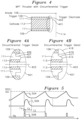
- FIG. 4 shows a section view of an insulator for a circumferential trigger thruster.
- FIGS. 4 A and 4 B shows detail views of FIG. 4 .
- FIG. 5 shows overview waveform plots for the operation of the plasma thruster.
- FIG. 6 shows a plot for anode current and anode voltage over a thrust cycle.
- FIG. 7 shows a plot for operation of the plasma thruster from a trigger cycle to a thrust cycle.
- FIG. 8 shows a plot for trigger cycle waveforms.
- FIG. 9 shows a waveform plot for a missed trigger.
- FIG. 10 shows a perspective view of a three axis thrust cube.
- FIG. 11 shows a schematic drawing of a thrust power supply coupled to a trigger driver for driving the three axis thrust cube of FIG. 10 .
- FIG. 1 A shows a front view of a first configuration for a metal plasma thruster (MPT) where a central trigger electrode 110 is separated from a cathode face 108 by an annular insulator 101 over which an initiation plasma is formed.
- the insulator may be formed from glass, Alumina (aluminum oxide), or any ceramic with a high melting point.
- FIG. 1 B shows an alternative circumferential trigger configuration where a central cathode face 113 is separated by an outer circumferential trigger electrode 109 with insulator 111 positioned inside the radial extent of the trigger electrode 109 .
- Axial trigger configuration FIG. 1 A is a front view best understood in combination with side section view FIG. 3
- circumferential trigger configuration FIG. 1 B is best understood in combination with side section view FIG. 4 .
- the cathode 108 of FIG. 1 A or 113 of FIG. 1 B may be formed of any material, preferably a metal which provides a comparatively high erosion rate during operation, indicating a comparatively high mass flow rate, in combination with a high exhaust speed.
- Suitable materials include any of the elements: Lithium (Li), Carbon (C), Magnesium (Mg), Aluminum (Al), Titanium (Ti), Chromium (Cr), Niobium (Nb), Molybdenum (Mo), Tantalum (Ta), Tungsten (W), Platinum (Pt), or Uranium (U).
- AMU atomic mass unit
- I SP change in momentum per unit of propellant consumed
- the propellants listed in Table 1 are not exclusive, as any conducting solid element or alloy may be used as an electrode material in the MPT, ranging from Lithium at the low mass end to depleted Uranium or higher at the upper mass end.
- a comprehensive list of suitable cathode metals for the present invention, sorted by melting point, includes: Magnesium, Aluminum, Radium, Barium, Strontium, Cerium, Europium, Ytterbium, Calcium, Lanthanum, Praseodymium, Silver, Neodymium, Actinium, Gold, Samarium, Copper, Promethium, Uranium, Manganese, Beryllium, Gadolinium, Terbium, Dysprosium, Nickel, Holmium, Cobalt, Erbium, Yttrium, Iron, Scandium, Thulium, Palladium, Protactinium, Lutetium, Titanium, Thorium, Platinum, Zirconium, Chromium, Vanadium, Rhodium, Hafnium,
- Alternative metals with a lower melting point which could be used as a cathode in the present MPT include: Francium, Cesium, Gallium, Rubidium, Potassium, Sodium, Indium, Lithium, Tin, Polonium, Bismuth, Thallium, Cadmium, Lead, and Zinc. These materials may be referred to as “tier 2” metals, which may be present in elemental form, or as alloys of other metals. In the scope of the present invention, the above “tier 1” and “tier 2” metals listed above are understood to suitable for use as cathode material for the MPT individually, or alloyed with other metals, for use in forming the MPT cathode in the present invention. Although the metals are sorted by melting point, this is not intended to imply a preferred order for use in the cathode of the MPT.
- the MPT offers a broad range of ISP from 800 s to 2400 s, whereas PTFE (Teflon®) of the prior art PPT is limited to a narrower range of values of roughly 525 s to 600 s.
- the anode 114 is a conductive electrode positioned a separation distance from the cathode ( 108 or 113 ) face, and the anode 114 has greater than 80% porosity to allow passage of accelerated metal ions.
- the anode 114 may have any shape including a screen or an annular ring or a torus with a diameter which is equal to or greater than the diameter of the cathode 108 of FIG. 1 A or trigger electrode 109 of FIG. 1 B .
- the anode may be formed from any conductive material, refractory metal, or a stainless steel alloy such as an alloy containing at least steel and chromium, and with the largest practical porosity, so that the metal ions are accelerated from the cathode, but propagate through the porous anode.
- FIG. 1 A- 1 shows a section view of an MPT where the trigger electrode 110 generates a pulsatile voltage which is applied between the trigger electrode 110 and cathode 108 and which exceeds a breakdown voltage across the insulator 101 .
- the high voltage pulse is applied between the trigger lead 102 and the grounded cathode lead 104 using the power supply 201 of FIG. 2 .
- FIG. 2 shows a power supply 201 for use with any of the plasma thruster configurations previously described.
- a power supply 202 charges an energy storage capacitor C 1 206 .
- a controller 203 determines the rate of charge, how often to discharge thrust, when to close switch 208 , and for how long to close switch 208 according to requested thrust, material consumption, trigger requirements, and other input parameters.
- Switch 208 is normally off, and may be an insulated gate bipolar transistor (IGBT), a field effect transistor (FET), bipolar transistor, or any other controllable switch element capable of withstanding high voltages (in excess of 1 kV) and 100 A currents, the switch 208 having low switch on resistance ( ⁇ 30 m ⁇ ), and a fast ( ⁇ 500 ns) switching time.
- IGBT insulated gate bipolar transistor
- FET field effect transistor
- trigger 102 and grounded cathode 104 are equipotential to each other.
- a trigger voltage Vg is delivered as a short pulse of duration T 1 (of FIG. 5 ) to switch 208 , which closes and causes a current to flow through L 1 for a duration of time T 1 sufficient to generate an initiation plasma when switch 208 is opened at the end of T 1 , which causes a positive voltage spike to be developed at switch 208 , which is coupled through trigger capacitor C 2 210 to trigger lead 102 .
- the resulting trigger plasma formed between the trigger electrode 110 / 109 of FIGS.
- the interval T 1 for which the gate Vg enables the switch 208 is selected to be sufficient only for plasma initiation, after which the plasma thrust interval T 2 (of FIG. 5 ) begins, during which time the main plasma from cathode 108 / 113 (associated with cathode lead 104 ) to anode 114 (associated with anode lead 106 ) develops, through the circuit C 1 206 , L 1 204 , anode lead 106 and cathode lead 104 .
- inductor L 1 204 and the interval T 1 are selected to be the smallest possible values sufficient to generate a sufficiently high voltage (LdI/dt) to trigger micro-discharge plasmas across the face of the metallized insulator (region 301 of FIG. 3 or region 401 of FIG. 4 with surface profile 402 and central axis 403 ) and thereby to facilitate arc breakdown between the cathode 104 and anode 106 .
- the first capacitor C 1 206 is charged (generally up to 100 V or other suitable voltage) by a DC current directly from power supply 202 , such as from a spacecraft solar source, or with a charge rate regulated by controller 203 .
- a DC current directly from power supply 202 , such as from a spacecraft solar source, or with a charge rate regulated by controller 203 .
- both the switch (IGBT or MOSFET 208 ) and the trigger plasma path from trigger electrode 110 to cathode 108 across insulator 101 (of FIG. 1 ), or trigger electrode 109 to cathode 113 across insulator 111 are open and the vacuum gap between the cathode ( 108 or 113 , respectively) and anode 114 also ensures that no current flows back to the power supply ground across that gap.
- a trigger signal Vg is sent by controller 203 to the control input of the switch to close the switch 208 and current flows from C 1 206 through the coil L 1 204 , the switch 208 and returns to the capacitor ground, building increasing current in L 1 204 until such current allows generation of a sufficiently high LdI/dt voltage when the switch T 1 208 is opened, to generate a trigger electrode arc.
- the switch 208 is opened by control input Vg returning to 0 V, and the voltage (LdI/dt) developed by L 1 204 is delivered through C 2 210 to the trigger electrode to initiate the plasma between the trigger electrode and cathode electrode across the insulator gap.
- Inductor 204 has an inductance value which is just high enough to generate an adequate breakdown voltage (such as in the range 200 V to 2000 V) across the insulator gap between cathode 108 / 113 and trigger electrode 110 / 109 .
- this inductor 204 may be small and low mass, as opposed to the inductor in the prior art VAT which must be of high enough value to store the required arc energy applied between anode and cathode of that configuration.
- the inductor is not the primary energy source for the arc and serves only to provide the LdI/dt voltage spike necessary to trigger the arc.
- the charge and energy to the arc are provided mainly by the storage capacitor C 1 .
- FIG. 5 shows waveforms of operation for the Metal Plasma Thruster.
- An energy storage capacitor (C 1 206 of FIG. 2 ) is charged by an external power source developing a voltage Vc 504 .
- Vc 504 When the capacitor voltage reaches a threshold voltage 502 and upon command from the controller 203 of FIG. 2 , the switch 208 is triggered by Vg 508 during T 1 , which causes the switch 208 to close.
- the trigger T 1 interval removes a small amount of charge from the capacitor, which is used to initiate a trigger plasma such as 120 shown in FIG. 1 A- 1 , or analogously across the insulator of region 301 of FIG. 3 or the insulator of region 401 of FIG. 4 .
- Subsequent to the trigger T 1 interval is the plasma thrust interval T 2 of FIG.
- FIG. 6 shows the current and voltage during the main cathode to anode arc period lasting an example thrust interval of 3 ms, corresponding to interval T 2 of FIG. 5 .
- Waveform 602 shows example anode electrode current
- waveform 604 shows example anode electrode voltage with respect to the grounded cathode, for an example fixed arc resistance of 70 m ⁇ and an arc sheath potential drop of 19 V.
- One component of applied voltage developing a plasma is the sheath potential plus an Ohmic voltage drop across the arc.
- the sheath potential is a well-known phenomenon in arc discharges, where ions from the main discharge plasma in the anode-cathode gap return across a cathode sheath, gaining energy, ⁇ 10 eV to 15 eV for each singly charged ion, and heat the cathode locally in several spots to support field enhanced thermionic emission of the electrons needed to carry the arc current from cathode to anode. Those current carrying electrons cross another thin sheath at the anode, gaining energy ( ⁇ 10 eV) and deposit that energy as heat into the anode.
- the sum of the cathode and anode sheath potentials is 19 V in this example.
- FIG. 7 shows the waveforms for an interval of time from 701 to 703 corresponding to the switch transitioning from T 1 (Vg on) to T 2 (Vg off), where the plot 704 shows capacitor C 1 charged, and the switch 208 closed until time 701 , during which first interval the current through C 1 206 , L 1 204 , and switch 208 ramps as In 702 until time 701 when the switch opens and the trigger plasma initiates.
- the current path transitions to C 1 , L 1 , C 210 and trigger electrode 102 , followed by the current flowing through anode 106 to cathode 104 .
- Plot I L1 702 shows a linear ramp up to about 70 A at time 701 during the first 90 ⁇ s of an example T 1 when the switch is closed, followed by a slight dip and a sinusoidal increase thereafter.
- FIG. 8 shows the waveforms for a segment in time which includes the trigger interval, shown starting at ⁇ 45 ⁇ s when the switch 208 opens at the end of T 1 interval 807 .
- the switch opens, its internal resistance rapidly increases, causing the current in the switch 208 to decay rapidly.
- the interruption of current through switch 208 causes the voltage applied to the trigger electrode Vtrig 806 to rapidly increase, causing a plasma to develop at the trigger electrode.
- trigger electrode current 804 begins to flow and generates more trigger plasma.
- the trigger plasma current path transitions from between cathode and trigger to between cathode and anode, and the trigger capacitor now drives current in the opposite direction and the trigger current 804 reverses polarity.
- the inductor current In 802 changes slope during the trigger plasma interval from 45 ⁇ s to 55 ⁇ s as the current starts to decay due to the rapidly increasing resistance in switch 208 .
- the change in current contributes to the LdI/dt voltage and as that voltage increases, current flowing through the switch 208 is diverted to the trigger electrode 102 for forming the initial trigger arc to the cathode.
- the switch is opened (at ⁇ 43 ⁇ s in the instant FIG. 8 example), the dip in current I L 802 in coil L 1 generates a voltage LdI/dt VTRIG 806 at the coil output node.
- the initial fast ( ⁇ 200 ns) voltage spike of 120 V passes through the blocking capacitor C 2 210 , which is selected to offer low impedance ( ⁇ 1 ⁇ ) to a fast ( ⁇ 1 ⁇ s) rise time pulse and creates a flashover plasma ( 120 of FIG. 1 A- 1 ) across the metallized ( ⁇ 10 ⁇ to 1 k ⁇ ) insulator surface (region 301 of FIG. 2 or region 401 of FIG. 4 ) between the trigger electrode ( 110 of FIG. 3 or 109 of FIG. 4 , respectively) and the cathode ( 108 of FIG. 3 or 113 of FIG. 4 , respectively).
- An example trigger current from the trigger electrode to cathode electrode has a magnitude of 45 A (which implies a flashover resistance of approximately 2.7 ⁇ ) and creates sufficient plasma 120 of FIG. 1 A- 1 to bridge the main cathode to anode gap and initiate a breakdown 122 of FIG. 1 A- 2 across the main cathode to anode gap.
- the arc breakdown is across a plasma bridge whose resistance is ⁇ 100 m ⁇ , allowing higher currents to flow from C 1 through L 1 and the arc discharge.
- the much higher resistance of the trigger path ensures that negligible current flows through the trigger electrode path, as shown by trigger current plot 804 which returns to zero at ⁇ 55 ⁇ s as the anode arc current increases.
- the blocking capacitor C 2 210 offers increasingly higher impedance as the current increases, going from ⁇ 1 ⁇ for the 100 ns rise-time of the switch voltage up to >6000 ⁇ during the slower period of the main arc.
- the trigger path is active only for on the order of 10 ⁇ s after the switch 208 is opened.
- the trigger electronic current 804 goes negative at 50 ⁇ s of FIG. 8 when the main plasma arc from cathode to anode ignites, since the blocking capacitor C 2 210 now drives current in the reverse direction through the arc.
- the switch 208 voltage drops to about 33 V after about 53 ⁇ s, which is the arc burning voltage (sheath drop+Ohmic drop across the arc resistance). In this example, the voltage reaches a peak of about 400 V before decaying back to the arc burning voltage of about 33 V.
- FIG. 9 shows the result when the trigger interval T 1 is too short, or not enough voltage is developed at the trigger electrode to initiate a plasma.
- the voltage developed by discontinuously interrupting the inductor current is LdI/dt, care must be taken not to exceed the breakdown voltage of switch 208 .
- This protection is provided by overvoltage device 209 , which may be any device which clamps a voltage which exceeds a threshold and has sufficiently fast response time to provide protection to the switch during transient voltage events.
- MOV metal oxide Varistor
- switch voltage 904 reaching 1200 V with weak or delayed plasma formation results in the MOV 209 shunting some of the current as shown in waveform 902 , thereby protecting the switch 208 from overvoltage breakdown.
- This protection device 209 clamp voltage is selected for prevention of overvoltage damage to switch 208 .
- Inductor current 906 is also shown for reference.
- the various charging times, plasma arc discharge times, cycle times, and circuitry are shown for example purposes only, and many other variations are possible.
- the plasma arc was described as being activated in discrete thrust events using discrete energy level stored in an inductor.
- a DC voltage source may be placed between anode electrode and cathode electrode, such that when the initiator electrode develops a plasma arc, the DC source maintains the plasma arc in steady state until the DC source is removed.
- the inductance of the inductance of the energy storage inductor and plasma electrode geometry and spacing governs the interval of time for which the arc is maintained, and the durations and waveforms given are illustrative in nature for the components used, and are not intended to limit the values of these components or waveform durations and times they produce.
- the shapes of insulator surfaces of region 301 of FIG. 3 , shown in detail FIG. 3 A , and region 401 of FIG. 4 , shown in detail FIG. 4 A are critical for the long-term operation of the plasma thruster.
- region 301 by stepping the insulator 101 to create a planar insulator surface 304 and proximal surfaces 305 and 306 below the cathode face 302 , the surface resistance of the depressed segment of the insulator 306 may be kept nearly constant over many plasma cycles and extend the longevity of the thruster.
- One specific function of the shape of the insulator 101 geometry is to provide one or more surfaces of the insulator which are obscured from re-deposition of metal ejected from the cathode 108 / 113 .
- Example proximal surfaces 305 or 306 of FIG. 3 A may perform this function.
- the surface of the insulator 101 may rely on an initial metallization on the order of 1 ⁇ thickness with micro-gaps to form areas where micro-arcs may form in the small gaps of the surface metallization, which are critical to the initiation of the plasma arc.
- FIG. 3 B An insulator surface resistance in the range of tens of ohms to thousands of ohms is preferred, although other resistances may be used which form microplasmas in the gaps between surface metallization.
- Other insulator surface profiles are shown in the insulator detail FIG. 3 B , showing a ramp with obscured surface 314 adjacent to a deposition surface 312 , FIG. 3 C showing a sawtooth with obscured surface 320 and exposed surface 318 , or alternative of FIG. 3 C- 1 which shows a sawtooth with peaks 321 providing a gradient of material removal/deposition between the two surfaces (one fully obscured and one partially obscured) on either side of peak 321 .
- FIG. 3 B shows a ramp with obscured surface 314 adjacent to a deposition surface 312
- FIG. 3 C showing a sawtooth with obscured surface 320 and exposed surface 318
- FIG. 3 C- 1 which shows a sawtooth with peaks 321 providing a gradient of material removal/de
- FIG. 3 D shows a ramped insulator 326 , which may be used with a trigger electrode 110 which has a surface 330 flush with depressed region of insulator 101 , or the trigger electrode 110 may extend to full height flush to the cathode 108 as shown with profile 328 . Additionally, the trigger electrode profile may be flat, as shown, or tapered to a point (not shown), beveled to a flat surface 328 (not shown), or rounded (not shown).
- FIGS. 3 E, 3 F , and 3 G show additional embodiments of insulator 101 , with surfaces 318 , 324 , 328 / 330 , respectively, which are obscured from redeposition of plasma ejected from the cathode by geometry with respect to returning plasma metal ions.
- Insulator 101 may have any shape which provides at least one surface obscured from redeposition, or in equilibrium for erosion from plasma trigger events, and re-deposition from returning metal ions after the trigger events. Insulator 101 may have other non-planar surface features such as rippled surface features which provide an equilibrium of metal deposition and removal from each plasma event, or a roughened surface which preserves microplasma formation in the microgaps on the metallization.
- the design constraint for the insulator may be stated thus: the thickness of new material deposited on each pulse over obscured surfaces such as 305 and 306 of FIG. 3 A (or the obscured surfaces of the other exemplar insulators of FIGS. 3 B- 3 G ), in total, should be equal to the thickness that is eroded by each trigger flashover event.
- the depth of 306 relative to surface 304 and width of the groove forming surfaces 305 and 306 is selected to have an aspect ratio of 2 or more, and the equilibrium of deposition/erosion is applied to at least one of surface 305 or 306 .
- the aspect ratio of the features is understood to be the depth of the feature parallel to the cathode central axis divided by the width of the feature parallel to the face of the cathode.
- the total propellant mass burned in this period is approximately 30 g.
- a single Mo cathode in the MPT 30 mm in diameter would erode this mass over a depth of 4 mm.
- Insulator 301 is shown in detail FIG. 3 A .
- metal ions from cathode 108 tend to accumulate on insulating interface 304 . This accumulation may reduce the surface resistance for the trigger current.
- a groove 306 obscures proximal regions of the insulator from metal ion re-deposition. The depth of groove is selected such that the material which is removed by a plasma ignition event is equal to the re-deposition of new material from a main plasma arc event.
- FIG. 4 A shows a similar groove formed by surfaces 406 and 406 which are shielded from re-deposition of ions released from cathode 113 , whereas surface 404 is expected to receive depositions more heavily than surfaces 406 or 407 .
- the insulator configurations for an axial trigger electrode of FIG. 3 may be utilized in the circumferential trigger geometry of FIG. 4 by mirroring the insulator feature so that a surface profile which was near a central trigger electrode is maintained when the trigger electrode is circumferential. For example, the insulator profile of FIG.
- the insulator 101 features 414 , 417 , and 416 of circumferential trigger FIG. 4 B may be transformed from the corresponding insulator 101 features 312 , 314 , and 316 , respectively, of axial trigger FIG. 3 B by mirroring the surface features.
- the other insulator profiles shown in the figure sequence 3 C to 3 G may be similarly transformed for circumferential trigger use, thereby maintaining at least one proximal surface which is obscured from re-deposition of plasma ions ejected from the cathode.
- the insulator 101 / 111 material need not be a high temperature ceramic, as the insulator surface is exposed to a small fraction of the trigger plasma briefly during part of T 1 , and T 1 is a small fraction of the plasma duration T 1 +T 2 .
- a suitable insulator 101 / 111 is one which supports on the order of 1 ⁇ of surface metal deposition and has a melting temperature sufficient to withstand the energy imparted from the trigger arc over repeated cycles.
- the MPT has a diameter in the range of 5 mm to 40 mm.
- the MPTs are arranged over one or more surfaces of a cube of approximate dimension 10 cm ⁇ 10 cm ⁇ 10 cm, one or more surfaces of the cube having a plurality of MPTs, each MPT including an anode lead 106 which includes a capacitor C 2 210 to the respective MPT trigger, and the cathode leads 104 commonly connected.
- a single power supply 201 may be used for a cube face to control a particular orthogonal thrust direction, each MPT (or a group of MPTs) on a particular surface connected via a switch element (reed relay or other low resistance switch), with one group of MPTs at a time connected, and the others isolated.
- a switch element relay or other low resistance switch
- one or more MPTs may be selected until its useful lifetime of thrust pulses is exhausted, after which the MPT with associated capacitor 210 may be isolated, and a new MPT and associated capacitor 210 selected for continued operation.
- FIG. 10 shows an example 3 axis thrust control cube, where five of the six external surfaces have thrusters attached to provide orthogonal thrust directions.
- each surface of the thrust cube 1000 has four thrusters mounted in an orthogonal arrangement, with bottom thrusters 1006 providing +Z thrust, top thrusters 1002 providing ⁇ Z thrust, left side thrusters 1004 providing +X thrust, and right side thrusters 1010 providing ⁇ X thrust.
- Front thrusters 1010 provide +Y thrust.
- each opposite surface of the satellite would have a thrust cube, which would have a surface configured to provide an opposing ⁇ Y thrust.
- 2 to 8 or more such thrusters of FIG. 10 may be employed.
- Each surface may have an arbitrary number of thrusters, which may be activated individually or in groups to provide granularity of thrust events with orthogonal direction.
- FIG. 11 shows a schematic diagram of an example three axis thruster for use with the thrust cube of FIG. 10 .
- Power supply 1101 is operative as was described in FIG. 2 , where a DC supply 1102 charges energy storage capacitor 1108 C 1 , as before.
- Capacitor C 1 may be two 21 mF capacitors in parallel.
- trigger switch 1110 closes for a duration of time sufficient to maximize an instantaneous current in L 1 1106 , after which switch 1110 releases, allowing the current stored in inductor L 1 1106 to be directed to one or more selected thrusters in thruster cube assembly 1118 .
- Trigger switch 1110 may be formed using four IGBT devices, and storage inductor L 1 1106 can be a 70 uH inductor, thereby providing 150 A rising roughly linearly in 320 us.
- Blocking capacitor 1130 can be a value such as 500 nF which couples the trigger voltage to a selected trigger electrode through a trigger switch such as insulated gate bipolar transistor (IGBT) 1126 .
- the selection of individual thrusters is accomplished using thruster select inputs 1132 , which are coupled to isolating drivers 1128 , which may be optoisolators or other isolating switch elements which allow for low voltage control and isolation from the large magnitude transient voltages of the actuated thrusters of 1118 .
- Each driver such as 1128 is coupled to a trigger switch 1126 which may be an IGBT 1126 , which is either in an ON state or OFF state.
- a trigger switch 1126 which may be an IGBT 1126 , which is either in an ON state or OFF state.
- the instantaneous current is coupled through blocking capacitor 1130 and applied to the collector (drain) electrode of the trigger switches such as 1134 , which in the ON state is coupled to the emitter (source) 1136 , which couples the associated trigger current to the trigger electrode of thruster 1124 , which initiates a triggering plasma from the cathode to the trigger electrode, which plasma initiates the main arc discharge from the cathode electrode of 1124 to anode electrode 1120 , generating thrust as was previously described.
- Each driver of the trigger driver 1116 is configured so that each individual thruster 1138 through 1122 are individually selectable for a thrust generation event.
- the duration of the plasma provided by the circuit of FIG. 11 is primarily governed by the energy storage device 1106 and thruster electrode geometry, and may within the range of orders of magnitude greater than 6 us or orders of magnitude less than 6 us.
- a switchable DC source may be applied across the anode 1112 and cathode 1114 electrodes of FIG. 11 , and selected thrusters initiated with a voltage pulse to the initiator electrode (replacing capacitor 1130 ) sufficient to initiate the plasma in selected thrusters, where the plasma is continuously operative until the switchable DC source is removed.
- the individual thruster geometry used in the thruster cube 1118 is shown as the circumferential trigger geometry for thrusters 1138 through 1122 of FIG. 11 , including any of the configurations shown in FIG. 1 B, 4 , 4 A , or 4 B.
- Example circumferential trigger thruster 1138 is shown with outer trigger electrode 1142 , inner cathode electrode 1142 , and insulator 1146 .
- Thrusters 1138 through 1122 can alternatively be any of the axial geometries previously described for FIG. 1 A, 3 , 3 A, 3 B, 3 C, 3 D, 3 E, 3 F , or 3 D.
- thrusters 1138 to 1122 of thruster cube 1118 may be placed on a single surface or multiple surfaces of the cube of FIG. 10 with any number of thrusters on a particular surface.
- each of the thrusters on a surface of the thruster cube are configured to be connected to the anode 1112 and cathode 1114 conductors of the power supply 1101 and each thruster is individually selectable using thruster input 1132 which selects the particular thrusters to receive a trigger pulse to produce thrust, whereas the non-selected thrusters which do not receive the trigger pulse remain passive. In this manner, granularity of pulsed plasma from one or more orthogonal surfaces is possible.
- the pulsed power supply 1101 and trigger driver 1116 are packaged in an inner enclosure of FIG. 10 which has thrusters of 1118 on outer surfaces as shown in FIG. 10 , thereby providing low loss coupling from inductor 1106 to selected thrusters of thruster cube 1118 .
- the MPT differs from the prior art VAT in three distinct ways:
- the propellant mass M p is related to the initial spacecraft mass M o by:
- the propellant mass M p required by each of these engines is calculated from Eq. 1 and given in the last row of the table.
- the thrust efficiency of any of the electric propulsion systems is determined primarily by the energy cost to create the ion from the solid (Teflon® PPT or MPT) or liquid (FEEP) state.
- the FEEP is the most efficient of all three systems since the field evaporation is a direct, non-thermal extraction by quantum tunneling across a potential barrier.
- the Teflon® PPT and the MPT both use a thermal process to ionize the atoms. In such a thermal process the ionization cost is much higher, approximately 100 eV per atom vs. approximately 10 eV per atom in the FEEP.
- thrust/power input ratio of the FEEP is higher than that of the Teflon® PPT or the MPT. But the mass of the MPT (for a given power) is much lower than that of the FEEP. Hence the thrust/mass ratio of the MPT and FEEP are comparable.
- the examples shown in the present invention are intended for understanding the invention, which may be practiced many different ways. It is understood that the example values for the inductor, first capacitor, second capacitor, voltages and currents, trigger electrode to cathode electrode, insulator gap and insulator surface profile and shape are typical examples, rather than limitations of the invention, which is established by the claims which follow. Quantities which are referenced within an order of magnitude are understood to be a factor of 10, or more, larger or smaller than the referenced quantity. In an example variation, the trigger current is periodically measured and used to change the threshold voltage for starting the thrust cycle adaptively to higher or lower voltage levels.
- the detection of additional metal deposition on the surface of the insulator would result in a change in threshold voltage to increase the erosion rate
- the detection of increased metal erosion would result in a change in threshold voltage in the opposite direction.
- the direction of controller threshold adjustment to higher or lower voltages may be performed adaptively based on measurement, or based on an electrode wear, pulse discharge count, or other algorithm.
Landscapes
- Engineering & Computer Science (AREA)
- Physics & Mathematics (AREA)
- Chemical & Material Sciences (AREA)
- Combustion & Propulsion (AREA)
- Plasma & Fusion (AREA)
- Remote Sensing (AREA)
- Aviation & Aerospace Engineering (AREA)
- Mechanical Engineering (AREA)
- General Engineering & Computer Science (AREA)
- Spectroscopy & Molecular Physics (AREA)
- Astronomy & Astrophysics (AREA)
- General Physics & Mathematics (AREA)
- Plasma Technology (AREA)
Abstract
Description
| TABLE 1 | |||||
| 1 | 2 | 3 | 4 | ||
| Metal | AMU | speed, m/s | ISP (s) | ||
| C | 12 | 17403 | 1774 | ||
| Mg | 24.31 | 19637 | 2002 | ||
| Al | 26.98 | 23500* | 2396 | ||
| Ti | 47.87 | 15354 | 1565 | ||
| Cr | 52.00 | 16161 | 1647 | ||
| Nb | 92.91 | 16855 | 1718 | ||
| Mo | 95.94 | 17235 | 1757 | ||
| Ta | 180.95 | 11990 | 1222 | ||
| W | 183.84 | 11033 | 1125 | ||
| Pt | 195.08 | 8105 | 826 | ||
| U | 238.03 | 11339 | 1156 | ||
-
- (1) the MPT has plasma arc currents in the range of ˜200 A to 300 A or more vs. the VAT which has currents of ˜100 A, which reflect the characteristic of the underlying energy storage elements: inductors (with higher Ohmic loss) result in lower currents than capacitors (with lower Ohmic loss).
- (2) The MPT arc has a longer duration (˜3 ms to 12 ms) compared to the arc duration in a VAT (˜100 μs to 500 μs), due to the use of capacitors as storage elements.
- (3) The inductor in an MPT for initiating the plasma is on the order of 40 μH-80 μH vs. 1 mH for a VAT which stores the plasma energy in the inductor. The inductor in the MPT stores<2% of the energy delivered to the arc on each cycle.
| RAISE A 5 kg nano-SAT FROM 500-700 KM ORBIT |
| Mo MPT | Busek PPT | ACCION ESP | ||||
| speed | 17235 | 5258 | 17658 | m/ | ||
| ΔV | ||||||
| 110 | 110 | 110 | m/s | |||
| Mo | 5 | 5 | 5 | kg | ||
| Mp | 32 | 104 | 31 | g | ||
Claims (21)
Priority Applications (1)
| Application Number | Priority Date | Filing Date | Title |
|---|---|---|---|
| US17/214,893 US11644016B2 (en) | 2018-05-23 | 2021-03-28 | Metal plasma thruster cube |
Applications Claiming Priority (2)
| Application Number | Priority Date | Filing Date | Title |
|---|---|---|---|
| US15/987,885 US10989179B1 (en) | 2018-05-23 | 2018-05-23 | Metal plasma thruster cube |
| US17/214,893 US11644016B2 (en) | 2018-05-23 | 2021-03-28 | Metal plasma thruster cube |
Related Parent Applications (1)
| Application Number | Title | Priority Date | Filing Date |
|---|---|---|---|
| US15/987,885 Continuation US10989179B1 (en) | 2018-05-23 | 2018-05-23 | Metal plasma thruster cube |
Publications (2)
| Publication Number | Publication Date |
|---|---|
| US20210301798A1 US20210301798A1 (en) | 2021-09-30 |
| US11644016B2 true US11644016B2 (en) | 2023-05-09 |
Family
ID=75587436
Family Applications (2)
| Application Number | Title | Priority Date | Filing Date |
|---|---|---|---|
| US15/987,885 Active 2039-08-29 US10989179B1 (en) | 2018-05-23 | 2018-05-23 | Metal plasma thruster cube |
| US17/214,893 Active 2038-09-30 US11644016B2 (en) | 2018-05-23 | 2021-03-28 | Metal plasma thruster cube |
Family Applications Before (1)
| Application Number | Title | Priority Date | Filing Date |
|---|---|---|---|
| US15/987,885 Active 2039-08-29 US10989179B1 (en) | 2018-05-23 | 2018-05-23 | Metal plasma thruster cube |
Country Status (1)
| Country | Link |
|---|---|
| US (2) | US10989179B1 (en) |
Families Citing this family (7)
| Publication number | Priority date | Publication date | Assignee | Title |
|---|---|---|---|---|
| US10989179B1 (en) * | 2018-05-23 | 2021-04-27 | Mahadevan Krishnan | Metal plasma thruster cube |
| CN111348224B (en) * | 2020-04-16 | 2022-05-24 | 哈尔滨工业大学 | Micro-cathode arc propulsion system |
| WO2023025846A1 (en) * | 2021-08-24 | 2023-03-02 | Porkchop Ab | Power conversion system for electrical powered thrusters |
| CN115247632B (en) * | 2022-05-13 | 2024-07-26 | 中国人民解放军国防科技大学 | Array type electric control solid electric arc micro-thruster |
| WO2024118039A2 (en) * | 2022-10-17 | 2024-06-06 | Benchmark Space Systems, Inc. | Satellite metal plasma thruster and control circuit |
| CN118757360A (en) * | 2024-07-16 | 2024-10-11 | 哈尔滨工业大学 | A micro cathode arc thruster |
| CN119712475A (en) * | 2024-12-23 | 2025-03-28 | 北京理工大学 | Pulse plasma thruster based on tooth-shaped propellant |
Citations (1)
| Publication number | Priority date | Publication date | Assignee | Title |
|---|---|---|---|---|
| US10989179B1 (en) * | 2018-05-23 | 2021-04-27 | Mahadevan Krishnan | Metal plasma thruster cube |
Family Cites Families (3)
| Publication number | Priority date | Publication date | Assignee | Title |
|---|---|---|---|---|
| US4785220A (en) * | 1985-01-30 | 1988-11-15 | Brown Ian G | Multi-cathode metal vapor arc ion source |
| US6465780B1 (en) * | 1999-03-31 | 2002-10-15 | The Regents Of The University Of California | Filters for cathodic arc plasmas |
| CA2998508C (en) * | 2015-09-15 | 2023-09-26 | Neumann Space Pty Ltd | Internal wire-triggered pulsed cathodic arc propulsion system |
-
2018
- 2018-05-23 US US15/987,885 patent/US10989179B1/en active Active
-
2021
- 2021-03-28 US US17/214,893 patent/US11644016B2/en active Active
Patent Citations (1)
| Publication number | Priority date | Publication date | Assignee | Title |
|---|---|---|---|---|
| US10989179B1 (en) * | 2018-05-23 | 2021-04-27 | Mahadevan Krishnan | Metal plasma thruster cube |
Non-Patent Citations (1)
| Title |
|---|
| Brown "Vacuum Arc Ion Sources: A review" (Year: 2012). * |
Also Published As
| Publication number | Publication date |
|---|---|
| US20210301798A1 (en) | 2021-09-30 |
| US10989179B1 (en) | 2021-04-27 |
Similar Documents
| Publication | Publication Date | Title |
|---|---|---|
| US11644016B2 (en) | Metal plasma thruster cube | |
| Gilmour et al. | Pulsed metallic-plasma generators | |
| US4594630A (en) | Emission controlled current limiter for use in electric power transmission and distribution | |
| Schein et al. | Inductive energy storage driven vacuum arc thruster | |
| RU2748625C2 (en) | Pulsed cathodic arc propulsion system with internal wire initiator | |
| US6373023B1 (en) | ARC discharge initiation for a pulsed plasma thruster | |
| US11077962B2 (en) | High thrust to power micro cathode arc thruster | |
| WO2013122633A1 (en) | Arc devices and moving arc couples | |
| US6818853B1 (en) | Vacuum arc plasma thrusters with inductive energy storage driver | |
| US20110258981A1 (en) | Micro-cathode thruster and a method of increasing thrust output for a micro-cathode thruster | |
| US12209577B2 (en) | Fiber-fed advanced pulsed plasma thruster (FPPT) | |
| US20070045248A1 (en) | Vacuum arc plasma thrusters with inductive energy storage driver | |
| US11480162B1 (en) | Satellite metal plasma thruster and control circuit | |
| JP7804151B2 (en) | Metallic plasma thruster and control circuit for satellites | |
| US11242844B2 (en) | Fiber-fed advanced pulsed plasma thruster (FPPT) | |
| Schein et al. | Low mass vacuum arc thruster system for station keeping missions | |
| US10570892B2 (en) | Fiber-fed advanced pulsed plasma thruster (FPPT) | |
| KR20220059500A (en) | Electrically Conductive Liquid Propellant Pulsed Plasma Thruster | |
| Flynn | The discharge mechanism in the high-vacuum cold-cathode pulsed X-ray tube | |
| Neumann et al. | A pulsed cathodic arc spacecraft propulsion system | |
| US20190373711A1 (en) | System for generating a plasma jet of metal ions | |
| Philip et al. | Recent hollow cathode investigations at the Royal Aircraft Establishment | |
| Fearn | The ultimate performance of gridded ion thrusters for interstellar missions | |
| Schein et al. | Discharges in space: plasmas for satellite propulsion | |
| Nakata et al. | Performance of ThO2-W, Y2O3-W and La2O3-W cathodes in quasi-steady magnetoplasmadynamic thrusters |
Legal Events
| Date | Code | Title | Description |
|---|---|---|---|
| FEPP | Fee payment procedure |
Free format text: ENTITY STATUS SET TO UNDISCOUNTED (ORIGINAL EVENT CODE: BIG.); ENTITY STATUS OF PATENT OWNER: SMALL ENTITY |
|
| FEPP | Fee payment procedure |
Free format text: ENTITY STATUS SET TO SMALL (ORIGINAL EVENT CODE: SMAL); ENTITY STATUS OF PATENT OWNER: SMALL ENTITY |
|
| AS | Assignment |
Owner name: KRISHNAN, MAHADEVAN, CALIFORNIA Free format text: ASSIGNMENT OF ASSIGNORS INTEREST;ASSIGNOR:VELAS, KATHLEEN M.;REEL/FRAME:056859/0141 Effective date: 20190115 |
|
| STPP | Information on status: patent application and granting procedure in general |
Free format text: DOCKETED NEW CASE - READY FOR EXAMINATION |
|
| AS | Assignment |
Owner name: ALAMEDA APPLIED SCIENCES CORPORATION, CALIFORNIA Free format text: ASSIGNMENT OF ASSIGNORS INTEREST;ASSIGNOR:KRISHNAN, MAHADEVAN;REEL/FRAME:060678/0621 Effective date: 20220601 |
|
| STPP | Information on status: patent application and granting procedure in general |
Free format text: NON FINAL ACTION MAILED |
|
| AS | Assignment |
Owner name: BENCHMARK SPACE SYSTEMS, INC., VERMONT Free format text: ASSIGNMENT OF ASSIGNORS INTEREST;ASSIGNOR:ALAMEDA APPLIED SCIENCES CORPORATION;REEL/FRAME:061742/0552 Effective date: 20221003 |
|
| STCF | Information on status: patent grant |
Free format text: PATENTED CASE |
|
| AS | Assignment |
Owner name: ALAMEDA APPLIED SCIENCES CORPORATION, CALIFORNIA Free format text: SECURITY INTEREST;ASSIGNOR:BENCHMARK SPACE SYSTEMS, INC.;REEL/FRAME:066981/0563 Effective date: 20240401 |
|
| AS | Assignment |
Owner name: ALAMEDA APPLIED SCIENCES CORPORATION, CALIFORNIA Free format text: ASSIGNMENT OF ASSIGNORS INTEREST;ASSIGNOR:BENCHMARK SPACE SYSTEMS, INC.;REEL/FRAME:069286/0715 Effective date: 20241114 |