US11632704B2 - Techniques for integrated access and backhaul topology discovery - Google Patents
Techniques for integrated access and backhaul topology discovery Download PDFInfo
- Publication number
- US11632704B2 US11632704B2 US17/028,526 US202017028526A US11632704B2 US 11632704 B2 US11632704 B2 US 11632704B2 US 202017028526 A US202017028526 A US 202017028526A US 11632704 B2 US11632704 B2 US 11632704B2
- Authority
- US
- United States
- Prior art keywords
- node
- message
- network node
- token
- aspects
- Prior art date
- Legal status (The legal status is an assumption and is not a legal conclusion. Google has not performed a legal analysis and makes no representation as to the accuracy of the status listed.)
- Active
Links
- 238000000034 method Methods 0.000 title claims description 132
- 238000004891 communication Methods 0.000 claims abstract description 51
- 230000015654 memory Effects 0.000 claims description 28
- 230000011664 signaling Effects 0.000 claims description 25
- 238000013507 mapping Methods 0.000 claims description 16
- 230000006978 adaptation Effects 0.000 claims description 9
- 230000008569 process Effects 0.000 description 60
- 230000006870 function Effects 0.000 description 33
- 230000005540 biological transmission Effects 0.000 description 26
- 238000010586 diagram Methods 0.000 description 17
- 238000005516 engineering process Methods 0.000 description 12
- 238000012545 processing Methods 0.000 description 3
- 230000001413 cellular effect Effects 0.000 description 2
- 230000001419 dependent effect Effects 0.000 description 2
- 238000013461 design Methods 0.000 description 2
- 239000000835 fiber Substances 0.000 description 2
- 241000700159 Rattus Species 0.000 description 1
- 230000002776 aggregation Effects 0.000 description 1
- 238000004220 aggregation Methods 0.000 description 1
- 230000006399 behavior Effects 0.000 description 1
- 238000004590 computer program Methods 0.000 description 1
- 238000010276 construction Methods 0.000 description 1
- 125000004122 cyclic group Chemical group 0.000 description 1
- 238000001514 detection method Methods 0.000 description 1
- 230000009977 dual effect Effects 0.000 description 1
- 230000007774 longterm Effects 0.000 description 1
- 238000004519 manufacturing process Methods 0.000 description 1
- 238000012986 modification Methods 0.000 description 1
- 230000004048 modification Effects 0.000 description 1
- 230000008520 organization Effects 0.000 description 1
- 230000002441 reversible effect Effects 0.000 description 1
- 239000004984 smart glass Substances 0.000 description 1
- 238000000638 solvent extraction Methods 0.000 description 1
- 230000003595 spectral effect Effects 0.000 description 1
- 238000001228 spectrum Methods 0.000 description 1
- 230000001360 synchronised effect Effects 0.000 description 1
- 238000011144 upstream manufacturing Methods 0.000 description 1
- 210000000707 wrist Anatomy 0.000 description 1
Images


Classifications
-
- H—ELECTRICITY
- H04—ELECTRIC COMMUNICATION TECHNIQUE
- H04W—WIRELESS COMMUNICATION NETWORKS
- H04W40/00—Communication routing or communication path finding
- H04W40/24—Connectivity information management, e.g. connectivity discovery or connectivity update
- H04W40/246—Connectivity information discovery
-
- H—ELECTRICITY
- H04—ELECTRIC COMMUNICATION TECHNIQUE
- H04W—WIRELESS COMMUNICATION NETWORKS
- H04W24/00—Supervisory, monitoring or testing arrangements
- H04W24/02—Arrangements for optimising operational condition
-
- H—ELECTRICITY
- H04—ELECTRIC COMMUNICATION TECHNIQUE
- H04W—WIRELESS COMMUNICATION NETWORKS
- H04W40/00—Communication routing or communication path finding
- H04W40/02—Communication route or path selection, e.g. power-based or shortest path routing
- H04W40/22—Communication route or path selection, e.g. power-based or shortest path routing using selective relaying for reaching a BTS [Base Transceiver Station] or an access point
-
- H—ELECTRICITY
- H04—ELECTRIC COMMUNICATION TECHNIQUE
- H04W—WIRELESS COMMUNICATION NETWORKS
- H04W68/00—User notification, e.g. alerting and paging, for incoming communication, change of service or the like
- H04W68/005—Transmission of information for alerting of incoming communication
-
- H—ELECTRICITY
- H04—ELECTRIC COMMUNICATION TECHNIQUE
- H04W—WIRELESS COMMUNICATION NETWORKS
- H04W76/00—Connection management
- H04W76/10—Connection setup
- H04W76/11—Allocation or use of connection identifiers
-
- H—ELECTRICITY
- H04—ELECTRIC COMMUNICATION TECHNIQUE
- H04W—WIRELESS COMMUNICATION NETWORKS
- H04W88/00—Devices specially adapted for wireless communication networks, e.g. terminals, base stations or access point devices
- H04W88/08—Access point devices
- H04W88/085—Access point devices with remote components
-
- H—ELECTRICITY
- H04—ELECTRIC COMMUNICATION TECHNIQUE
- H04W—WIRELESS COMMUNICATION NETWORKS
- H04W88/00—Devices specially adapted for wireless communication networks, e.g. terminals, base stations or access point devices
- H04W88/14—Backbone network devices
-
- H—ELECTRICITY
- H04—ELECTRIC COMMUNICATION TECHNIQUE
- H04W—WIRELESS COMMUNICATION NETWORKS
- H04W92/00—Interfaces specially adapted for wireless communication networks
- H04W92/04—Interfaces between hierarchically different network devices
- H04W92/12—Interfaces between hierarchically different network devices between access points and access point controllers
-
- H—ELECTRICITY
- H04—ELECTRIC COMMUNICATION TECHNIQUE
- H04W—WIRELESS COMMUNICATION NETWORKS
- H04W92/00—Interfaces specially adapted for wireless communication networks
- H04W92/16—Interfaces between hierarchically similar devices
- H04W92/20—Interfaces between hierarchically similar devices between access points
-
- H—ELECTRICITY
- H04—ELECTRIC COMMUNICATION TECHNIQUE
- H04W—WIRELESS COMMUNICATION NETWORKS
- H04W76/00—Connection management
- H04W76/10—Connection setup
- H04W76/19—Connection re-establishment
-
- H—ELECTRICITY
- H04—ELECTRIC COMMUNICATION TECHNIQUE
- H04W—WIRELESS COMMUNICATION NETWORKS
- H04W84/00—Network topologies
- H04W84/02—Hierarchically pre-organised networks, e.g. paging networks, cellular networks, WLAN [Wireless Local Area Network] or WLL [Wireless Local Loop]
- H04W84/04—Large scale networks; Deep hierarchical networks
- H04W84/042—Public Land Mobile systems, e.g. cellular systems
- H04W84/047—Public Land Mobile systems, e.g. cellular systems using dedicated repeater stations
Definitions
- aspects of the present disclosure generally relate to wireless communication and to techniques and apparatuses for integrated access and backhaul (IAB) topology discovery.
- IAB integrated access and backhaul
- Wireless communication systems are widely deployed to provide various telecommunication services such as telephony, video, data, messaging, and broadcasts.
- Typical wireless communication systems may employ multiple-access technologies capable of supporting communication with multiple users by sharing available system resources (e.g., bandwidth, transmit power, and/or the like).
- multiple-access technologies include code division multiple access (CDMA) systems, time division multiple access (TDMA) systems, frequency-division multiple access (FDMA) systems, orthogonal frequency-division multiple access (OFDMA) systems, single-carrier frequency-division multiple access (SC-FDMA) systems, time division synchronous code division multiple access (TD-SCDMA) systems, and Long Term Evolution (LTE).
- LTE/LTE-Advanced is a set of enhancements to the Universal Mobile Telecommunications System (UMTS) mobile standard promulgated by the Third Generation Partnership Project (3GPP).
- UMTS Universal Mobile Telecommunications System
- a wireless communication network may include a number of base stations (BSs) that can support communication for a number of user equipment (UEs).
- a user equipment (UE) may communicate with a base station (BS) via the downlink and uplink.
- the downlink (or forward link) refers to the communication link from the BS to the UE
- the uplink (or reverse link) refers to the communication link from the UE to the BS.
- a BS may be referred to as a Node B, a gNB, an access point (AP), a radio head, a transmit receive point (TRP), a New Radio (NR) BS, a 5G Node B, and/or the like.
- New Radio which may also be referred to as 5G, is a set of enhancements to the LTE mobile standard promulgated by the Third Generation Partnership Project (3GPP).
- 3GPP Third Generation Partnership Project
- NR is designed to better support mobile broadband Internet access by improving spectral efficiency, lowering costs, improving services, making use of new spectrum, and better integrating with other open standards using orthogonal frequency division multiplexing (OFDM) with a cyclic prefix (CP) (CP-OFDM) on the downlink (DL), using CP-OFDM and/or SC-FDM (e.g., also known as discrete Fourier transform spread OFDM (DFT-s-OFDM)) on the uplink (UL), as well as supporting beamforming, multiple-input multiple-output (MIMO) antenna technology, and carrier aggregation.
- OFDM orthogonal frequency division multiplexing
- SC-FDM e.g., also known as discrete Fourier transform spread OFDM (DFT-s-OFDM)
- MIMO multiple-input multiple-output
- a method of wireless communication performed by a network node includes: receiving, via a mobile termination (MT) and from a central unit (CU) of a donor network node, a first message that includes first information associated with a token; and transmitting, via a distributed unit (DU) and to the CU of the donor network node, a second message that includes second information associated with the token, to thereby indicate collocation of the MT and the DU.
- MT mobile termination
- CU central unit
- DU distributed unit
- the network node is an integrated access and backhaul (IAB) node.
- IAB integrated access and backhaul
- the token is a backhaul adaptation protocol (BAP) address of the network node.
- BAP backhaul adaptation protocol
- the second message further includes an identifier of the DU, and the identifier of the DU is an F1-application protocol (F1-AP) identifier of the DU.
- F1-AP F1-application protocol
- the method includes establishing a radio resource control (RRC) connection to the CU of the donor network node prior to receiving the first message.
- RRC radio resource control
- the first message is received via RRC signaling, and the second message is transmitted via F1-AP signaling.
- the second message is an F1-AP setup request message, an F1-AP DU configuration update message, or an F1-AP DU status indication message.
- the method includes receiving, via the MT, a packet addressed with the token.
- the method includes receiving, via the MT, a packet addressed with another token; and providing the packet to the DU for forwarding to another network node associated with the other token.
- the method includes receiving, via the MT, a message that includes information for the DU; and providing the information to the DU.
- the method includes receiving, via the MT, a configuration for the DU; and configuring the DU according to the configuration.
- the method includes receiving a configuration that identifies a first portion of a resource that is to be used by the MT and a second portion of the resource that is to be used by the DU.
- a method of wireless communication performed by a CU of a donor network node includes: receiving, from a DU of a network node, a message that includes information associated with a token; and identifying a collocation of an MT of the network node and the DU based at least in part on the information.
- the method includes storing a mapping of an identifier of the MT to an identifier of the DU.
- the network node is an IAB node.
- the token is a BAP address of the network node.
- the message further includes an identifier of the DU, and the identifier of the DU is an F1-AP identifier of the DU.
- the method includes establishing an RRC connection to the network node.
- the message is received via F1-AP signaling.
- the message is an F1-AP setup request message, an F1-AP DU configuration update message, or an F1-AP DU status indication message.
- the method includes transmitting, to the MT of the network node, another message that includes information associated with the token, and the other message is transmitted via RRC signaling.
- the method includes transmitting, to the MT of the network node, a packet addressed with the token.
- the method includes transmitting, to the MT of the network node, a packet addressed with another token that is to be forwarded by the DU to another network node associated with the other token.
- the method includes transmitting, to the MT of the network node, a message that includes information for the DU.
- the method includes transmitting, to the MT of the network node, a configuration for the DU.
- the method includes transmitting a configuration that identifies a first portion of a resource that is to be used by the MT and a second portion of the resource that is to be used by the DU.
- a network node for wireless communication includes a memory and one or more processors operatively coupled to the memory, the memory and the one or more processors configured to: receive, via an MT and from a CU of a donor network node, a first message that includes first information associated with a token; and transmit, via a DU and to the CU of the donor network node, a second message that includes second information associated with the token, to thereby indicate collocation of the MT and the DU.
- the network node is an IAB node.
- the token is a BAP address of the network node.
- the second message further includes an identifier of the DU, and the identifier of the DU is an F1-AP identifier of the DU.
- the one or more processors are further configured to establish an RRC connection to the CU of the donor network node prior to receiving the first message.
- the first message is received via RRC signaling, and the second message is transmitted via F1-AP signaling.
- the second message is an F1-AP setup request message, an F1-AP DU configuration update message, or an F1-AP DU status indication message.
- the one or more processors are further configured to receive, via the MT, a packet addressed with the token.
- the one or more processors are further configured to: receive, via the MT, a packet addressed with another token; and provide the packet to the DU for forwarding to another network node associated with the other token.
- the one or more processors are further configured to: receive, via the MT, a message that includes information for the DU; and provide the information to the DU.
- the one or more processors are further configured to: receive, via the MT, a configuration for the DU; and configure the DU according to the configuration.
- the one or more processors are further configured to receive a configuration that identifies a first portion of a resource that is to be used by the MT and a second portion of the resource that is to be used by the DU.
- a CU of a donor network node for wireless communication includes a memory and one or more processors operatively coupled to the memory, the memory and the one or more processors configured to: receive, from a DU of a network node, a message that includes information associated with a token; and identify a collocation of an MT of the network node and the DU based at least in part on the information.
- the one or more processors are further configured to: store a mapping of an identifier of the MT to an identifier of the DU.
- the network node is an IAB node.
- the token is a BAP address of the network node.
- the message further includes an identifier of the DU, and the identifier of the DU is an F1-AP identifier of the DU.
- the one or more processors are further configured to: establish an RRC connection to the network node.
- the message is received via F1-AP signaling.
- the message is an F1-AP setup request message, an F1-AP DU configuration update message, or an F1-AP DU status indication message.
- the one or more processors are further configured to transmit, to the MT of the network node, another message that includes information associated with the token, and the other message is transmitted via RRC signaling.
- the one or more processors are further configured to transmit, to the MT of the network node, a packet addressed with the token.
- the one or more processors are further configured to transmit, to the MT of the network node, a packet addressed with another token that is to be forwarded by the DU to another network node associated with the other token.
- the one or more processors are further configured to transmit, to the MT of the network node, a message that includes information for the DU.
- the one or more processors are further configured to transmit, to the MT of the network node, a configuration for the DU.
- the one or more processors are further configured to transmit a configuration that identifies a first portion of a resource that is to be used by the MT and a second portion of the resource that is to be used by the DU.
- a non-transitory computer-readable medium storing a set of instructions for wireless communication includes one or more instructions that, when executed by one or more processors of a network node, cause the network node to: receive, via an MT and from a CU of a donor network node, a first message that includes first information associated with a token; and transmit, via a DU and to the CU of the donor network node, a second message that includes second information associated with the token, to thereby indicate collocation of the MT and the DU.
- the network node is an IAB node.
- the token is a BAP address of the network node.
- the second message further includes an identifier of the DU, and the identifier of the DU is an F1-AP identifier of the DU.
- the one or more instructions further cause the network node to: establish an RRC connection to the CU of the donor network node prior to receiving the first message.
- the first message is received via RRC signaling, and the second message is transmitted via F1-AP signaling.
- the second message is an F1-AP setup request message, an F1-AP DU configuration update message, or an F1-AP DU status indication message.
- the one or more instructions further cause the network node to: receive, via the MT, a packet addressed with the token.
- the one or more instructions further cause the network node to: receive, via the MT, a packet addressed with another token; and provide the packet to the DU for forwarding to another network node associated with the other token.
- the one or more instructions further cause the network node to: receive, via the MT, a message that includes information for the DU; and provide the information to the DU.
- the one or more instructions further cause the network node to: receive, via the MT, a configuration for the DU; and configure the DU according to the configuration.
- the one or more instructions further cause the network node to receive a configuration that identifies a first portion of a resource that is to be used by the MT and a second portion of the resource that is to be used by the DU.
- a non-transitory computer-readable medium storing a set of instructions for wireless communication includes one or more instructions that, when executed by one or more processors of a CU of a donor network node, cause the CU to: receive, from a DU of a network node, a message that includes information associated with a token; and identify a collocation of an MT of the network node and the DU based at least in part on the information.
- the one or more instructions further cause the CU to store a mapping of an identifier of the MT to an identifier of the DU.
- the network node is an IAB node.
- the token is a BAP address of the network node.
- the message further includes an identifier of the DU, and the identifier of the DU is an F1-AP identifier of the DU.
- the one or more instructions further cause the CU to: establish an RRC connection to the network node.
- the message is received via F1-AP signaling.
- the message is an F1-AP setup request message, an F1-AP DU configuration update message, or an F1-AP DU status indication message.
- the one or more instructions further cause the CU to transmit, to the MT of the network node, another message that includes information associated with the token, and the other message is transmitted via RRC signaling.
- the one or more instructions further cause the CU to transmit, to the MT of the network node, a packet addressed with the token.
- the one or more instructions further cause the CU to transmit, to the MT of the network node, a packet addressed with another token that is to be forwarded by the DU to another network node associated with the other token.
- the one or more instructions further cause the CU to transmit, to the MT of the network node, a message that includes information for the DU.
- the one or more instructions further cause the CU to: transmit, to the MT of the network node, a configuration for the DU.
- the one or more instructions further cause the CU to transmit a configuration that identifies a first portion of a resource that is to be used by the MT and a second portion of the resource that is to be used by the DU.
- an apparatus for wireless communication includes: means for receiving, via an MT and from a CU of a donor network node, a first message that includes first information associated with a token; and means for transmitting, via a DU and to the CU of the donor network node, a second message that includes second information associated with the token, to thereby indicate collocation of the MT and the DU.
- the apparatus is an IAB node.
- the token is a BAP address of the apparatus.
- the second message further includes an identifier of the DU, and the identifier of the DU is an F1-AP identifier of the DU.
- the apparatus includes means for establishing an RRC connection to the CU of the donor network node prior to receiving the first message.
- the first message is received via RRC signaling, and the second message is transmitted via F1-AP signaling.
- the second message is an F1-AP setup request message, an F1-AP DU configuration update message, or an F1-AP DU status indication message.
- the apparatus includes means for receiving, via the MT, a packet addressed with the token.
- the apparatus includes means for receiving, via the MT, a packet addressed with another token; and means for providing the packet to the DU for forwarding to another network node associated with the other token.
- the apparatus includes means for receiving, via the MT, a message that includes information for the DU; and means for providing the information to the DU.
- the apparatus includes means for receiving, via the MT, a configuration for the DU; and means for configuring the DU according to the configuration.
- the apparatus includes means for receiving a configuration that identifies a first portion of a resource that is to be used by the MT and a second portion of the resource that is to be used by the DU.
- an apparatus for wireless communication includes: means for receiving, from a DU of a network node, a message that includes information associated with a token; and means for identifying a collocation of an MT of the network node and the DU based at least in part on the information.
- the apparatus includes means for storing a mapping of an identifier of the MT to an identifier of the DU.
- the network node is an IAB node.
- the token is a BAP address of the network node.
- the message further includes an identifier of the DU, and the identifier of the DU is an F1-AP identifier of the DU.
- the apparatus includes means for establishing an RRC connection to the network node.
- the message is received via F1-AP signaling.
- the message is an F1-AP setup request message, an F1-AP DU configuration update message, or an F1-AP DU status indication message.
- the apparatus includes means for transmitting, to the MT of the network node, another message that includes information associated with the token, and the other message is transmitted via RRC signaling.
- the apparatus includes means for transmitting, to the MT of the network node, a packet addressed with the token.
- the apparatus includes means for transmitting, to the MT of the network node, a packet addressed with another token that is to be forwarded by the DU to another network node associated with the other token.
- the apparatus includes means for transmitting, to the MT of the network node, a message that includes information for the DU.
- the apparatus includes means for transmitting, to the MT of the network node, a configuration for the DU.
- the apparatus includes means for transmitting a configuration that identifies a first portion of a resource that is to be used by the MT and a second portion of the resource that is to be used by the DU.
- aspects generally include a method, apparatus, system, computer program product, non-transitory computer-readable medium, user equipment, base station, wireless communication device, and/or processing system as substantially described herein with reference to and as illustrated by the accompanying drawings and specification.
- FIG. 1 is a diagram illustrating an example of a wireless communication network, in accordance with various aspects of the present disclosure.
- FIG. 2 is a diagram illustrating an example of a base station in communication with a UE in a wireless communication network, in accordance with various aspects of the present disclosure.
- FIG. 3 is a diagram illustrating examples of radio access networks, in accordance with various aspects of the disclosure.
- FIG. 4 is a diagram illustrating an example of an integrated access and backhaul (IAB) network architecture, in accordance with various aspects of the disclosure.
- IAB integrated access and backhaul
- FIG. 5 illustrates an example logical architecture of a distributed radio access network (RAN), in accordance with various aspects of the present disclosure.
- RAN radio access network
- FIG. 6 illustrates an example physical architecture of a distributed RAN, in accordance with various aspects of the present disclosure.
- FIG. 7 is a diagram illustrating an example of IAB topology discovery, in accordance with various aspects of the present disclosure.
- FIG. 8 is a diagram illustrating an example process performed, for example, by a network node, in accordance with various aspects of the present disclosure.
- FIG. 9 is a diagram illustrating an example process performed, for example, by a donor network node, in accordance with various aspects of the present disclosure.
- FIGS. 10 and 11 are diagrams illustrating data flows between different modules/means/components in example apparatuses, in accordance with various aspects of the present disclosure.
- FIG. 1 is a diagram illustrating a wireless network 100 in which aspects of the present disclosure may be practiced.
- the wireless network 100 may be an LTE network or some other wireless network, such as a 5G or NR network.
- the wireless network 100 may include a number of BSs 110 (shown as BS 110 a , BS 110 b , BS 110 c , and BS 110 d ) and other network entities.
- BS is an entity that communicates with user equipment (UEs) and may also be referred to as a base station, a NR BS, a Node B, a gNB, a 5G node B (NB), an access point, a transmit receive point (TRP), and/or the like.
- Each BS may provide communication coverage for a particular geographic area.
- the term “cell” can refer to a coverage area of a BS and/or a BS subsystem serving this coverage area, depending on the context in which the term is used.
- a BS may provide communication coverage for a macro cell, a pico cell, a femto cell, and/or another type of cell.
- a macro cell may cover a relatively large geographic area (e.g., several kilometers in radius) and may allow unrestricted access by UEs with service subscription.
- a pico cell may cover a relatively small geographic area and may allow unrestricted access by UEs with service subscription.
- a femto cell may cover a relatively small geographic area (e.g., a home) and may allow restricted access by UEs having association with the femto cell (e.g., UEs in a closed subscriber group (CSG)).
- ABS for a macro cell may be referred to as a macro BS.
- ABS for a pico cell may be referred to as a pico BS.
- a BS for a femto cell may be referred to as a femto BS or a home BS.
- a BS 110 a may be a macro BS for a macro cell 102 a
- a BS 110 b may be a pico BS for a pico cell 102 b
- a BS 110 c may be a femto BS for a femto cell 102 c .
- a BS may support one or multiple (e.g., three) cells.
- the terms “eNB”, “base station”, “NR BS”, “gNB”, “TRP”, “AP”, “node B”, “5G NB”, and “cell” may be used interchangeably herein.
- a cell may not necessarily be stationary, and the geographic area of the cell may move according to the location of a mobile BS.
- the BSs may be interconnected to one another and/or to one or more other BSs or network nodes (not shown) in the wireless network 100 through various types of backhaul interfaces such as a direct physical connection, a virtual network, and/or the like using any suitable transport network.
- Wireless network 100 may also include relay stations.
- a relay station is an entity that can receive a transmission of data from an upstream station (e.g., a BS or a UE) and send a transmission of the data to a downstream station (e.g., a UE or a BS).
- a relay station may also be a UE that can relay transmissions for other UEs.
- a relay station 110 d may communicate with macro BS 110 a and a UE 120 d in order to facilitate communication between BS 110 a and UE 120 d .
- a relay station may also be referred to as a relay BS, a relay base station, a relay, and/or the like.
- Wireless network 100 may be a heterogeneous network that includes BSs of different types, e.g., macro BSs, pico BSs, femto BSs, relay BSs, and/or the like. These different types of BSs may have different transmit power levels, different coverage areas, and different impacts on interference in wireless network 100 .
- macro BSs may have a high transmit power level (e.g., 5 to 40 watts) whereas pico BSs, femto BSs, and relay BSs may have lower transmit power levels (e.g., 0.1 to 2 watts).
- a network controller 130 may couple to a set of BSs and may provide coordination and control for these BSs.
- Network controller 130 may communicate with the BSs via a backhaul.
- the BSs may also communicate with one another, e.g., directly or indirectly via a wireless or wireline backhaul.
- UEs 120 may be dispersed throughout wireless network 100 , and each UE may be stationary or mobile.
- a UE may also be referred to as an access terminal, a terminal, a mobile station, a subscriber unit, a station, and/or the like.
- a UE may be a cellular phone (e.g., a smart phone), a personal digital assistant (PDA), a wireless modem, a wireless communication device, a handheld device, a laptop computer, a cordless phone, a wireless local loop (WLL) station, a tablet, a camera, a gaming device, a netbook, a smartbook, an ultrabook, a medical device or equipment, biometric sensors/devices, wearable devices (smart watches, smart clothing, smart glasses, smart wrist bands, smart jewelry (e.g., smart ring, smart bracelet)), an entertainment device (e.g., a music or video device, or a satellite radio), a vehicular component or sensor, smart meters/sensors, industrial manufacturing equipment, a global positioning system device, or any other suitable device that is configured to communicate via a wireless or wired medium.
- a cellular phone e.g., a smart phone
- PDA personal digital assistant
- WLL wireless local loop
- MTC and eMTC UEs include, for example, robots, drones, remote devices, sensors, meters, monitors, location tags, and/or the like, that may communicate with a base station, another device (e.g., remote device), or some other entity.
- a wireless node may provide, for example, connectivity for or to a network (e.g., a wide area network such as Internet or a cellular network) via a wired or wireless communication link.
- Some UEs may be considered Internet-of-Things (IoT) devices, and/or may be implemented as NB-IoT (narrowband internet of things) devices.
- Some UEs may be considered a Customer Premises Equipment (CPE).
- UE 120 may be included inside a housing that houses components of UE 120 , such as processor components, memory components, and/or the like.
- any number of wireless networks may be deployed in a given geographic area.
- Each wireless network may support a particular radio access technology (RAT) and may operate on one or more frequencies.
- a RAT may also be referred to as a radio technology, an air interface, and/or the like.
- a frequency may also be referred to as a carrier, a frequency channel, and/or the like.
- Each frequency may support a single RAT in a given geographic area in order to avoid interference between wireless networks of different RATs.
- NR or 5G RAT networks may be deployed.
- two or more UEs 120 may communicate directly using one or more sidelink channels (e.g., without using a base station 110 as an intermediary to communicate with one another).
- the UEs 120 may communicate using peer-to-peer (P2P) communications, device-to-device (D2D) communications, a vehicle-to-everything (V2X) protocol (e.g., which may include a vehicle-to-vehicle (V2V) protocol, a vehicle-to-infrastructure (V2I) protocol, and/or the like), a mesh network, and/or the like).
- V2X vehicle-to-everything
- the UE 120 may perform scheduling operations, resource selection operations, and/or other operations described elsewhere herein as being performed by the base station 110 .
- FIG. 1 is provided as an example. Other examples may differ from what is described with regard to FIG. 1 .
- FIG. 2 shows a block diagram of a design 200 of base station 110 and UE 120 , which may be one of the base stations and one of the UEs in FIG. 1 .
- Base station 110 may be equipped with T antennas 234 a through 234 t
- UE 120 may be equipped with R antennas 252 a through 252 r , where in general T ⁇ 1 and R ⁇ 1.
- a transmit processor 220 may receive data from a data source 212 for one or more UEs, select one or more modulation and coding schemes (MCS) for each UE based at least in part on channel quality indicators (CQIs) received from the UE, process (e.g., encode and modulate) the data for each UE based at least in part on the MCS(s) selected for the UE, and provide data symbols for all UEs. Transmit processor 220 may also process system information (e.g., for semi-static resource partitioning information (SRPI) and/or the like) and control information (e.g., CQI requests, grants, upper layer signaling, and/or the like) and provide overhead symbols and control symbols.
- MCS modulation and coding schemes
- CQIs channel quality indicators
- Transmit processor 220 may also process system information (e.g., for semi-static resource partitioning information (SRPI) and/or the like) and control information (e.g., CQI requests, grants, upper layer signal
- Transmit processor 220 may also generate reference symbols for reference signals (e.g., the cell-specific reference signal (CRS)) and synchronization signals (e.g., the primary synchronization signal (PSS) and secondary synchronization signal (SSS)).
- a transmit (TX) multiple-input multiple-output (MIMO) processor 230 may perform spatial processing (e.g., precoding) on the data symbols, the control symbols, the overhead symbols, and/or the reference symbols, if applicable, and may provide T output symbol streams to T modulators (MODs) 232 a through 232 t .
- Each modulator 232 may process a respective output symbol stream (e.g., for OFDM and/or the like) to obtain an output sample stream.
- Each modulator 232 may further process (e.g., convert to analog, amplify, filter, and upconvert) the output sample stream to obtain a downlink signal.
- T downlink signals from modulators 232 a through 232 t may be transmitted via T antennas 234 a through 234 t , respectively.
- the synchronization signals can be generated with location encoding to convey additional information.
- antennas 252 a through 252 r may receive the downlink signals from base station 110 and/or other base stations and may provide received signals to demodulators (DEMODs) 254 a through 254 r , respectively.
- Each demodulator 254 may condition (e.g., filter, amplify, downconvert, and digitize) a received signal to obtain input samples.
- Each demodulator 254 may further process the input samples (e.g., for OFDM and/or the like) to obtain received symbols.
- a MIMO detector 256 may obtain received symbols from all R demodulators 254 a through 254 r , perform MIMO detection on the received symbols if applicable, and provide detected symbols.
- a receive processor 258 may process (e.g., demodulate and decode) the detected symbols, provide decoded data for UE 120 to a data sink 260 , and provide decoded control information and system information to a controller/processor 280 .
- a channel processor may determine reference signal received power (RSRP), received signal strength indicator (RSSI), reference signal received quality (RSRQ), channel quality indicator (CQI), and/or the like.
- RSRP reference signal received power
- RSSI received signal strength indicator
- RSRQ reference signal received quality indicator
- CQI channel quality indicator
- one or more components of UE 120 may be included in a housing.
- a transmit processor 264 may receive and process data from a data source 262 and control information (e.g., for reports comprising RSRP, RSSI, RSRQ, CQI, and/or the like) from controller/processor 280 . Transmit processor 264 may also generate reference symbols for one or more reference signals. The symbols from transmit processor 264 may be precoded by a TX MIMO processor 266 if applicable, further processed by modulators 254 a through 254 r (e.g., for DFT-s-OFDM, CP-OFDM, and/or the like), and transmitted to base station 110 .
- control information e.g., for reports comprising RSRP, RSSI, RSRQ, CQI, and/or the like
- Transmit processor 264 may also generate reference symbols for one or more reference signals.
- the symbols from transmit processor 264 may be precoded by a TX MIMO processor 266 if applicable, further processed by modulators 254 a through 254 r (e.g
- the uplink signals from UE 120 and other UEs may be received by antennas 234 , processed by demodulators 232 , detected by a MIMO detector 236 if applicable, and further processed by a receive processor 238 to obtain decoded data and control information sent by UE 120 .
- Receive processor 238 may provide the decoded data to a data sink 239 and the decoded control information to controller/processor 240 .
- Base station 110 may include communication unit 244 and communicate to network controller 130 via communication unit 244 .
- Network controller 130 may include communication unit 294 , controller/processor 290 , and memory 292 .
- Controller/processor 240 of base station 110 may perform one or more techniques associated with IAB topology discovery, as described in more detail elsewhere herein.
- controller/processor 280 of UE 120 may perform or direct operations of, for example, process 800 of FIG. 8 , process 900 of FIG. 9 , and/or other processes as described herein.
- Memories 242 and 282 may store data and program codes for base station 110 and UE 120 , respectively.
- memory 242 and/or memory 282 may comprise a non-transitory computer-readable medium storing one or more instructions for wireless communication.
- the one or more instructions when executed by one or more processors of the base station 110 and/or the UE 120 , may perform or direct operations of, for example, process 800 of FIG. 8 , process 900 of FIG. 9 , and/or other processes as described herein.
- a scheduler 246 may schedule UEs for data transmission on the downlink and/or uplink.
- a network node may include means for receiving, via an MT and from a CU of a donor network node, a first message that includes first information associated with a token, means for transmitting, via a DU and to the CU of the donor network node, a second message that includes second information associated with the token, to thereby indicate collocation of the MT and the DU, and/or the like.
- such means may include one or more components of base station 110 or UE 120 described in connection with FIG.
- antenna 234 such as antenna 234 , DEMOD 232 , MIMO detector 236 , receive processor 238 , controller/processor 240 , transmit processor 220 , TX MIMO processor 230 , MOD 232 , controller/processor 280 , transmit processor 264 , TX MIMO processor 266 , MOD 254 , antenna 252 , DEMOD 254 , MIMO detector 256 , receive processor 258 , and/or the like.
- a donor network node may include means for receiving, from a DU of the network node, a message that includes information associated with a token, means for identifying a collocation of an MT of the network node and the DU based at least in part on the information, and/or the like.
- such means may include one or more components of base station 110 described in connection with FIG.
- antenna 2 such as antenna 234 , DEMOD 232 , MIMO detector 236 , receive processor 238 , controller/processor 240 , transmit processor 220 , TX MIMO processor 230 , MOD 232 , and/or the like.
- FIG. 2 is provided as an example. Other examples may differ from what is described with regard to FIG. 2 .
- FIG. 3 is a diagram illustrating examples 300 of radio access networks, in accordance with various aspects of the disclosure.
- a traditional (e.g., 3G, 4G, LTE, and/or the like) radio access network may include multiple base stations 310 (e.g., access nodes (AN)), where each base station 310 communicates with a core network via a wired backhaul link 315 , such as a fiber connection.
- a base station 310 may communicate with a UE 320 via an access link 325 , which may be a wireless link.
- a base station 310 shown in FIG. 3 may be a base station 110 as shown in FIG. 1 .
- a UE 320 shown in FIG. 3 may be a UE 120 as shown in FIG. 1 .
- a radio access network may include a wireless backhaul network, sometimes referred to as an integrated access and backhaul (IAB) network.
- IAB integrated access and backhaul
- at least one base station is an anchor base station 335 that communicates with a core network via a wired backhaul link 340 , such as a fiber connection.
- An anchor base station 335 may also be referred to as an IAB donor (or IAB-donor).
- the IAB network may include one or more non-anchor base stations 345 , sometimes referred to as relay base stations or IAB nodes (or IAB-nodes).
- the non-anchor base station 345 may communicate directly or indirectly with the anchor base station 335 via one or more backhaul links 350 (e.g., via one or more non-anchor base stations 345 ) to form a backhaul path to the core network for carrying backhaul traffic.
- Backhaul link 350 may be a wireless link.
- Anchor base station(s) 335 and/or non-anchor base station(s) 345 may communicate with one or more UEs 355 via access links 360 , which may be wireless links for carrying access traffic.
- an anchor base station 335 and/or a non-anchor base station 345 shown in FIG. 3 may be a base station 110 as shown in FIG. 1 .
- a UE 355 shown in FIG. 3 may be a UE 120 as shown in FIG. 1 .
- a radio access network that includes an IAB network may utilize millimeter wave technology and/or directional communications (e.g., beamforming and/or the like) for communications between base stations and/or UEs (e.g., between two base stations, between two UEs, and/or between a base station and a UE).
- millimeter wave technology and/or directional communications e.g., beamforming and/or the like
- wireless backhaul links 370 between base stations may use millimeter wave signals to carry information and/or may be directed toward a target base station using beamforming and/or the like.
- the wireless access links 375 between a UE and a base station may use millimeter wave signals and/or may be directed toward a target wireless node (e.g., a UE and/or a base station). In this way, inter-link interference may be reduced.
- a target wireless node e.g., a UE and/or a base station
- base stations and UEs in FIG. 3 The configuration of base stations and UEs in FIG. 3 is shown as an example, and other examples are possible.
- one or more base stations illustrated in FIG. 3 may be replaced by one or more UEs that communicate via a UE-to-UE access network (e.g., a peer-to-peer network, a device-to-device network, and/or the like).
- anchor node may refer to a UE that is directly in communication with a base station (e.g., an anchor base station or a non-anchor base station).
- FIG. 3 is provided as an example. Other examples are possible and may differ from what was described with regard to FIG. 3 .
- FIG. 4 is a diagram illustrating an example 400 of an IAB network architecture, in accordance with various aspects of the disclosure.
- an IAB network may include anchor nodes 405 , or IAB donors (shown as IAB-donor), that connect to a core network via a wired connection (shown as wireline).
- IAB-donor IAB donors
- wireline a wired connection
- an Ng interface of an anchor node 405 may terminate at a core network.
- an anchor node 405 may connect to one or more devices of the core network that provide a core access and mobility management function (AMF).
- AMF core access and mobility management function
- an anchor node 405 may include a base station 110 , such as an anchor base station, as described above in connection with FIG. 3 .
- an anchor node 405 may be associated with a central unit (CU) which may perform access node controller (ANC) functions, AMF functions, and/or the like.
- CU central unit
- ANC access node controller
- the IAB network may include non-anchor nodes 410 , or IAB nodes (shown as IAB-Node).
- a non-anchor node 410 may provide IAB functionality, and may include mobile termination (MT) functions 415 (also sometimes referred to as UE functions (UEF)) and distributed unit (DU) functions 420 (also sometimes referred to as access node functions (ANF)).
- the MT functions 415 may provide functions of a UE 120 , as described above.
- the MT functions 415 may be controlled and/or scheduled by another non-anchor node 410 and/or an anchor node 405 .
- the DU functions 420 may control and/or schedule other non-anchor nodes 410 and/or UEs 425 (e.g., which may correspond to UEs 120 ).
- an anchor node 405 may include only DU functions 420 , and not MT functions 415 . That is, an anchor node 405 may control and schedule communications with non-anchor nodes 410 and/or UEs 425 .
- a UE 425 may include only MT functions 415 , and not DU functions 420 . That is, communications of a UE 425 may be controlled and/or scheduled by an anchor node 405 and/or a non-anchor node 410 .
- a first node controls and/or schedules communications for a second node (e.g., when the first node provides DU functions for the second node's MT functions)
- the first node may be referred to as a parent node of the second node
- the second node may be referred to as a child node of the first node.
- a child node of the second node may be referred to as a grandchild node of the first node.
- a DU function 420 of a parent node may control and/or schedule communications for child nodes of the parent node.
- a parent node may be an anchor node 405 or a non-anchor node 410
- the child node may be a non-anchor node 410 or a UE 425 .
- Communications of an MT function 415 of a child node may be controlled and/or scheduled by a parent node of the child node.
- a link between a UE 425 (e.g., which only has MT functions 415 , and not DU functions 420 ) and an anchor node 405 , or between a UE 425 and a non-anchor node 410 , may be referred to as an access link 430 .
- Access link 430 may be a wireless access link that provides a UE 425 with radio access to a core network via an anchor node 405 , and optionally via one or more non-anchor nodes 410 .
- the network illustrated in FIG. 4 may be referred to as a multi-hop IAB network.
- a link between an anchor node 405 and a non-anchor node 410 , or between two non-anchor nodes 410 may be referred to as a backhaul link 435 .
- Backhaul link 435 may be a wireless backhaul link that provides a non-anchor node 410 with radio access to a core network via an anchor node 405 , and optionally via one or more other non-anchor nodes 410 .
- a backhaul link 435 may be a primary backhaul link (shown as backhaul link 435 ) or a secondary backhaul link 440 (e.g., a backup backhaul link).
- a secondary backhaul link 445 may be used if a primary backhaul link fails, becomes congested, becomes overloaded, and/or the like.
- Some propagation delay may be present between nodes, and the delay may be mitigated using a timing advance (TA) value.
- TA timing advance
- some nodes may be associated with switching limitations, processing limitations, and/or the like, which may be mitigated using a timing assistance value, such as a delta value and/or the like.
- FIG. 4 is provided as an example. Other examples are possible and may differ from what was described with regard to FIG. 4 .
- FIG. 5 illustrates an example logical architecture of a distributed RAN 500 , according to aspects of the present disclosure.
- a 5G access node 506 may include an access node controller (ANC) 502 .
- the ANC may be a central unit (CU) of the distributed RAN 500 .
- the backhaul interface to the next generation core network (NG-CN) 504 may terminate at the ANC.
- the backhaul interface to neighboring next generation access nodes (NG-ANs) may terminate at the ANC.
- the ANC may include one or more TRPs 508 (which may also be referred to as BSs, NR BSs, Node Bs, 5G NBs, APs, gNB, or some other term).
- TRP may be used interchangeably with “cell.”
- the TRPs 508 may be a distributed unit (DU).
- the TRPs may be connected to one ANC (ANC 502 ) or more than one ANC (not illustrated).
- ANC 502 ANC 502
- ANC radio as a service
- a TRP may include one or more antenna ports.
- the TRPs may be configured to individually (e.g., dynamic selection) or jointly (e.g., joint transmission) serve traffic to a UE.
- the local architecture of RAN 500 may be used to illustrate fronthaul communication.
- the architecture may be defined to support fronthauling solutions across different deployment types.
- the architecture may be based at least in part on transmit network capabilities (e.g., bandwidth, latency, and/or jitter).
- the architecture may share features and/or components with LTE.
- the next generation AN (NG-AN) 510 may support dual connectivity with NR.
- the NG-AN may share a common fronthaul for LTE and NR.
- the architecture may enable cooperation between and among TRPs 508 .
- cooperation may be preset within a TRP and/or across TRPs via the ANC 502 .
- no inter-TRP interface may be needed/present.
- a dynamic configuration of split logical functions may be present within the architecture of RAN 500 .
- the packet data convergence protocol (PDCP), radio link control (RLC), or medium access control (MAC) protocol may be adaptably placed at the ANC or TRP.
- PDCP packet data convergence protocol
- RLC radio link control
- MAC medium access control
- a BS may include a central unit (CU) (e.g., ANC 502 ) and/or one or more distributed units (e.g., one or more TRPs 508 ).
- CU central unit
- distributed units e.g., one or more TRPs 508 .
- FIG. 5 is provided as an example. Other examples may differ from what is described with regard to FIG. 5 .
- FIG. 6 illustrates an example physical architecture of a distributed RAN 600 , according to aspects of the present disclosure.
- a centralized core network unit (C-CU) 602 may host core network functions.
- the C-CU may be centrally deployed.
- C-CU functionality may be offloaded (e.g., to advanced wireless services (AWS)), in an effort to handle peak capacity.
- AWS advanced wireless services
- a centralized RAN unit (C-RU) 604 may host one or more ANC functions.
- the C-RU may host core network functions locally.
- the C-RU may have distributed deployment.
- the C-RU may be closer to the network edge.
- a distributed unit (DU) 606 may host one or more TRPs.
- the DU may be located at edges of the network with radio frequency (RF) functionality.
- RF radio frequency
- FIG. 6 is provided as an example. Other examples may differ from what is described with regard to FIG. 6 .
- an IAB network may include an IAB donor (which may include a base station that is connected to a wireline backhaul in the wireless network) and one or more IAB nodes (which may include one or more base stations that are communicatively connected to the IAB donor and/or another IAB node via a backhaul link).
- a wireless communication device such as a UE, may communicate with an IAB donor or an IAB node via an access link.
- An IAB node that is downstream in the IAB network from another IAB node or an IAB donor may be referred to as a child node, and the other IAB node or IAB donor may be referred to as a parent node.
- An IAB donor may include a CU node, component, endpoint, and/or function (which may be referred to herein as a CU, a CU node, or an IAB CU) and a DU node, component, endpoint, and/or function (which may be referred to herein as a DU, a DU node, or an IAB DU).
- the CU may control an IAB network via configuration.
- the DU may schedule communication of the IAB donors included in the IAB network.
- An IAB node may include an MT node, component, endpoint, unit, and/or function (which may be referred to herein as an MT, MT node, or an IAB MT) and a DU
- the MT node of the IAB node may first establish a connection (e.g., a radio resource control (RRC) connection) with a CU of the IAB donor.
- the DU node of the IAB node may establish a connection (e.g., an F1 control plane (F1-C) connection) with the CU of the IAB donor.
- the CU of the IAB donor may be unaware of a collocation relationship of the MT node and the DU node since the MT node and DU node connections are established separately. Accordingly, the CU cannot utilize the collocation relationship for performing packet routing in the IAB network, performing access link resource management, and/or the like.
- the CU of the IAB donor may provide a token to the IAB node when a connection is established between the MT node and the CU.
- the IAB node may provide the token (or a related token) back to the CU when a connection is established between the DU node and the CU.
- the CU can determine that the MT node and the DU node are collocated at the IAB node. Accordingly, the CU may perform packet routing, resource management, network topology updates (e.g., updates to child-parent network node relationships), and/or the like, in accordance with the collocation relationship of the MT node and the DU node.
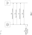
- FIG. 7 is a diagram illustrating an example 700 of IAB topology discovery, in accordance with various aspects of the present disclosure.
- a donor network node and a network node may communicate to establish a connection.
- the donor network node may support a wireless relay network, and the network node may be a relay of the wireless relay network.
- the wireless relay network may be an IAB network.
- the donor network node may be an IAB donor (e.g., an IAB donor gNB) and the network node may be an IAB node in an IAB network of the IAB donor.
- the donor network node may be a first base station (e.g., a first BS 110 ) and the network node may be a second base station (e.g., a second BS 110 ).
- the donor network node may include a CU node (e.g., an IAB donor CU, a gNB CU, and/or the like) and one or more DU nodes (e.g., one or more IAB donor DUs), and the network node may include an MT node (e.g., an IAB MT) and a DU node (e.g., an IAB DU, a gNB DU, and/or the like).
- a CU node e.g., an IAB donor CU, a gNB CU, and/or the like
- DU nodes e.g., one or more IAB donor DUs
- the network node may include an MT node (e.g., an IAB MT
- the MT node may provide an MT function of the network node
- the DU node may provide a DU function of the network node.
- actions described herein as being performed by the CU of the donor network node may be performed by a control plane CU of the donor network node.
- the network node and the donor network node may establish an MT connection. That is, the MT node of the network node and the CU of the donor network node may establish a connection.
- the connection may be an RRC connection.
- the MT node may initiate a connection procedure with the CU, to thereby establish the connection.
- the network node may launch the MT node during an initialization of the network node, and the MT node may initiate a connection procedure with the CU.
- the CU may transmit, via the connection (e.g., RRC connection), a configuration that assigns one or more backhaul adaptation protocol (BAP) addresses for the MT node.
- BAP backhaul adaptation protocol
- a BAP address may be used by the donor network node and the network node for routing packets in the wireless relay network (e.g., IAB network).
- the donor network node may transmit, and the network node may receive, a message including first information associated with a token.
- the CU of the donor network node may transmit, via the connection (e.g., RRC connection) established between the CU and the MT node of the network node, the first information associated with the token to the MT node.
- the token may identify a BAP address of the one or more BAP addresses assigned to the MT node.
- the token may be a BAP address of the one or more BAP addresses assigned to the MT node.
- the network node may store the first information associated with the token for subsequent use by the DU node of the network node (e.g., the DU node may determine that the token is associated with the MT node, and may transmit information associated with the token), as described below.
- the network node may store the first information associated with the token in association with an identifier of the CU. For example, an identifier of the CU received by the MT node during establishment of the connection (e.g., RRC connection) between the CU and the MT node.
- the CU may assign the token to the network node. For example, the CU may generate the token according to a BAP address for the network node, and may store the generated token in association with the MT node. For example, the CU may store the token in association with an identifier of the MT node. The CU may have received the identifier from the MT node, or generated the identifier for the MT node, during establishment of the connection (e.g., RRC connection) between the CU and the MT node.
- the connection e.g., RRC connection
- the network node and the donor network node may establish a DU connection. That is, the DU node of the network node and the CU of the donor network node may establish a connection.
- the DU node may initiate a connection procedure with the CU, to thereby establish the connection.
- the network node may launch the DU node during an initialization of the network node, and the DU node may initiate a connection procedure with the CU.
- the DU node may initiate the connection procedure with the CU after a connection (e.g., RRC connection) between the CU and the MT node of the network node has been established.
- a connection e.g., RRC connection
- the connection between the CU and the DU node may be an F1-C connection.
- the F1-C connection may include an F1 application protocol (F1-AP) connection (e.g., as a top layer of the F1-C connection).
- F1-AP F1 application protocol
- the DU node may initiate an F1-AP connection procedure with the CU.
- the DU node may initiate the F1-AP connection procedure by transmitting an F1-AP setup request message to the CU.
- the network node may transmit, and the donor network node may receive, a message including second information associated with the token.
- the DU node of the network node may transmit the message to the CU of the donor network node.
- the second information associated with the token may correspond to the first information associated with the token that the CU provided to the MT node of the network node.
- the message may be a message of the F1-C connection procedure (e.g., the F1-AP connection procedure), or may be a message associated with another F1-C (e.g., F1-AP) procedure.
- the message may be an F1-AP setup request message (e.g., of an F1-AP connection procedure), an F1-AP DU configuration update message (e.g., of an F1-AP connection procedure or an F1-AP update procedure), an F1-AP status indication message (e.g., of an F1-AP status indication procedure), and/or the like.
- the message may further identify an identifier of the DU node.
- the identifier may be an F1-AP DU identifier for the DU node.
- the DU node may have received the identifier from the CU, or generated the identifier, during establishment of the connection (e.g., F1-AP connection) between the CU and the DU node.
- the donor network node may identify a collocation of the MT node of the network node and the DU node of the network node.
- the CU of the donor network node may identify a collocation of the MT node and the DU node based at least in part on the second information associated with the token that was received from the DU node.
- the CU may compare the first information associated with the token (e.g., that was provided to the MT node), that is stored by the CU, to the second information associated with the token that was received from the DU node.
- the CU may determine that the first information and the second information correspond (e.g., the token provided to the MT node corresponds to the token received from the DU node), to thereby determine that the MT node and the DU node are collocated at the network node.
- the first information and the second information correspond (e.g., the token provided to the MT node corresponds to the token received from the DU node), to thereby determine that the MT node and the DU node are collocated at the network node.
- the CU may store a mapping of an association of the MT node and the DU node. For example, the CU may store a mapping of an identifier of the MT node to an identifier of the DU node. Accordingly, the CU may perform packet routing, resource management, network topology updates, and/or the like, in accordance with the mapping.
- the CU may transmit, and the MT node may receive, a message that includes information for the DU node.
- the CU may transmit the message that includes the information for the DU node, to the MT node, based at least in part on the mapping that associates the MT node and the DU node.
- the CU may assign a resource to the MT node and the DU node based at least in part on the mapping associating the MT node and the DU node.
- the CU may allocate a first portion of the resource for the MT node (e.g., for a wireless link that is to be used by the MT node) and a second portion of the resource for the DU node (e.g., a wireless link that is to be used by the DU node).
- a first portion of the resource for the MT node e.g., for a wireless link that is to be used by the MT node
- a second portion of the resource for the DU node e.g., a wireless link that is to be used by the DU node
- the CU may transmit, and the MT node may receive, a configuration for the DU node.
- the CU may transmit the configuration for the DU node, to the MT node, based at least in part on the mapping associating the MT node and the DU node.
- the CU may transmit the configuration in a message that includes information associated with the token, thereby indicating that the configuration is to be applied to the MT node and the DU node.
- the configuration may identify a routing entry (e.g., a BAP routing entry) for the MT node and the DU node.
- the routing entry may identify a next-hop network node for reaching another network node (e.g., a child network node) of the wireless relay network (e.g., IAB network).
- the MT node may receive (e.g., on a backhaul radio link control (RLC) channel) a packet (e.g., from the DU of the donor network node, from a DU node of a parent network node, and/or the like) that is addressed with a token (e.g., BAP address) associated with the network node.
- RLC radio link control
- the MT node may determine that the token is associated with the network node, to thereby determine that the packet is intended for the network node.
- the packet may be an Internet Protocol (IP) packet
- the DU of the donor network node may have addressed the packet with a token (e.g., BAP address) associated with the network node according to a mapping of IP addresses to tokens (e.g., BAP addresses) stored by the DU of the donor network node.
- a token e.g., BAP address
- the MT node may be associated with an IP address
- the mapping may associate the IP address of the MT node with the token (e.g., BAP address) of the network node.
- the CU may have configured the DU of the donor network node with the mapping based at least in part on assigning the token to the network node.
- the MT node may receive (e.g., on a backhaul RLC channel) a packet (e.g., from the DU of the donor network node, from a DU node of a parent network node, and/or the like) that is addressed with a token (e.g., BAP address) associated with another network node (e.g., a child network node).
- a token e.g., BAP address
- the CU may cause the DU of the donor network node to transmit the packet to the MT node based at least in part on identifying a collocation of the MT node and the DU node, and determining that the DU node is an intermediate hop for the packet.
- the MT node may determine that the token of the packet is not associated with the network node, and provide the packet to the DU node (e.g., in accordance with a routing entry).
- the DU node may forward the packet to a next-hop network node in accordance with a configured routing entry for the DU node, as described above.
- the CU may utilize the mapping associating the MT node and the DU node for routing packets in the wireless relay network (e.g., IAB network).
- FIG. 7 is provided as an example. Other examples may differ from what is described with respect to FIG. 7 .
- FIG. 8 is a diagram illustrating an example process 800 performed, for example, by a network node, in accordance with various aspects of the present disclosure.
- Example process 800 is an example where a network node (e.g., a BS 110 , a UE 120 , an IAB node, and/or the like) performs operations associated with IAB topology discovery.
- a network node e.g., a BS 110 , a UE 120 , an IAB node, and/or the like
- IAB node IAB node
- process 800 may include receiving, via an MT and from a CU of a donor network node, a first message that includes first information associated with a token (block 810 ).
- the network node e.g., using antenna 252 , DEMOD 254 , MIMO detector 256 , receive processor 258 , controller/processor 280 , reception component 1004 , and/or the like
- process 800 may include transmitting, via a DU and to the CU of the donor network node, a second message that includes second information associated with the token, to thereby indicate collocation of the MT and the DU (block 820 ).
- the network node e.g., using controller/processor 240 , transmit processor 220 , TX MIMO processor 230 , MOD 232 , antenna 234 , transmission component 1008 , and/or the like
- Process 800 may include additional aspects, such as any single aspect or any combination of aspects described below and/or in connection with one or more other processes described elsewhere herein.
- the network node is an IAB node.
- the token is a BAP address of the network node.
- the second message further includes an identifier of the DU, and the identifier of the DU node is an F1-AP identifier of the DU.
- process 800 further includes establishing (e.g., using transmit processor 264 , TX MIMO processor 266 , MOD 254 , antenna 252 , DEMOD 254 , MIMO detector 256 , receive processor 258 , controller/processor 280 , memory 282 , reception component 1004 , and/or transmission component 1008 ) an RRC connection to the CU of the donor network node prior to receiving the first message.
- the first message is received via RRC signaling
- the second message is transmitted via F1-AP signaling.
- the second message is an F1-AP setup request message, an F1-AP DU configuration update message, or an F1-AP DU status indication message.
- process 800 further includes receiving (e.g., using antenna 252 , DEMOD 254 , MIMO detector 256 , receive processor 258 , controller/processor 280 , memory 282 , and/or reception component 1004 ), via the MT, a packet addressed with the token.
- receiving e.g., using antenna 252 , DEMOD 254 , MIMO detector 256 , receive processor 258 , controller/processor 280 , memory 282 , and/or reception component 1004 , via the MT, a packet addressed with the token.
- process 800 further includes receiving (e.g., using antenna 252 , DEMOD 254 , MIMO detector 256 , receive processor 258 , controller/processor 280 , memory 282 , and/or reception component 1004 ), via the MT, a packet addressed with another token, and providing the packet to the DU for forwarding to another network node associated with the other token.
- receiving e.g., using antenna 252 , DEMOD 254 , MIMO detector 256 , receive processor 258 , controller/processor 280 , memory 282 , and/or reception component 1004 .
- process 800 further includes receiving (e.g., using antenna 252 , DEMOD 254 , MIMO detector 256 , receive processor 258 , controller/processor 280 , memory 282 , and/or reception component 1004 ), via the MT, a message that includes information for the DU, and providing the information to the DU.
- receiving e.g., using antenna 252 , DEMOD 254 , MIMO detector 256 , receive processor 258 , controller/processor 280 , memory 282 , and/or reception component 1004 .
- process 800 further includes receiving (e.g., using antenna 252 , DEMOD 254 , MIMO detector 256 , receive processor 258 , controller/processor 280 , memory 282 , and/or reception component 1004 ), via the MT, a configuration for the DU, and configuring the DU according to the configuration.
- receiving e.g., using antenna 252 , DEMOD 254 , MIMO detector 256 , receive processor 258 , controller/processor 280 , memory 282 , and/or reception component 1004 .
- process 800 further includes receiving (e.g., using antenna 252 , DEMOD 254 , MIMO detector 256 , receive processor 258 , controller/processor 280 , memory 282 , and/or reception component 1004 ) a configuration that identifies a first portion of a resource that is to be used by the MT node and a second portion of the resource that is to be used by the DU node.
- receiving e.g., using antenna 252 , DEMOD 254 , MIMO detector 256 , receive processor 258 , controller/processor 280 , memory 282 , and/or reception component 1004 .
- process 800 may include additional blocks, fewer blocks, different blocks, or differently arranged blocks than those depicted in FIG. 8 . Additionally, or alternatively, two or more of the blocks of process 800 may be performed in parallel.
- FIG. 9 is a diagram illustrating an example process 900 performed, for example, by a donor network node, in accordance with various aspects of the present disclosure.
- Example process 900 is an example where a donor network node (e.g., a BS 110 , an IAB donor node, a CU, and/or the like) performs operations associated with IAB topology discovery.
- a donor network node e.g., a BS 110 , an IAB donor node, a CU, and/or the like
- IAB donor node e.g., a BS 110 , an IAB donor node, a CU, and/or the like
- process 900 may include receiving, from a DU of a network node, a message that includes information associated with a token (block 910 ).
- the donor network node e.g., using antenna 234 , DEMOD 232 , MIMO detector 236 , receive processor 238 , controller/processor 240 , reception component 1106 , and/or the like
- process 900 may include identifying a collocation of an MT of the network node and the DU based at least in part on the information (block 920 ).
- the donor network node e.g., using controller/processor 240 , determination component 1108 , and/or the like
- Process 900 may include additional aspects, such as any single aspect or any combination of aspects described below and/or in connection with one or more other processes described elsewhere herein.
- process 900 further includes storing a mapping of an identifier of the MT to an identifier of the DU.
- the network node is an IAB node.
- the token is a BAP address of the network node.
- the message further includes an identifier of the DU, and the identifier of the DU is an F1-AP identifier of the DU.
- process 900 further includes establishing (e.g., using transmit processor 220 , TX MIMO processor 230 , modulator 232 , antenna 234 , DEMOD 232 , MIMO detector 236 , receive processor 238 , controller/processor 240 , memory 242 , scheduler 246 , reception component 1106 , and/or transmission component 1104 ) an RRC connection to the network node.
- the second is received via F1-AP signaling.
- the message is an F1-AP setup request message, an F1-AP DU configuration update message, or an F1-AP DU status indication message.
- process 900 further includes transmitting (e.g., using transmit processor 220 , TX MIMO processor 230 , modulator 232 , antenna 234 , controller/processor 240 , memory 242 , scheduler 246 , and/or transmission component 1104 ), to the MT of the network node, a packet addressed with the token.
- transmit processor 220 TX MIMO processor 230 , modulator 232 , antenna 234 , controller/processor 240 , memory 242 , scheduler 246 , and/or transmission component 1104
- process 900 further includes transmitting (e.g., using transmit processor 220 , TX MIMO processor 230 , modulator 232 , antenna 234 , controller/processor 240 , memory 242 , scheduler 246 , and/or transmission component 1104 ), to the MT of the network node, a packet addressed with another token that is to be forwarded by the DU to another network node associated with the other token.
- transmit processor 220 e.g., TX MIMO processor 230 , modulator 232 , antenna 234 , controller/processor 240 , memory 242 , scheduler 246 , and/or transmission component 1104
- process 900 further includes transmitting (e.g., using transmit processor 220 , TX MIMO processor 230 , modulator 232 , antenna 234 , controller/processor 240 , memory 242 , scheduler 246 , and/or transmission component 1104 ), to the MT of the network node, a message that includes information for the DU.
- transmit processor 220 TX MIMO processor 230 , modulator 232 , antenna 234 , controller/processor 240 , memory 242 , scheduler 246 , and/or transmission component 1104
- process 900 further includes transmitting (e.g., using transmit processor 220 , TX MIMO processor 230 , modulator 232 , antenna 234 , controller/processor 240 , memory 242 , scheduler 246 , and/or transmission component 1104 ), to the MT of the network node, a configuration for the DU.
- transmit processor 220 TX MIMO processor 230 , modulator 232 , antenna 234 , controller/processor 240 , memory 242 , scheduler 246 , and/or transmission component 1104
- process 900 further includes transmitting (e.g., using transmit processor 220 , TX MIMO processor 230 , modulator 232 , antenna 234 , controller/processor 240 , memory 242 , scheduler 246 , and/or transmission component 1104 ) a configuration that identifies a first portion of a resource that is to be used by the MT and a second portion of the resource that is to be used by the DU.
- transmit processor 220 e.g., using transmit processor 220 , TX MIMO processor 230 , modulator 232 , antenna 234 , controller/processor 240 , memory 242 , scheduler 246 , and/or transmission component 1104 .
- process 900 further includes transmitting (e.g., using transmit processor 220 , TX MIMO processor 230 , modulator 232 , antenna 234 , controller/processor 240 , memory 242 , scheduler 246 , and/or transmission component 1104 ), to the MT of the network node, another message that includes information associated with the token, and the other message is transmitted via RRC signaling.
- process 900 may include additional blocks, fewer blocks, different blocks, or differently arranged blocks than those depicted in FIG. 9 . Additionally, or alternatively, two or more of the blocks of process 900 may be performed in parallel.
- FIG. 10 is a diagram 1000 illustrating data flow between different modules/means/components in an example apparatus 1002 .
- the apparatus 1002 may be a network node (e.g., a BS 110 , a UE 120 , an IAB node, and/or the like).
- the apparatus 1002 includes a reception component 1004 , an association component 1006 , and/or a transmission component 1008 .
- the reception component 1004 may receive, from a donor network node 1050 (e.g., a BS 110 , an IAB donor node, a CU, and/or the like) and as data 1010 , a first message that includes first information associated with a token. For example, based on establishing a first connection (e.g., an RRC connection) between the apparatus 1002 and the donor network node 1050 , the reception component 1004 may receive the first message that includes the first information associated with the token.
- the reception component 1004 may be associated with an MT node of the apparatus 1002 .
- the association component 1006 may receive, from the reception component 1004 and as data 1012 , information associated with the token.
- the association component 1006 may store the information associated with the token.
- the association component 1006 may store the information associated with the token in association with an identifier of the donor network node 1050 .
- the transmission component 1008 may receive, from the association component 1006 and as data 1014 , information associated with the token. Moreover, the transmission component 1008 may transmit, to the donor network node 1050 and as data 1016 , a second message that includes second information associated with the token. For example, based on establishing a second connection (e.g., an F1-AP connection), or as part of a procedure for establishing the second connection, between the apparatus 1002 and the donor network node 1050 , the transmission component 1008 may transmit the second message that includes the second information associated with the token.
- the transmission component 1008 may be associated with a DU node of the apparatus 1002 .
- the second message that includes the second information associated with the token may provide an indication of a collocation of the reception component 1004 and the transmission component 1008 at the apparatus 1002 .
- the apparatus 1002 may include additional components that perform each of the blocks of the algorithm in the aforementioned process 800 of FIG. 8 , process 900 of FIG. 9 , and/or the like. Each block in the aforementioned process 800 of FIG. 8 , process 900 of FIG. 9 , and/or the like may be performed by a component and the apparatus may include one or more of those components.
- the components may be one or more hardware components specifically configured to carry out the stated processes/algorithm, implemented by a processor configured to perform the stated processes/algorithm, stored within a computer-readable medium for implementation by a processor, or some combination thereof.
- FIG. 10 The number and arrangement of components shown in FIG. 10 are provided as an example. In practice, there may be additional components, fewer components, different components, or differently arranged components than those shown in FIG. 10 . Furthermore, two or more components shown in FIG. 10 may be implemented within a single component, or a single component shown in FIG. 10 may be implemented as multiple, distributed components. Additionally, or alternatively, a set of components (e.g., one or more components) shown in FIG. 10 may perform one or more functions described as being performed by another set of components shown in FIG. 10 .
- FIG. 11 is a diagram 1100 illustrating data flow between different modules/means/components in an example apparatus 1102 .
- the apparatus 1102 may be a donor network node (e.g., a BS 110 , an IAB donor node, a CU, and/or the like).
- the apparatus 1102 includes a transmission component 1104 , a reception component 1106 , and/or determination component 1108 .
- the transmission component 1104 may transmit, to a network node 1150 (e.g., a BS 110 , a UE 120 , an IAB node, and/or the like) and as data 1110 , a first message that includes first information associated with a token. For example, based on establishing a first connection (e.g., an RRC connection) between the apparatus 1102 and the network node 1150 , the transmission component 1104 may transmit the first message that includes the first information associated with the token. The transmission component 1104 may transmit the first message that includes the first information associated with the token to an MT node of the network node 1150 .
- a network node 1150 e.g., a BS 110 , a UE 120 , an IAB node, and/or the like
- a first message that includes first information associated with a token For example, based on establishing a first connection (e.g., an RRC connection) between the apparatus 1102 and the network node 1150 , the transmission
- the reception component 1106 may receive, from the network node 1150 and as data 1112 , a second message that includes second information associated with the token. For example, based on establishing a second connection (e.g., an F1-AP connection), or as part of a procedure for establishing the second connection, between the apparatus 1102 and the network node 1150 , the reception component 1106 may receive the second message that includes the second information associated with the token. The reception component 1106 may receive the second message that includes the second information associated with the token from a DU node of the network node 1150 . In some aspects, the second message may also include an identifier of the DU node.
- a second connection e.g., an F1-AP connection
- the second message may also include an identifier of the DU node.
- the determination component 1108 may receive, from the transmission component 1104 and as data 1114 , information associated with the first message. For example, the determination component 1108 may receive, from the transmission component 1104 , the first information associated with the token. In addition, the determination component 1108 may receive, from the reception component 1106 and as data 1116 , information associated with the second message. For example, the determination component 1108 may receive, from the reception component 1106 , the second information associated with the token. The determination component 1108 may compare the first information associated with the token and the second information associated with the token. Moreover, the determination component 1108 may identify a collocation of the MT node and the DU node at the network node 1150 based at least in part on a determination that the first information corresponds to the second information.
- the apparatus 1102 may include additional components that perform each of the blocks of the algorithm in the aforementioned process 800 of FIG. 8 , process 900 of FIG. 9 , and/or the like. Each block in the aforementioned process 800 of FIG. 8 , process 900 of FIG. 9 , and/or the like may be performed by a component and the apparatus may include one or more of those components.
- the components may be one or more hardware components specifically configured to carry out the stated processes/algorithm, implemented by a processor configured to perform the stated processes/algorithm, stored within a computer-readable medium for implementation by a processor, or some combination thereof.
- FIG. 11 The number and arrangement of components shown in FIG. 11 are provided as an example. In practice, there may be additional components, fewer components, different components, or differently arranged components than those shown in FIG. 11 . Furthermore, two or more components shown in FIG. 11 may be implemented within a single component, or a single component shown in FIG. 11 may be implemented as multiple, distributed components. Additionally, or alternatively, a set of components (e.g., one or more components) shown in FIG. 11 may perform one or more functions described as being performed by another set of components shown in FIG. 11 .
- ком ⁇ онент is intended to be broadly construed as hardware, firmware, and/or a combination of hardware and software.
- a processor is implemented in hardware, firmware, and/or a combination of hardware and software.
- satisfying a threshold may, depending on the context, refer to a value being greater than the threshold, greater than or equal to the threshold, less than the threshold, less than or equal to the threshold, equal to the threshold, not equal to the threshold, and/or the like.
- “at least one of: a, b, or c” is intended to cover a, b, c, a-b, a-c, b-c, and a-b-c, as well as any combination with multiples of the same element (e.g., a-a, a-a-a, a-a-b, a-a-c, a-b-b, a-c-c, b-b, b-b-b, b-b-c, c-c, and c-c-c or any other ordering of a, b, and c).
Landscapes
- Engineering & Computer Science (AREA)
- Computer Networks & Wireless Communication (AREA)
- Signal Processing (AREA)
- Mobile Radio Communication Systems (AREA)
Abstract
Description
Claims (30)
Priority Applications (4)
| Application Number | Priority Date | Filing Date | Title |
|---|---|---|---|
| US17/028,526 US11632704B2 (en) | 2019-09-25 | 2020-09-22 | Techniques for integrated access and backhaul topology discovery |
| PCT/US2020/052168 WO2021061739A1 (en) | 2019-09-25 | 2020-09-23 | Techniques for integrated access and backhaul topology discovery |
| CN202080064661.4A CN114402652B (en) | 2019-09-25 | 2020-09-23 | Techniques for integrated access and backhaul topology discovery |
| EP20811129.4A EP4035494A1 (en) | 2019-09-25 | 2020-09-23 | Techniques for integrated access and backhaul topology discovery |
Applications Claiming Priority (2)
| Application Number | Priority Date | Filing Date | Title |
|---|---|---|---|
| US201962905821P | 2019-09-25 | 2019-09-25 | |
| US17/028,526 US11632704B2 (en) | 2019-09-25 | 2020-09-22 | Techniques for integrated access and backhaul topology discovery |
Publications (2)
| Publication Number | Publication Date |
|---|---|
| US20210092666A1 US20210092666A1 (en) | 2021-03-25 |
| US11632704B2 true US11632704B2 (en) | 2023-04-18 |
Family
ID=74882367
Family Applications (1)
| Application Number | Title | Priority Date | Filing Date |
|---|---|---|---|
| US17/028,526 Active US11632704B2 (en) | 2019-09-25 | 2020-09-22 | Techniques for integrated access and backhaul topology discovery |
Country Status (4)
| Country | Link |
|---|---|
| US (1) | US11632704B2 (en) |
| EP (1) | EP4035494A1 (en) |
| CN (1) | CN114402652B (en) |
| WO (1) | WO2021061739A1 (en) |
Families Citing this family (5)
| Publication number | Priority date | Publication date | Assignee | Title |
|---|---|---|---|---|
| CN115362648B (en) * | 2020-03-16 | 2025-05-09 | 中兴通讯股份有限公司 | Method and device for updating configuration information of downstream devices during inter-host migration |
| EP4085687A4 (en) * | 2020-04-07 | 2023-06-28 | ZTE Corporation | Systems and methods for signaling transmission for sidelink relay communications |
| US20240147346A1 (en) * | 2021-03-18 | 2024-05-02 | Telefonaktiebolaget Lm Ericsson (Publ) | Routing data over a wireless communication link |
| US12075494B2 (en) | 2021-10-22 | 2024-08-27 | Qualcomm Incorporated | Wireless node integration with no distributed unit setup |
| WO2025091494A1 (en) * | 2023-11-03 | 2025-05-08 | Zte Corporation | Supporting relays in integrated access and backhaul networks |
Citations (6)
| Publication number | Priority date | Publication date | Assignee | Title |
|---|---|---|---|---|
| EP3478019A1 (en) | 2017-10-26 | 2019-05-01 | Comcast Cable Communications LLC | Activation and deactivation of configured grant |
| US20210058826A1 (en) * | 2019-09-10 | 2021-02-25 | Intel Corporation | Techniques for integrated access and backhaul (iab) nodes |
| US20210105622A1 (en) * | 2019-08-26 | 2021-04-08 | Samsung Electronics Co., Ltd. | Method and apparatus for authentication of integrated access and backhaul (iab) node in wireless network |
| US20210298000A1 (en) * | 2019-01-09 | 2021-09-23 | Ofinno, Llc | Resource Configuration for Integrated Access and Backhaul Nodes |
| US20210345345A1 (en) * | 2019-01-11 | 2021-11-04 | Huawei Technologies Co., Ltd. | Resource configuration method and apparatus |
| US20210345369A1 (en) * | 2018-09-26 | 2021-11-04 | Telefonaktiebolaget Lm Ericsson (Publ) | Enhanced uplink scheduling in integrated access backhaul (iab) networks |
Family Cites Families (1)
| Publication number | Priority date | Publication date | Assignee | Title |
|---|---|---|---|---|
| CN109803453B (en) * | 2017-11-17 | 2023-07-07 | 华为技术有限公司 | Communication method, communication equipment and communication system thereof |
-
2020
- 2020-09-22 US US17/028,526 patent/US11632704B2/en active Active
- 2020-09-23 WO PCT/US2020/052168 patent/WO2021061739A1/en not_active Ceased
- 2020-09-23 EP EP20811129.4A patent/EP4035494A1/en active Pending
- 2020-09-23 CN CN202080064661.4A patent/CN114402652B/en active Active
Patent Citations (6)
| Publication number | Priority date | Publication date | Assignee | Title |
|---|---|---|---|---|
| EP3478019A1 (en) | 2017-10-26 | 2019-05-01 | Comcast Cable Communications LLC | Activation and deactivation of configured grant |
| US20210345369A1 (en) * | 2018-09-26 | 2021-11-04 | Telefonaktiebolaget Lm Ericsson (Publ) | Enhanced uplink scheduling in integrated access backhaul (iab) networks |
| US20210298000A1 (en) * | 2019-01-09 | 2021-09-23 | Ofinno, Llc | Resource Configuration for Integrated Access and Backhaul Nodes |
| US20210345345A1 (en) * | 2019-01-11 | 2021-11-04 | Huawei Technologies Co., Ltd. | Resource configuration method and apparatus |
| US20210105622A1 (en) * | 2019-08-26 | 2021-04-08 | Samsung Electronics Co., Ltd. | Method and apparatus for authentication of integrated access and backhaul (iab) node in wireless network |
| US20210058826A1 (en) * | 2019-09-10 | 2021-02-25 | Intel Corporation | Techniques for integrated access and backhaul (iab) nodes |
Non-Patent Citations (6)
| Title |
|---|
| Ericsson, "Signaling Aspects of BH RLC Channel and BAP Layer Configuration", Aug. 26-30, 2019, 3GPP TSG-RAN, WG3 Meeting #105, R3-193734, pp. 1-5. (Year: 2019). * |
| International Search Report and Written Opinion——dated Feb. 10, 2021. |
| Nokia, et al, "BAP layer modelling and configuration", Aug. 26-30, 2019, 3GPP TSG-RAN, WG2 Meeting #107 R2-1910038, pp. 1-3. (Year: 2019). * |
| Nokia, et al, "Further details of BAP header and routing", Aug. 26-30, 2019, 3GPP TSG-RAN, WG2 Meeting #107 R2-1910039, pp. 1-3. (Year: 2019). * |
| QUALCOMM: "CR to 38.401 on Integrated Access and Backhaul for NR", 3GPP DRAFT; R3-190188 IAB BASELINE FOR 38401, 3RD GENERATION PARTNERSHIP PROJECT (3GPP), MOBILE COMPETENCE CENTRE ; 650, ROUTE DES LUCIOLES ; F-06921 SOPHIA-ANTIPOLIS CEDEX ; FRANCE, vol. RAN WG3, no. Athens, Greece; 20190215 - 20190301, R3-190188 IAB baseline for 38401, 15 February 2019 (2019-02-15), Mobile Competence Centre ; 650, route des Lucioles ; F-06921 Sophia-Antipolis Cedex ; France , XP051604132 |
| Qualcomm: "CR to 38.401 on Integrated Access and Backhaul for NR,", 3GPP Draft, GPP TSG-RAN WG3 Meeting #103, R3-190188, IAB Baseline for 38401, 3rd Generation Partnership Project (3GPP), Mobile Competence Centre, 650, Route Des Lucioles, F-06921 Sophia-Antipolis Cedex, France, vol. RAN WG3, No. Athens, Greece, Feb. 15, 2019-Mar. 1, 2019, Feb. 15, 2019 (Feb. 15, 2019), XP051604132, 16 Pages, Retrieved from the Internet: URL: http://www.3gpp.org/ftp/tsg%5Fran/WG3%5Flu/TSGR3%5F103/Docs/R3%2D190188%2Ezip. [retrieved on Feb. 15, 2019] the whole document. |
Also Published As
| Publication number | Publication date |
|---|---|
| EP4035494A1 (en) | 2022-08-03 |
| US20210092666A1 (en) | 2021-03-25 |
| CN114402652A (en) | 2022-04-26 |
| CN114402652B (en) | 2024-05-17 |
| WO2021061739A1 (en) | 2021-04-01 |
Similar Documents
| Publication | Publication Date | Title |
|---|---|---|
| US11202222B2 (en) | Quality of service mapping for time-sensitive network traffic in a wireless communication system | |
| US11856623B2 (en) | Relay adaptation layer configuration for a sidelink interface | |
| TWI790247B (en) | Techniques and apparatuses for forwarding in multi-hop wireless networks via multi-layer tunneling and centralized control | |
| US11564280B2 (en) | User equipment to network relay | |
| US20240106796A1 (en) | Management of identifiers in an integrated access and backhaul network | |
| US11632704B2 (en) | Techniques for integrated access and backhaul topology discovery | |
| US11310004B2 (en) | Master node transport network layer information exchange for downlink data forwarding of a secondary node terminated bearer | |
| CN115004770B (en) | Technology for switching between systems from standalone mode to non-standalone mode | |
| US11540211B2 (en) | Techniques for integrated access and backhaul capability indication | |
| US20220141894A1 (en) | Triggering migration to enable inter-donor topology adaptation in a wireless network | |
| US11528654B2 (en) | Transport layer separation in an integrated access and backhaul network | |
| WO2019061265A1 (en) | Techniques and apparatuses for 5g/nr to 4g/lte voice call fallback | |
| WO2022040828A1 (en) | Layer 2 relay initial configuration | |
| TW201933906A (en) | Bandwidth part switch management | |
| US11277783B2 (en) | Low latency relaying of a notification signal in an integrated access and backhaul network | |
| US20230247445A1 (en) | Multiple path support for layer 3 user equipment to network relay | |
| US20230319637A1 (en) | Dual audio channels over dual quality of service flows | |
| US11871276B2 (en) | Central entity routing for integrated access and backhaul deployments |
Legal Events
| Date | Code | Title | Description |
|---|---|---|---|
| FEPP | Fee payment procedure |
Free format text: ENTITY STATUS SET TO UNDISCOUNTED (ORIGINAL EVENT CODE: BIG.); ENTITY STATUS OF PATENT OWNER: LARGE ENTITY |
|
| AS | Assignment |
Owner name: QUALCOMM INCORPORATED, CALIFORNIA Free format text: ASSIGNMENT OF ASSIGNORS INTEREST;ASSIGNORS:HAMPEL, KARL GEORG;LOPES, LUIS FERNANDO BRISSON;ABEDINI, NAVID;AND OTHERS;SIGNING DATES FROM 20210115 TO 20210123;REEL/FRAME:055112/0296 |
|
| STPP | Information on status: patent application and granting procedure in general |
Free format text: DOCKETED NEW CASE - READY FOR EXAMINATION |
|
| STPP | Information on status: patent application and granting procedure in general |
Free format text: NON FINAL ACTION MAILED |
|
| STPP | Information on status: patent application and granting procedure in general |
Free format text: RESPONSE TO NON-FINAL OFFICE ACTION ENTERED AND FORWARDED TO EXAMINER |
|
| STPP | Information on status: patent application and granting procedure in general |
Free format text: FINAL REJECTION MAILED |
|
| STPP | Information on status: patent application and granting procedure in general |
Free format text: RESPONSE AFTER FINAL ACTION FORWARDED TO EXAMINER |
|
| STPP | Information on status: patent application and granting procedure in general |
Free format text: DOCKETED NEW CASE - READY FOR EXAMINATION |
|
| STPP | Information on status: patent application and granting procedure in general |
Free format text: NOTICE OF ALLOWANCE MAILED -- APPLICATION RECEIVED IN OFFICE OF PUBLICATIONS |
|
| STPP | Information on status: patent application and granting procedure in general |
Free format text: AWAITING TC RESP., ISSUE FEE NOT PAID |
|
| STPP | Information on status: patent application and granting procedure in general |
Free format text: DOCKETED NEW CASE - READY FOR EXAMINATION |
|
| STPP | Information on status: patent application and granting procedure in general |
Free format text: NOTICE OF ALLOWANCE MAILED -- APPLICATION RECEIVED IN OFFICE OF PUBLICATIONS |
|
| STCF | Information on status: patent grant |
Free format text: PATENTED CASE |