US11615224B2 - Model generation method - Google Patents
Model generation method Download PDFInfo
- Publication number
- US11615224B2 US11615224B2 US17/098,460 US202017098460A US11615224B2 US 11615224 B2 US11615224 B2 US 11615224B2 US 202017098460 A US202017098460 A US 202017098460A US 11615224 B2 US11615224 B2 US 11615224B2
- Authority
- US
- United States
- Prior art keywords
- model
- matrix
- equation
- static
- bush
- Prior art date
- Legal status (The legal status is an assumption and is not a legal conclusion. Google has not performed a legal analysis and makes no representation as to the accuracy of the status listed.)
- Active, expires
Links
Images


Classifications
-
- G—PHYSICS
- G06—COMPUTING OR CALCULATING; COUNTING
- G06F—ELECTRIC DIGITAL DATA PROCESSING
- G06F30/00—Computer-aided design [CAD]
- G06F30/20—Design optimisation, verification or simulation
-
- G—PHYSICS
- G06—COMPUTING OR CALCULATING; COUNTING
- G06F—ELECTRIC DIGITAL DATA PROCESSING
- G06F30/00—Computer-aided design [CAD]
- G06F30/10—Geometric CAD
- G06F30/15—Vehicle, aircraft or watercraft design
-
- G—PHYSICS
- G01—MEASURING; TESTING
- G01M—TESTING STATIC OR DYNAMIC BALANCE OF MACHINES OR STRUCTURES; TESTING OF STRUCTURES OR APPARATUS, NOT OTHERWISE PROVIDED FOR
- G01M7/00—Vibration-testing of structures; Shock-testing of structures
- G01M7/02—Vibration-testing by means of a shake table
- G01M7/022—Vibration control arrangements, e.g. for generating random vibrations
-
- G—PHYSICS
- G06—COMPUTING OR CALCULATING; COUNTING
- G06F—ELECTRIC DIGITAL DATA PROCESSING
- G06F17/00—Digital computing or data processing equipment or methods, specially adapted for specific functions
- G06F17/10—Complex mathematical operations
- G06F17/16—Matrix or vector computation, e.g. matrix-matrix or matrix-vector multiplication, matrix factorization
-
- G—PHYSICS
- G06—COMPUTING OR CALCULATING; COUNTING
- G06F—ELECTRIC DIGITAL DATA PROCESSING
- G06F30/00—Computer-aided design [CAD]
- G06F30/20—Design optimisation, verification or simulation
- G06F30/23—Design optimisation, verification or simulation using finite element methods [FEM] or finite difference methods [FDM]
-
- G—PHYSICS
- G06—COMPUTING OR CALCULATING; COUNTING
- G06F—ELECTRIC DIGITAL DATA PROCESSING
- G06F2111/00—Details relating to CAD techniques
- G06F2111/10—Numerical modelling
-
- G—PHYSICS
- G06—COMPUTING OR CALCULATING; COUNTING
- G06F—ELECTRIC DIGITAL DATA PROCESSING
- G06F30/00—Computer-aided design [CAD]
- G06F30/20—Design optimisation, verification or simulation
- G06F30/27—Design optimisation, verification or simulation using machine learning, e.g. artificial intelligence, neural networks, support vector machines [SVM] or training a model
-
- Y—GENERAL TAGGING OF NEW TECHNOLOGICAL DEVELOPMENTS; GENERAL TAGGING OF CROSS-SECTIONAL TECHNOLOGIES SPANNING OVER SEVERAL SECTIONS OF THE IPC; TECHNICAL SUBJECTS COVERED BY FORMER USPC CROSS-REFERENCE ART COLLECTIONS [XRACs] AND DIGESTS
- Y02—TECHNOLOGIES OR APPLICATIONS FOR MITIGATION OR ADAPTATION AGAINST CLIMATE CHANGE
- Y02T—CLIMATE CHANGE MITIGATION TECHNOLOGIES RELATED TO TRANSPORTATION
- Y02T90/00—Enabling technologies or technologies with a potential or indirect contribution to GHG emissions mitigation
Definitions
- the disclosure relates to a model generation method for generating a model that reproduces a dynamic response of a part including a member made of a viscoelastic body.
- a suspension bush and an engine mount have been used in a joint between a vehicle suspension and an engine and a vehicle body for the purpose of suppressing transmission of vibration.
- a ride quality of a vehicle it is important to accurately understand a dynamic response of the parts above. Therefore, conventionally, a model for reproducing the dynamic response of the parts has been generated.
- JP 5365356 B discloses a modeling method of a bush (suspension bush) attached to the vehicle suspension (a method of obtaining a bush matrix model).
- the bush is a part configured by providing a viscoelastic body (for example, rubber) that is distorted in accordance with a load between an inner cylinder and an outer cylinder having cylindrical shapes that are substantially coaxial with each other, for example. With this configuration, shock absorption, etc. is possible between parts connected to the inner cylinder and the outer cylinder, respectively.
- modeling is performed by associating a relative displacement between the inner cylinder and the outer cylinder of the bush (components in each direction of X, Y, and Z axes and components in a rotation direction around each axis), or in addition to this, a motion state vector d having velocity, which is a rate of change of the displacement over time, acceleration, and a power of at least second order, as components, with a vector (load vector) F having loads applied to the bush as components (components in each direction of the X, Y, and Z axes and six components of moments around the axes), using a coefficient matrix (hereinafter sometimes simply referred to as a matrix) H as in Equation 1 shown below.
- F Hd Equation 1
- JP 6551320 B discloses, based on the technology of described in JP 5365356 B above, a model generation method to model a deformation history dependence of the viscoelastic body by combining the technology in JP 5365356 B with a generalized Maxwell model such that reproducibility of the dynamic response is realized.
- Characteristics (dynamic response) of a member that is made of a viscoelastic body may change in accordance with an environment temperature when a load is input to the member.
- the inventors of the disclosure focused on that the characteristics of the member change in accordance with the environmental temperature when the load is input to the member, and considered a model generation method that reflects the change in the characteristics.
- the disclosure has been made in view of the above points, and an object of the disclosure is to provide a model generation method that is capable of generating a model corresponding to the environmental temperature as a model that reproduces a dynamic response of a part including a member made of a viscoelastic body.
- Means for solving an issue of the disclosure for achieving the above object is premised on a model generation method for generating a dynamic model that is a model for reproducing a dynamic response of a part including a member made of a viscoelastic body.
- the model generation method is characterized by including: a step of generating a static model in the viscoelastic body for each of environmental temperature conditions; a step of generating a generalized Maxwell model for each of the environmental temperature conditions using the static model; a step of identifying a spring coefficient and a damper viscosity coefficient of the viscoelastic body as a function of a strain rate norm based on a measurement result of a material test piece using a temperature-time conversion rule; a step of identifying an average strain rate of the part as a function of a displacement rate vector; a step of identifying a dynamic spring coefficient and the damper viscosity coefficient of the part as a function of a component of the displacement rate vector; and a step of generating
- a model in accordance with the environmental temperature can be generated as a model for reproducing the dynamic response of the part including the member made of a viscoelastic body. Consequently, highly accurate analysis of the dynamic response that reflects the characteristics changing in accordance with the temperature environment can be performed.
- a relationship between a stress and a strain for each of the environmental temperature conditions is obtained, with a use of the material test piece made of the viscoelastic body, by inputting a load to the material test piece while changing the environmental temperature conditions so as to generate the static model using data of the relationship between the stress and the strain for each of the environmental temperature conditions.
- the static model can be generated based on the data of a test using the actual viscoelastic body. Therefore, highly accurate analysis of the dynamic response in accordance with each environment temperature can be performed as the generalized Maxwell model for analysis.
- the static model in the viscoelastic body that is generated for each of the environmental temperature conditions is a static matrix model
- the generalized Maxwell model is generated for each of the environmental temperature conditions using a matrix of the static matrix model
- the generalized Maxwell model for analysis that can accurately reproduce the direction coupling in addition to the temperature dependence can be generated.
- the generalized Maxwell model is generated using the static model in a viscoelastic body that is generated for each environmental temperature condition, and the generalized Maxwell model for analysis is generated by applying the dynamic spring coefficient and the damper viscosity coefficient that are identified as the function of the component of the displacement rate vector to the generalized Maxwell model thus generated. Therefore, the generalized Maxwell model for analysis corresponding to the environment temperature can be generated as a model that reproduces the dynamic response of the part including the member made of a viscoelastic body, and further, highly accurate analysis of the dynamic response that reflects the characteristics changing in accordance with the temperature environment can be performed.
- FIG. 1 is a diagram showing an example of a generalized Maxwell model
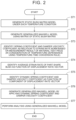
- FIG. 2 is a flowchart showing a processing procedure of a model generation method according to an embodiment
- FIG. 3 is a diagram showing a material test piece
- FIG. 4 is a diagram showing a stress-strain diagram for each environmental temperature, which is a result of a material test
- FIG. 5 is a flowchart showing a procedure for generating a static bush matrix model
- FIG. 6 is a diagram showing the generalized Maxwell model in the embodiment.
- FIG. 7 is a diagram showing an example of a bush
- FIG. 8 is a diagram showing an example of an approximate shape of a bush member
- FIG. 9 A is a diagram showing an example of a method of obtaining a strain rate with respect to a displacement rate based on the approximate shape of the bush member
- FIG. 9 B is a diagram showing an example of a method of obtaining the strain rate with respect to the displacement rate based on the approximate shape of the bush member
- FIG. 9 C is a diagram showing an example of a method of obtaining the strain rate with respect to the displacement rate based on the approximate shape of the bush member
- FIG. 10 is a diagram showing an example of the generalized Maxwell model
- FIG. 11 is a diagram showing an example of a bush
- FIG. 12 is a diagram showing a relationship between displacement of a bush member and a load
- FIG. 13 A is a diagram showing a relationship between displacement of a portion of the bush member and the load.
- FIG. 13 B is a diagram showing a relationship between displacement of other portion of the bush member and the load.
- the model generation method in the following embodiments generates a simulation model capable of responding to a change in a temperature environment taking into account a dependence of a viscoelastic body on the temperature environment in comparison with the model generation method disclosed in JP 6551320 B.
- the model generation method in the following embodiments includes a step of generating a static bush matrix model (static model according to the disclosure) for each of various temperature conditions and generating a generalized Maxwell model using a matrix of the generated static bush matrix model.
- FIG. 1 is a diagram showing an example of the generalized Maxwell model.
- the viscoelastic body is modeled by connecting the dynamic springs 4 - 1 , . . . , 4 -N in parallel to the static spring 1 modeling the elastic body.
- the number N of dynamic springs is appropriately set in accordance with, for example, characteristics of a target viscoelastic body and a required accuracy of the model.
- a displacement vector u represents a relative displacement of an inner cylinder with respect to an outer cylinder of the bush to be modeled, and is defined as a motion state vector.
- Each component value in the coefficient matrix H is calculated such that the bush matrix model, which is the static model, is generated.
- the coefficient matrix H associates the load vector F to be applied to the bush with the displacement vector u as shown in Equation (2) below.
- the displacement vector u includes directional components u x , u y , u z of X, Y, and Z axes and rotational components u rx , u ry , u rz about the respective axes as the components as in Equation (3) below.
- the load vector F includes the component F x , F y , F z in the respective directions of the X, Y, and Z axes and moments M x , M y , M z around the respective axes as the components as shown in Equation (4) below.
- An origin of each axis is, for example, the center of gravity of the bush.
- the coefficient matrix H is a matrix with 6 rows and 6 columns. The component values of the coefficient matrix H can be calculated using, for example, a conventionally known method.
- FIG. 2 is a flowchart showing a processing procedure of the model generation method according to the first embodiment.
- the processing procedure for generating the generalized Maxwell model as a simulation model capable of responding to changes in the temperature environment will be described.
- the processing procedure consists of steps ST 1 to ST 7 shown below.
- step ST 1 the bush matrix model (static bush matrix model) is generated for each temperature condition (environmental temperature condition).
- FIG. 3 shows a material test piece (dumbbell test piece) 10 used in a material test when generating the static bush matrix model for each temperature condition.
- the material test piece 10 is made of the same material as a viscoelastic body (rubber member; hereinafter sometimes simply referred to as a member) used for an actual bush, but has a different size and shape from the member. As shown in FIG. 3 , the material test piece 10 has a total length of about 100 mm and both ends have a constant diameter, while a middle portion has an elongated shape.
- the material test piece 10 is designed to have predetermined size and shape such that measurement tests such as a tensile test and a vibration test are easily conducted with both ends held.
- FIG. 4 is a stress-strain diagram showing a result of each material test when the environmental temperatures are ⁇ 30° C., ⁇ 5° C., 25° C., and 85° C.
- a solid line in FIG. 4 is the stress-strain diagram showing the case where the environmental temperature condition is ⁇ 30° C.
- a broken line in FIG. 4 is the stress-strain diagram showing the case where the environmental temperature condition is ⁇ 5° C.
- FIG. 4 is the stress-strain diagram showing the case where the environmental temperature condition is 25° C.
- a two-dot chain line in FIG. 4 is the stress-strain diagram showing the case where the environmental temperature condition is 85° C.
- the relationships between the stress and the strain greatly differ from each other depending on the environmental temperature conditions. For example, a rate of change in the strain with respect to an amount of increase in the stress increases as the environmental temperature increases.
- the relationship between the stress and the strain has a hysteresis between when the load is increased (loading side) and when the load is decreased (unloading side). The hysteresis increases as the environmental temperature decreases.
- the characteristics of the member made of the viscoelastic body are significantly dependent on the environmental temperature when the load is input to the member.
- step ST 1 data on the relationship between the stress and the strain for each temperature condition is stored in a database of a computer (not shown) that implements the model generation method according to the disclosure.
- the Yeoh model equation is a strain energy density function that is generally used in the analysis of the viscoelastic body, and is known as an equation capable of being accurately approximated in a wide strain region.
- Equation ⁇ 5 ⁇ U C 10 ( I _ 1 - 3 ) + C 2 ⁇ 0 ( I _ 1 - 3 ) 2 + C 3 ⁇ 0 ( I _ 1 - 3 ) 3 + 1 D 1 ⁇ ( J e ⁇ l - 1 ) 2 + 1 D 2 ⁇ ( J e ⁇ l - 1 ) 4 + 1 D 3 ⁇ ( j el - 1 ) 6 ( 5 )
- U Strain ⁇ ⁇ energy ⁇ potential ⁇ C i ⁇ 0 , D i : Material ⁇ parameters ⁇ J el : Elastic ⁇ volume ⁇ ratio ⁇ I 1 _ : First ⁇ invariant ⁇ of ⁇ deviation ⁇ strain
- a finite element method (FEM) model is then constructed using the material parameters C i0 , D i calculated from Equation (5), and the static bush matrix model is generated for each temperature condition by the procedure described below.
- FEM finite element method
- the static bush matrix model is generated by the procedure shown in FIG. 5 .
- the procedure static bush matrix model generation method
- random vibration is assumed to be performed on the FEM model (corresponding to random vibration, in step ST 11 ).
- the random vibration corresponds to vibration in directions other than the six axes, which are the directions of the main axes (X axis, Y axis, Z axis) of the bush and the rotation direction of the main axes. Loads in the axial directions of X-axis, Y-axis, and Z-axis are referred to as F x , F y , and F z , respectively.
- non-random vibration is assumed to be performed on the FEM model (corresponding to non-random vibration, in step ST 12 ).
- the non-random vibration above corresponds to that the bush is vibrated so as to move in the axial directions of the X-axis, the Y-axis, and the Z-axis, and the bush is also vibrated so as to rotate around the respective axes.
- Load data and displacement data of the bush when the random vibration and the non-random vibration are assumed to be performed are then stored (step ST 13 ).
- Equation (6) the relationship between the load applied to the bush and a motion state on assumption that non-random vibration is performed is defined as Equation (6) below, and “relation matrix 1” in Equation (6) is identified using, for example, the least-squares method and a neural network.
- Equation ⁇ 6 ⁇ ( Load ) ( relation ⁇ matrix ⁇ 1 ) ⁇ ( Motion ⁇ state ⁇ 1 ) ( 6 )
- load on the left side of Equation (6) is the matrix of 6 rows and 1 column shown in Equation (4), and configured of the loads F x , F y , F z in the respective directions of the X-axis, the Y-axis, and the Z-axis of the bush and the moments M x , M y , M z of the respective axes.
- “Relation matrix 1” on the right side of Equation (6) is, for example, a coefficient matrix of 6 rows and 18 columns (not shown), and is configured of 108 coefficients.
- “Motion state 1” on the right side of Equation (6) is, for example, a matrix of 18 rows and 1 column (not shown), and is configured of parameters relating to the displacement (for the matrices herein, refer to JP 5365356 B).
- Equation (6) After the load data and the displacement data on assumption that the bush is non-randomly vibrated are obtained, “relation matrix 1” in Equation (6) is identified using the least-squares method and the neural network.
- the load data on assumption that the bush is randomly vibrated is corrected. That is, the corrected load data is obtained by inputting the load data and the displacement data on the assumption that the bush is randomly vibrated to Equation (7) below.
- Equation ⁇ 7 ⁇ ( Corrected load ) ( Load measured with random vibration ) - ( Relation matrix ⁇ 2 ) ⁇ ( Motion ⁇ state measured with ⁇ random vibration ) ( 7 )
- Equation matrix 2 on the right side of Equation (7) is, for example, a coefficient matrix of 6 rows and 18 columns (not shown).
- “Motion state measured with random vibration” on the right side of Equation (7) is, for example, a matrix of 72 rows and 1 column (not shown), and is configured of parameters relating to the displacement (for the matrices herein, refer to JP 5365356 B).
- Equation (8) the relationship between the load and the motion state of the bush when random vibration is assumed is defined as in Equation (8) below so as to identify “relation matrix 2”.
- the corrected load data obtained based on Equation (7) and the stored displacement data when random vibration is assumed are input to Equation (8), and “relation matrix 2” is identified by using, for example, the least-squares method and the neural network.
- Equation ⁇ 8 ⁇ ( Corrected load ) ( Relation matrix ⁇ 2 ) ⁇ ( Function ⁇ of motion ⁇ state measured ⁇ with random vibration ) ( 8 )
- the bush simulation model is defined as in Equation (9) below. That is, the relational equation when the non-random vibration defined using “relation matrix 1” is assumed is added to the relational equation when the random vibration defined using “relation matrix 2” is assumed so as to derive the bush simulation model as shown in Equation (9).
- the first term on the right side represents the main axis characteristic and a shape coupling component of the bush
- the second term represents a coupling compound characteristic due to a compound displacement.
- the shape coupling component is a force generated in a direction that is different from a displacement direction.
- the coupling component due to the compound displacement means that the load-displacement characteristics are changed by the compound displacement in which the axis is displaced while being twisted.
- Equation ⁇ 9 ⁇ ( Load ) ( Relation matrix ⁇ 1 ) ⁇ ( Motion state ⁇ 1 ) + ( Relation matrix ⁇ 2 ) ⁇ ( Function ⁇ of motion ⁇ state measured ⁇ with random vibration ) ( 9 )
- step ST 2 the generalized Maxwell model in which the matrix H in the bush matrix model generated in step ST 1 is used as a spring coefficient matrix is generated.
- an element configuration of springs and dampers of this model is considered as a configuration in which, in the generalized Maxwell model shown in FIG. 1 , the spring coefficient is replaced from a scalar K to the matrix H, and a variable is replaced from the displacement (scalar) to the displacement vector u.
- the viscoelastic body is modeled (the generalized Maxwell model is generated) by connecting the dynamic springs 4 - 1 , . . . , 4 -N in parallel to the static spring 1 modeling the elastic body.
- the number N of the dynamic springs is appropriately set in accordance with, for example, characteristics of a target viscoelastic body and a required accuracy of the model.
- the dynamic spring coefficient ⁇ i and the damper viscosity coefficient C i are identified in the subsequent steps.
- step ST 3 the spring coefficient and the damper viscosity coefficient of a material test piece (in the embodiment, the material test piece is different from the dumbbell test piece described above) are identified as a strain rate norm function based on the measurement results in the material test (dynamic characteristics measurement test) for the material test piece.
- a temperature-time conversion rule is used to identify the function above taking into account the temperature dependence.
- This model has the element configuration of springs and dampers similar to that in the generalized Maxwell model shown in FIG. 6 .
- the dynamic spring coefficient ⁇ i ′ and the damper viscosity coefficient C i ′ of the material test piece are generally expressed as a function of a norm of the strain rate vector v ⁇ as shown by Equations (10) and (11) below. Equation 10 ⁇ i ′(
- Equation (12) is an equation for calculating a temperature-time converter ⁇ r .
- the relaxation time calculated using Equation (13) represents damping characteristics of the viscoelastic body. This makes it possible to improve an accuracy of predicting the characteristics (stress-strain characteristics) of the viscoelastic body when the environmental temperature changes.
- the temperature-time conversion rule using Equations above is known, and for example, the method disclosed in Japanese Unexamined Patent Application Publication No. 2019-159897 (JP 2019-159897 A) can be applied.
- Equation (13) for calculating a relaxation time ⁇ it is possible to reproduce frequency dependence and amplitude dependence at the same time using a power function of a strain rate.
- an average strain rate of the part shape bush is identified as a function of the displacement rate vector. Specifically, the relationship between a displacement rate vector v of the member (temporal change of the displacement vector u) and the strain rate vector v ⁇ at the displacement rate is obtained. Therefore, two assumptions that can be considered physically appropriate are made as shown below. That is, an assumption is made that although the strain of the material in the member is not strictly uniform, the strain is generally uniform except for a local area where the strain is particularly concentrated, and the strain rate vector v ⁇ has a distribution in which the norm of the strain rate vector v ⁇ has a uniform value (average strain rate) regardless of the position (Assumption 1).
- step ST 5 the dynamic spring coefficient ⁇ i ′ and the damper viscosity coefficient C i ′ of the material test piece expressed as a function of the norm of the strain rate vector v ⁇ in step ST 3 are converted to a function of the component of the displacement rate vector v in the member. This can be obtained by substituting the average strain rate of the equation (14) obtained in step ST 4 as the norm of the strain rate vectors of Equations (10), (11).
- the dynamic spring coefficient and the damper viscosity coefficient are considered to be equal, and the dynamic spring coefficient ⁇ i ′ and the damper viscosity coefficient C i ′ of the test piece that are expressed as the function of the component of the displacement rate vector v can be used as the dynamic spring coefficient ⁇ i and the damper viscosity coefficient C i of the member.
- Equations (15), (16) the dynamic characteristic parameter of the member can be obtained based on the test results of the material test piece using the method shown in steps ST 3 to ST 5 .
- Equation 15 ⁇ i ( v ) ⁇ i ′(
- ) ⁇ i ′(
- ) C i ′(
- step ST 6 the dynamic spring coefficient ⁇ i and the damper viscosity coefficient C i obtained in step ST 5 are applied to the generalized Maxwell model generated in step ST 2 so as to complete the generalized Maxwell model (generalized Maxwell model for analysis in the disclosure).
- the generalized Maxwell model generated in step ST 2 is generated based on the static bush matrix model generated for each temperature condition (environmental temperature condition) in step ST 1 . Therefore, the generalized Maxwell model completed in step ST 6 is generated as a simulation model that is capable of coping with changes in the temperature environment. Furthermore, this generalized Maxwell model can accurately reproduce the frequency dependence, the amplitude dependence, and the direction coupling.
- step ST 7 various simulations are performed using the completed generalized Maxwell model so as to analyze the dynamic response of the bush.
- the analysis above can be executed by setting the generalized Maxwell model that is completed as a user-defined element of a general-purpose finite element analysis program, for example.
- the behavior at the time of inputting the relative displacement to the bush may be calculated strictly using the finite element method, etc. However, sufficient accuracy can be ensured by performing an approximate calculation using a simplified method based on a physical consideration as described in each example below.
- FIG. 7 shows an example of a sectional shape taken along a plane (XY plane) that is perpendicular to an axial direction (Z-axis direction) of a bush 20 that is a target of this example.
- the bush 20 has an inner cylinder 21 and an outer cylinder 22 having the same central axis, and a rubber member 23 that is partially provided between the inner cylinder 21 and the outer cylinder 22 .
- the rubber member 23 includes two portions that are arranged symmetrically with respect to the X axis. Each portion has a sectional shape that has a sector shape and is symmetrical with respect to the Y-axis.
- the sectional shape is uniform with respect to the Z-axis.
- a distance between end faces of the rubber member 23 on the inner cylinder 21 side and the outer cylinder 22 side is set to 20 mm, and a height (length in the Z-axis direction) of the rubber member 23 is set to 30 mm.
- each portion of the rubber member 23 is approximated to a rectangular parallelepiped having a surface with a shorter side being 20 mm and a longer side being 30 mm.
- each component of the strain rate vector v ⁇ is expressed by a linear combination of each component of the displacement rate vector v, which results in Equation (17) below.
- the norm of the strain rate vector v ⁇ is specifically calculated based on Equation (17) such that the average strain rate can be expressed using a function of the component of the displacement rate vector as in Equation (18) below. It should be noted that, when Equation (18) is derived, the norm of the strain rate vector is not the magnitude of the vector but the matrix norm when the component is set as the component of a strain rate tensor.
- Example 2 In Example 2, unlike Example 1, calculation is performed based on the result of measuring the actual behavior of the bush. In Example 2, the degree of contribution to the strain rate component due to the rotational speed around each axis is approximated to 0 as in Example 1. Although the similar concept to that in Example 1 is applied, the contribution of the displacement rate component in each axial direction to the strain rate component is generalized as in Equation (19) below with a, b, and c being variables in place of specific values. The norm is calculated based on Equation (19) such that the average strain rate can be expressed using a function of the component of the displacement rate vector as in Equation (20) below. The values of a, b and c can be identified by performing a simple measurement with the actual bush such that the values of a, b, and c are adapted to the measurement results.
- the bush shown in FIG. 7 is an example, and the similar method can be applied to bushes of other shapes.
- the material of the member may be a viscoelastic body other than rubber.
- the relationship between the average strain rate and the displacement rate vector of the bush may be obtained using other methods. For example, under a predetermined condition, the relationship between the average strain rate and the displacement rate vector can be obtained based on the components in the matrix H of the static bush matrix model obtained in step ST 1 .
- a computer including a processor may acquire data such as the measurement results for the material test piece and execute the processing.
- a model taken into account the dependence on the temperature environment is generated in consideration that the dynamic characteristics of the bush using a member of a viscoelastic body such as rubber change in accordance with the temperature environment. Therefore, the model corresponding to the environmental temperature can be generated as a model that reproduces the dynamic response of a part including the member made of a viscoelastic body. Consequently, highly accurate analysis of the dynamic response that reflects the characteristics that change in accordance with the temperature environment can be performed. Further, in the embodiment, a simulation model that is highly accurate and is fast in calculation can be constructed, including the static and dynamic characteristics (frequency dependence, amplitude dependence, pre-strain dependence, direction coupling) and the temperature dependence of the parts (vehicle suspension bush and engine mount).
- step ST 1 the simulation model of the analysis target is derived based on the relationship between the state quantity and the load of the analysis target obtained in both cases of vibrating the FEM model of the analysis target in a specific axial direction and of vibrating the FEM model in various other directions.
- the highly accurate simulation model with small degree of freedom can be constructed.
- the simulation model generated in the embodiment can be applied to the one-dimensional simulation in addition to the three-dimensional simulation. Further, the simulation model can be applied to the full-vehicle simulation and the real-time simulation for vehicles, and can provide a highly accurate simulation model as a simulation such as Software in the Loop Simulation (SILS), Model in the Loop Simulation (MILS), and Hardware in the Loop Simulation (HILS), which can contribute to achievement of fast and more accurate simulation.
- SILS Software in the Loop Simulation
- MILS Model in the Loop Simulation
- HILS Hardware in the Loop Simulation
- Assumption 1 and Assumption 2 above are defined with the entire member as one unit. However, depending on the shape of the member, there may be a case where reproducibility of the model is improved and calculation is made easier if the member is divided into two or more portions for consideration and assumption is made with each divided portion as one unit, rather than making the assumption for the entire member. This method will be described as a second embodiment.
- N dynamic springs are provided for each divided portion of the member that is divided into two or more portions as shown in FIG. 10 , instead of providing N dynamic springs that model the entire member.
- the member is divided into two portions, a first portion and a second portion.
- the dynamic spring 4 - i 1 includes a spring 2 - i 1 and a damper 3 - i 1 corresponding to the dynamic spring coefficient ⁇ i1 and the damper viscosity coefficient C i1 of the first portion, respectively.
- the dynamic spring 4 - i 2 includes a spring 2 - i 2 and a damper 3 - i 2 corresponding to the dynamic spring coefficient ⁇ i2 and the damper viscosity coefficient C i2 of the second portion, respectively.
- FIG. 11 shows an example of a sectional shape taken along a plane (XY plane) that is perpendicular to an axial direction (Z-axis direction) of a bush 30 that is a target of this example.
- the bush 30 has an inner cylinder 31 and an outer cylinder 32 having the same central axis, and a rubber member 33 that is provided between the inner cylinder 31 and the outer cylinder 32 .
- the rubber member 33 is provided with two apertures 34 that are symmetrically with respect to the Y axis.
- FIG. 11 shows an example of a sectional shape taken along a plane (XY plane) that is perpendicular to an axial direction (Z-axis direction) of a bush 30 that is a target of this example.
- the bush 30 has an inner cylinder 31 and an outer cylinder 32 having the same central axis, and a rubber member 33 that is provided between the inner cylinder 31 and the outer cylinder 32 .
- the rubber member 33 is provided with two apertures 34 that are symmetrically with respect
- FIGS. 13 A and 13 B are graphs obtained by dividing the graph in FIG.
- the graph in FIG. 13 A includes a constant inclination regardless of the degree of crush of the apertures 34 .
- the inclination degree is 0 before the apertures 34 are crushed, and the inclination is generated after the apertures 34 are crushed.
- the characteristics of the first portions 33 - 1 and the second portions 33 - 2 are different from each other.
- the dynamic spring coefficients ⁇ i1 , ⁇ i2 and the damper viscosity coefficients C i1 , C i2 are obtained by, for example, expressing the dynamic spring coefficients ⁇ i′ and the damper viscosity coefficient C i ′ of the material test piece using a function of the component of the displacement rate vector v using the different matrices A1, A2, as shown in Equations (21) to (24) below.
- Equations (21) to (24) As described above, calculation of the dynamic parameter for each of the first and second portions having different characteristics makes it possible to facilitate calculation and improve accuracy for approximation. Note that, the graphs shown in FIGS.
- Equation 21 ⁇ i1 ( v ) ⁇ i ′(
- the dynamic spring coefficients ⁇ i1 , ⁇ i2 and the damper viscosity coefficients C i1 , C i2 thus obtained complete the generalized Maxwell model shown in FIG. 10 .
- the dynamic spring is provided corresponding to each portion having different characteristics. Therefore, higher reproducibility can be obtained.
- the member is divided into two portions in the second embodiment, the member may be divided into three or more portions.
- the material parameter of each temperature condition obtained by the equation of the Yeoh model may be obtained in advance from the material test data and stored in the database, without using the equation.
- the model obtained in step ST 1 may not necessarily be the matrix model.
- the static spring 1 of the generalized Maxwell model is replaced with the matrix model.
- the matrix model may be a proxy model of another degenerate method, such as proper orthogonal decomposition (POD) or proper generalized decomposition (PGD), instead of the matrix format.
- POD orthogonal decomposition
- PWD proper generalized decomposition
- the temperature-time conversion rule is used to consider the temperature dependence in step ST 3 of the embodiment above.
- other rules may be applied.
- various methods other than those described above may be applied as the identification method of the material coefficient.
- the exponent m on the right side of Equation (13) of the relaxation time ti is preferably “1”.
- the displacement rate may be converted into the strain rate using a method other than steps ST 3 to ST 7 of the embodiment above.
- the disclosure is useful for modeling dynamic responses of parts such as vehicle bushes, and can be used for, for example, designing high-quality parts.
Landscapes
- Engineering & Computer Science (AREA)
- Physics & Mathematics (AREA)
- Theoretical Computer Science (AREA)
- General Physics & Mathematics (AREA)
- Geometry (AREA)
- Evolutionary Computation (AREA)
- General Engineering & Computer Science (AREA)
- Computer Hardware Design (AREA)
- Mathematical Analysis (AREA)
- Mathematical Physics (AREA)
- Pure & Applied Mathematics (AREA)
- Mathematical Optimization (AREA)
- Computational Mathematics (AREA)
- Data Mining & Analysis (AREA)
- Software Systems (AREA)
- Automation & Control Theory (AREA)
- Aviation & Aerospace Engineering (AREA)
- Medical Informatics (AREA)
- Computing Systems (AREA)
- Computer Vision & Pattern Recognition (AREA)
- Algebra (AREA)
- Artificial Intelligence (AREA)
- Databases & Information Systems (AREA)
- Investigating Strength Of Materials By Application Of Mechanical Stress (AREA)
- Vibration Prevention Devices (AREA)
Abstract
Description
F=Hd Equation 1
γi′(|v ε|) (10)
Equation 11
C i′(|v ε|) (11)
Equation 14
Equation 15
γi(v)≅γi′(|
Equation 16
C i(V)≅C i′(|
γi1(v)≅γi′(|A1v|) (21)
γi2(v)≅γi′(|A2v|) (22)
C i1(v)≅C i′(|A1v|) (23)
Equation 24
C i2(v)≅C i′(|A2v|) (23)
Claims (3)
Applications Claiming Priority (3)
| Application Number | Priority Date | Filing Date | Title |
|---|---|---|---|
| JPJP2020-027353 | 2020-02-20 | ||
| JP2020-027353 | 2020-02-20 | ||
| JP2020027353A JP7310641B2 (en) | 2020-02-20 | 2020-02-20 | Model generation method |
Publications (2)
| Publication Number | Publication Date |
|---|---|
| US20210264074A1 US20210264074A1 (en) | 2021-08-26 |
| US11615224B2 true US11615224B2 (en) | 2023-03-28 |
Family
ID=77275278
Family Applications (1)
| Application Number | Title | Priority Date | Filing Date |
|---|---|---|---|
| US17/098,460 Active 2041-05-25 US11615224B2 (en) | 2020-02-20 | 2020-11-16 | Model generation method |
Country Status (3)
| Country | Link |
|---|---|
| US (1) | US11615224B2 (en) |
| JP (1) | JP7310641B2 (en) |
| CN (1) | CN113283002A (en) |
Families Citing this family (4)
| Publication number | Priority date | Publication date | Assignee | Title |
|---|---|---|---|---|
| JP7647436B2 (en) | 2021-08-11 | 2025-03-18 | 株式会社デンソー | Signal generating device, signal generating program, and signal generating method |
| CN113705097B (en) * | 2021-08-30 | 2024-04-02 | 广州文远知行科技有限公司 | Vehicle model construction method and device, computer equipment and storage medium |
| JPWO2024247832A1 (en) | 2023-05-30 | 2024-12-05 | ||
| CN118013741A (en) * | 2024-02-20 | 2024-05-10 | 郑州大学 | Paste structure model construction, strain transfer rate calculation and dynamic response test method |
Citations (5)
| Publication number | Priority date | Publication date | Assignee | Title |
|---|---|---|---|---|
| JP2010286377A (en) | 2009-06-12 | 2010-12-24 | Toyota Motor Corp | Model generation method |
| JP2014010047A (en) | 2012-06-29 | 2014-01-20 | Nitto Denko Corp | Program for outputting stress/strain curve equation and its device and method for evaluating physical property of elastic material |
| JP6048358B2 (en) | 2013-10-08 | 2016-12-21 | トヨタ自動車株式会社 | Analysis device |
| JP6551320B2 (en) | 2016-06-15 | 2019-07-31 | トヨタ自動車株式会社 | Model generation method |
| US20190285610A1 (en) | 2018-03-14 | 2019-09-19 | Toyota Jidosha Kabushiki Kaisha | Analysis apparatus |
Family Cites Families (4)
| Publication number | Priority date | Publication date | Assignee | Title |
|---|---|---|---|---|
| JP2007093596A (en) | 2005-08-31 | 2007-04-12 | Chinontec Kk | Relaxation modulus measurement method, relaxation modulus measurement program, recording medium storing the program, and mold manufacturing method |
| JP2015032295A (en) | 2013-08-07 | 2015-02-16 | ヤマハ株式会社 | Damped vibration analysis method |
| CN106802969B (en) | 2015-11-26 | 2020-08-07 | 英业达科技有限公司 | Verification system and verification method for dynamic characteristics of damping material |
| CN110188451B (en) * | 2019-05-27 | 2023-04-25 | 华东理工大学 | Analysis method for residual stress of polyethylene pipe welding joint |
-
2020
- 2020-02-20 JP JP2020027353A patent/JP7310641B2/en active Active
- 2020-11-12 CN CN202011262600.7A patent/CN113283002A/en active Pending
- 2020-11-16 US US17/098,460 patent/US11615224B2/en active Active
Patent Citations (7)
| Publication number | Priority date | Publication date | Assignee | Title |
|---|---|---|---|---|
| JP2010286377A (en) | 2009-06-12 | 2010-12-24 | Toyota Motor Corp | Model generation method |
| JP5365356B2 (en) | 2009-06-12 | 2013-12-11 | トヨタ自動車株式会社 | Model generation method |
| JP2014010047A (en) | 2012-06-29 | 2014-01-20 | Nitto Denko Corp | Program for outputting stress/strain curve equation and its device and method for evaluating physical property of elastic material |
| JP6048358B2 (en) | 2013-10-08 | 2016-12-21 | トヨタ自動車株式会社 | Analysis device |
| JP6551320B2 (en) | 2016-06-15 | 2019-07-31 | トヨタ自動車株式会社 | Model generation method |
| US20190285610A1 (en) | 2018-03-14 | 2019-09-19 | Toyota Jidosha Kabushiki Kaisha | Analysis apparatus |
| JP2019159897A (en) | 2018-03-14 | 2019-09-19 | トヨタ自動車株式会社 | Analyzer |
Non-Patent Citations (3)
| Title |
|---|
| Bódai G, Goda T. A new, tensile test-based parameter identification method for large-strain generalized Maxwell-model. Acta Polytechnica Hungarica. Jan. 1, 2011;8(5):89-108. (Year: 2011). * |
| Park SW. Analytical modeling of viscoelastic dampers for structural and vibration control. International Journal of Solids and structures. Nov. 1, 2001;38(44-45):8065-92. (Year: 2001). * |
| Ucar H, Basdogan I. Dynamic characterization and modeling of rubber shock absorbers: A comprehensive case study. Journal of Low Frequency Noise, Vibration and Active Control. Sep. 2018;37(3):509-18. (Year: 2018). * |
Also Published As
| Publication number | Publication date |
|---|---|
| JP7310641B2 (en) | 2023-07-19 |
| CN113283002A (en) | 2021-08-20 |
| JP2021131330A (en) | 2021-09-09 |
| US20210264074A1 (en) | 2021-08-26 |
Similar Documents
| Publication | Publication Date | Title |
|---|---|---|
| US11615224B2 (en) | Model generation method | |
| Lee et al. | Prediction of the dynamic equivalent stiffness for a rubber bushing using the finite element method and empirical modeling | |
| JP6408856B2 (en) | Method for simulating polymer materials | |
| CN103324825B (en) | Method for Evaluating Energy Loss of High Polymer Materials | |
| CN107679301A (en) | A kind of segmented heavy duty crossbeam scale model design method | |
| US7308387B1 (en) | Method and system for numerically simulating foam-like material in finite element analysis | |
| Maassen et al. | Modeling of the Split-Hopkinson-Pressure-Bar experiment with the explicit material point method | |
| EP2677446A2 (en) | Method for simulating Polymer material | |
| Gao et al. | Programmed load spectrum for fatigue bench test of a vehicle body | |
| Ikechukwu et al. | Experimental modal analysis of a flat plate subjected to vibration | |
| US7130748B2 (en) | Simulation method for estimating performance of product made of viscoelastic material | |
| Azizi et al. | Prediction and verification of the periodic response of a single-degree-of-freedom foam-mass system by using incremental harmonic balance | |
| JP6551320B2 (en) | Model generation method | |
| CN119670249A (en) | Vehicle impact strength analysis method, system, device and readable storage medium | |
| Farahani et al. | Modal Analysis of a Non-rotating Inflated Tire using Experimental and Numerical Methods | |
| Locke et al. | Applying uncertainty quantification to structural systems: parameter reduction for evaluating model complexity | |
| Banks et al. | Stress-strain laws for carbon black and silicon filled elastomers | |
| US20130179132A1 (en) | Analysis Method, Apparatus and Software for a System With Frequency Dependent Materials | |
| Yıldırım et al. | Harmonic response analysis of double bridge crane system on multi carriages | |
| Xiao et al. | Quantitative Analysis of Load Characteristics of Six-Axis Force/Torque Sensor for Robots Based on Dynamic Model | |
| Schneider et al. | Digital validation of cable performance for vehicles in operation | |
| JP2003139669A (en) | Simulation method for predicting performance of product composed of viscoelastic material | |
| Cimrman et al. | Higher‐order inverse mass matrices for the explicit transient analysis of heterogeneous solids | |
| Sandbrook | Verification of a Reduced-Order Extension Spring Model | |
| Zhang et al. | FE‐Meshfree QUAD4 Element with Modified Radial Point Interpolation Function for Structural Dynamic Analysis |
Legal Events
| Date | Code | Title | Description |
|---|---|---|---|
| AS | Assignment |
Owner name: TOYOTA JIDOSHA KABUSHIKI KAISHA, JAPAN Free format text: ASSIGNMENT OF ASSIGNORS INTEREST;ASSIGNOR:ITO, SATOSHI;REEL/FRAME:054369/0402 Effective date: 20200923 |
|
| FEPP | Fee payment procedure |
Free format text: ENTITY STATUS SET TO UNDISCOUNTED (ORIGINAL EVENT CODE: BIG.); ENTITY STATUS OF PATENT OWNER: LARGE ENTITY |
|
| STPP | Information on status: patent application and granting procedure in general |
Free format text: DOCKETED NEW CASE - READY FOR EXAMINATION |
|
| STPP | Information on status: patent application and granting procedure in general |
Free format text: NON FINAL ACTION MAILED |
|
| STPP | Information on status: patent application and granting procedure in general |
Free format text: RESPONSE TO NON-FINAL OFFICE ACTION ENTERED AND FORWARDED TO EXAMINER |
|
| STPP | Information on status: patent application and granting procedure in general |
Free format text: NOTICE OF ALLOWANCE MAILED -- APPLICATION RECEIVED IN OFFICE OF PUBLICATIONS |
|
| STCF | Information on status: patent grant |
Free format text: PATENTED CASE |