US11602640B2 - Irradiation device with adjustable beam angle - Google Patents
Irradiation device with adjustable beam angle Download PDFInfo
- Publication number
- US11602640B2 US11602640B2 US16/875,991 US202016875991A US11602640B2 US 11602640 B2 US11602640 B2 US 11602640B2 US 202016875991 A US202016875991 A US 202016875991A US 11602640 B2 US11602640 B2 US 11602640B2
- Authority
- US
- United States
- Prior art keywords
- irradiation device
- longitudinal shell
- radiation source
- lenses
- radiation
- Prior art date
- Legal status (The legal status is an assumption and is not a legal conclusion. Google has not performed a legal analysis and makes no representation as to the accuracy of the status listed.)
- Active, expires
Links
- 230000005855 radiation Effects 0.000 claims abstract description 91
- 230000005670 electromagnetic radiation Effects 0.000 claims abstract description 30
- 230000007246 mechanism Effects 0.000 claims abstract description 23
- 230000003287 optical effect Effects 0.000 claims abstract description 6
- 238000001228 spectrum Methods 0.000 claims description 6
- 239000000203 mixture Substances 0.000 claims description 5
- 239000000758 substrate Substances 0.000 claims description 4
- 239000000463 material Substances 0.000 description 12
- 238000010276 construction Methods 0.000 description 6
- 238000005516 engineering process Methods 0.000 description 6
- 238000005286 illumination Methods 0.000 description 5
- 230000001225 therapeutic effect Effects 0.000 description 5
- 230000004907 flux Effects 0.000 description 4
- 238000004519 manufacturing process Methods 0.000 description 4
- 239000004033 plastic Substances 0.000 description 4
- 239000004065 semiconductor Substances 0.000 description 4
- 229910052782 aluminium Inorganic materials 0.000 description 3
- XAGFODPZIPBFFR-UHFFFAOYSA-N aluminium Chemical compound [Al] XAGFODPZIPBFFR-UHFFFAOYSA-N 0.000 description 3
- 238000000034 method Methods 0.000 description 3
- 238000012986 modification Methods 0.000 description 3
- 230000004048 modification Effects 0.000 description 3
- 230000000007 visual effect Effects 0.000 description 3
- 208000002874 Acne Vulgaris Diseases 0.000 description 2
- OAICVXFJPJFONN-UHFFFAOYSA-N Phosphorus Chemical compound [P] OAICVXFJPJFONN-UHFFFAOYSA-N 0.000 description 2
- 206010000496 acne Diseases 0.000 description 2
- JNDMLEXHDPKVFC-UHFFFAOYSA-N aluminum;oxygen(2-);yttrium(3+) Chemical compound [O-2].[O-2].[O-2].[Al+3].[Y+3] JNDMLEXHDPKVFC-UHFFFAOYSA-N 0.000 description 2
- 238000000576 coating method Methods 0.000 description 2
- 239000003086 colorant Substances 0.000 description 2
- 230000009849 deactivation Effects 0.000 description 2
- 230000004313 glare Effects 0.000 description 2
- 229910052738 indium Inorganic materials 0.000 description 2
- APFVFJFRJDLVQX-UHFFFAOYSA-N indium atom Chemical compound [In] APFVFJFRJDLVQX-UHFFFAOYSA-N 0.000 description 2
- 238000009434 installation Methods 0.000 description 2
- 230000003902 lesion Effects 0.000 description 2
- 239000004417 polycarbonate Substances 0.000 description 2
- 229920000515 polycarbonate Polymers 0.000 description 2
- 229920000642 polymer Polymers 0.000 description 2
- 230000008569 process Effects 0.000 description 2
- 229910019901 yttrium aluminum garnet Inorganic materials 0.000 description 2
- PFNQVRZLDWYSCW-UHFFFAOYSA-N (fluoren-9-ylideneamino) n-naphthalen-1-ylcarbamate Chemical compound C12=CC=CC=C2C2=CC=CC=C2C1=NOC(=O)NC1=CC=CC2=CC=CC=C12 PFNQVRZLDWYSCW-UHFFFAOYSA-N 0.000 description 1
- 208000032484 Accidental exposure to product Diseases 0.000 description 1
- ZOXJGFHDIHLPTG-UHFFFAOYSA-N Boron Chemical compound [B] ZOXJGFHDIHLPTG-UHFFFAOYSA-N 0.000 description 1
- RYGMFSIKBFXOCR-UHFFFAOYSA-N Copper Chemical compound [Cu] RYGMFSIKBFXOCR-UHFFFAOYSA-N 0.000 description 1
- 229910052693 Europium Inorganic materials 0.000 description 1
- 229910002601 GaN Inorganic materials 0.000 description 1
- 229910005540 GaP Inorganic materials 0.000 description 1
- GYHNNYVSQQEPJS-UHFFFAOYSA-N Gallium Chemical compound [Ga] GYHNNYVSQQEPJS-UHFFFAOYSA-N 0.000 description 1
- JMASRVWKEDWRBT-UHFFFAOYSA-N Gallium nitride Chemical compound [Ga]#N JMASRVWKEDWRBT-UHFFFAOYSA-N 0.000 description 1
- UFHFLCQGNIYNRP-UHFFFAOYSA-N Hydrogen Chemical compound [H][H] UFHFLCQGNIYNRP-UHFFFAOYSA-N 0.000 description 1
- FYYHWMGAXLPEAU-UHFFFAOYSA-N Magnesium Chemical compound [Mg] FYYHWMGAXLPEAU-UHFFFAOYSA-N 0.000 description 1
- 208000007101 Muscle Cramp Diseases 0.000 description 1
- 201000002481 Myositis Diseases 0.000 description 1
- 206010052143 Ocular discomfort Diseases 0.000 description 1
- XUIMIQQOPSSXEZ-UHFFFAOYSA-N Silicon Chemical compound [Si] XUIMIQQOPSSXEZ-UHFFFAOYSA-N 0.000 description 1
- 208000005392 Spasm Diseases 0.000 description 1
- 206010052428 Wound Diseases 0.000 description 1
- 208000027418 Wounds and injury Diseases 0.000 description 1
- HCHKCACWOHOZIP-UHFFFAOYSA-N Zinc Chemical compound [Zn] HCHKCACWOHOZIP-UHFFFAOYSA-N 0.000 description 1
- 239000005083 Zinc sulfide Substances 0.000 description 1
- 231100000818 accidental exposure Toxicity 0.000 description 1
- 239000000654 additive Substances 0.000 description 1
- 230000032683 aging Effects 0.000 description 1
- AJGDITRVXRPLBY-UHFFFAOYSA-N aluminum indium Chemical compound [Al].[In] AJGDITRVXRPLBY-UHFFFAOYSA-N 0.000 description 1
- 229920001222 biopolymer Polymers 0.000 description 1
- 229910052796 boron Inorganic materials 0.000 description 1
- 230000008859 change Effects 0.000 description 1
- 238000009500 colour coating Methods 0.000 description 1
- 150000001875 compounds Chemical class 0.000 description 1
- 229910052802 copper Inorganic materials 0.000 description 1
- 239000010949 copper Substances 0.000 description 1
- 239000002537 cosmetic Substances 0.000 description 1
- 230000007423 decrease Effects 0.000 description 1
- 230000007812 deficiency Effects 0.000 description 1
- 238000000151 deposition Methods 0.000 description 1
- 238000002059 diagnostic imaging Methods 0.000 description 1
- 238000009826 distribution Methods 0.000 description 1
- OGPBJKLSAFTDLK-UHFFFAOYSA-N europium atom Chemical compound [Eu] OGPBJKLSAFTDLK-UHFFFAOYSA-N 0.000 description 1
- 229910052733 gallium Inorganic materials 0.000 description 1
- HZXMRANICFIONG-UHFFFAOYSA-N gallium phosphide Chemical compound [Ga]#P HZXMRANICFIONG-UHFFFAOYSA-N 0.000 description 1
- 239000011521 glass Substances 0.000 description 1
- 229910052736 halogen Inorganic materials 0.000 description 1
- 150000002367 halogens Chemical class 0.000 description 1
- 229910052739 hydrogen Inorganic materials 0.000 description 1
- 239000001257 hydrogen Substances 0.000 description 1
- 230000004054 inflammatory process Effects 0.000 description 1
- 238000002347 injection Methods 0.000 description 1
- 239000007924 injection Substances 0.000 description 1
- 229910052500 inorganic mineral Inorganic materials 0.000 description 1
- 239000011777 magnesium Substances 0.000 description 1
- 229910052749 magnesium Inorganic materials 0.000 description 1
- 230000003211 malignant effect Effects 0.000 description 1
- 239000011707 mineral Substances 0.000 description 1
- 229910052754 neon Inorganic materials 0.000 description 1
- GKAOGPIIYCISHV-UHFFFAOYSA-N neon atom Chemical compound [Ne] GKAOGPIIYCISHV-UHFFFAOYSA-N 0.000 description 1
- 150000004767 nitrides Chemical class 0.000 description 1
- 230000010287 polarization Effects 0.000 description 1
- 239000002861 polymer material Substances 0.000 description 1
- -1 potassium fluorosilicate Chemical compound 0.000 description 1
- 229910052710 silicon Inorganic materials 0.000 description 1
- 239000010703 silicon Substances 0.000 description 1
- 239000007787 solid Substances 0.000 description 1
- 239000010409 thin film Substances 0.000 description 1
- 230000029663 wound healing Effects 0.000 description 1
- 229910052725 zinc Inorganic materials 0.000 description 1
- 239000011701 zinc Substances 0.000 description 1
- 229910052984 zinc sulfide Inorganic materials 0.000 description 1
- DRDVZXDWVBGGMH-UHFFFAOYSA-N zinc;sulfide Chemical compound [S-2].[Zn+2] DRDVZXDWVBGGMH-UHFFFAOYSA-N 0.000 description 1
Images


Classifications
-
- A—HUMAN NECESSITIES
- A61—MEDICAL OR VETERINARY SCIENCE; HYGIENE
- A61N—ELECTROTHERAPY; MAGNETOTHERAPY; RADIATION THERAPY; ULTRASOUND THERAPY
- A61N5/00—Radiation therapy
- A61N5/06—Radiation therapy using light
-
- A—HUMAN NECESSITIES
- A61—MEDICAL OR VETERINARY SCIENCE; HYGIENE
- A61N—ELECTROTHERAPY; MAGNETOTHERAPY; RADIATION THERAPY; ULTRASOUND THERAPY
- A61N5/00—Radiation therapy
- A61N5/06—Radiation therapy using light
- A61N2005/0632—Constructional aspects of the apparatus
-
- A—HUMAN NECESSITIES
- A61—MEDICAL OR VETERINARY SCIENCE; HYGIENE
- A61N—ELECTROTHERAPY; MAGNETOTHERAPY; RADIATION THERAPY; ULTRASOUND THERAPY
- A61N5/00—Radiation therapy
- A61N5/06—Radiation therapy using light
- A61N2005/065—Light sources therefor
- A61N2005/0651—Diodes
- A61N2005/0652—Arrays of diodes
-
- A—HUMAN NECESSITIES
- A61—MEDICAL OR VETERINARY SCIENCE; HYGIENE
- A61N—ELECTROTHERAPY; MAGNETOTHERAPY; RADIATION THERAPY; ULTRASOUND THERAPY
- A61N5/00—Radiation therapy
- A61N5/06—Radiation therapy using light
- A61N2005/065—Light sources therefor
- A61N2005/0651—Diodes
- A61N2005/0653—Organic light emitting diodes
-
- A—HUMAN NECESSITIES
- A61—MEDICAL OR VETERINARY SCIENCE; HYGIENE
- A61N—ELECTROTHERAPY; MAGNETOTHERAPY; RADIATION THERAPY; ULTRASOUND THERAPY
- A61N5/00—Radiation therapy
- A61N5/06—Radiation therapy using light
- A61N2005/0658—Radiation therapy using light characterised by the wavelength of light used
- A61N2005/0659—Radiation therapy using light characterised by the wavelength of light used infrared
-
- A—HUMAN NECESSITIES
- A61—MEDICAL OR VETERINARY SCIENCE; HYGIENE
- A61N—ELECTROTHERAPY; MAGNETOTHERAPY; RADIATION THERAPY; ULTRASOUND THERAPY
- A61N5/00—Radiation therapy
- A61N5/06—Radiation therapy using light
- A61N2005/0658—Radiation therapy using light characterised by the wavelength of light used
- A61N2005/0661—Radiation therapy using light characterised by the wavelength of light used ultraviolet
-
- A—HUMAN NECESSITIES
- A61—MEDICAL OR VETERINARY SCIENCE; HYGIENE
- A61N—ELECTROTHERAPY; MAGNETOTHERAPY; RADIATION THERAPY; ULTRASOUND THERAPY
- A61N5/00—Radiation therapy
- A61N5/06—Radiation therapy using light
- A61N2005/0658—Radiation therapy using light characterised by the wavelength of light used
- A61N2005/0662—Visible light
Definitions
- the present invention relates generally to devices capable of generating and disseminating radiation in Ultra-Violet (UV), visible light, and infrared frequencies of the electromagnetic spectrum. More specifically, the present invention relates to irradiation devices capable of achieving emissions of the radiations with variable beam angles.
- UV Ultra-Violet
- visible light visible light
- infrared frequencies of the electromagnetic spectrum.
- the present invention relates to irradiation devices capable of achieving emissions of the radiations with variable beam angles.
- Irradiation devices can be used for several applications based on the wavelengths ( ⁇ ) and frequencies (v) at which such devices emit electromagnetic radiation. They can be used in medical imaging when configured to emit X-Rays ( ⁇ varying between 0.1 to 10 nm), for cosmetic and non-invasive therapeutic applications when configured for Infrared radiation ( ⁇ varying between 700 nm to 1 mm) or red light ( ⁇ varying between 625 to 740 nm) or blue light ( ⁇ varying between 450 to 485 nm) or even some cases UV radiation ( ⁇ varying between 10 to 400 nm). Also, they can be used for spatial lighting purposes when configured to emit wide spectrum visible light ( ⁇ varying between 380 to 740 nm). Different types of irradiation devices are available in the market e.g. lasers, incandescent lamps, compact fluorescent lamps, halogen lamps, Light Emitting Diodes (LEDs) based lamps, fluorescent tube lights, and neon lamps, etc.
- LEDs Light Emitting Diodes
- a point in the plane just opposite of the irradiation device receives greater intensity, as compared to a point that subtends an angle at the irradiation device as the radiation reaching that point is traveling a longer distance when compared to the point that is just opposite the irradiation device.
- the angle subtended at the irradiation device is called a beam angle or beam spread.
- the beam angle is an important metric in determining effective dosage received by a patient located at a given distance from the irradiation device, in medical applications. Also, the beam angle is used as an essential metric in determining illumination of a surface located at a given distance from the irradiation device in spatial lighting applications.
- An improper beam angle of the irradiation can cause several problems such as improper dosage and ineffective treatment in therapeutic applications and insufficient lighting, glare problem, improper contrast, visual discomfort, and reflections on work surfaces (for example, computer screens) in spatial lighting applications.
- Conventionally available irradiation devices have had a fixed beam angle, therefore in applications where more than one beam angle of the irradiation is required, multiple irradiation devices of different corresponding beam angles had to be used.
- some of the irradiation devices use reflective optic members provided in the irradiation devices to control the beam angle of the emitted radiation, however, the use of the reflective optic members in the irradiation device makes the operation of the irradiation device more complex and cost-intensive.
- the plurality of lenses be selected on factors such as a particular beam angle, intensity of electromagnetic radiation, spot size in terms of length of the diameter of the spot created, a distance of the spot from the irradiation device, the intensity of the illumination at the location of the spot, a type of electromagnetic radiation source being used and other factors;
- an irradiation device capable of emitting electromagnetic radiation at variable beam angles
- the irradiation device comprising a housing assembly including a longitudinal shell, the longitudinal shell having a first end and a second end, a first end cap assembly provided at the first end of the longitudinal shell, and a second end cap assembly provided at the second end of the longitudinal shell, a rotate and lock mechanism adapted to allow rotational adjustment of the longitudinal shell, a plurality of lenses provided along with the longitudinal shell, wherein each one of the plurality of lenses has a distinct set of optical characteristics when compared with other lenses of the plurality of lenses and a radiation source configured to emit electromagnetic radiation, provided within the longitudinal shell.
- the rotate and lock mechanism is constituted by a spring element and a contact element attached with the first end in the first end cap assembly, and a pair of meshing sets of teeth, wherein a first set of teeth of the pair, is provided at the second end of the longitudinal shell and a second set of teeth of the pair, is provided at an inner surface of the second end cap assembly.
- the radiation source is configured to be deactivated during the rotation of the longitudinal shell.
- the rotate and lock mechanism includes a first electrical actuator with a self-locking shaft, provided within the first end cap assembly.
- the radiation source is capable of rotating within the longitudinal shell.
- the irradiation device further comprises a second rotate and lock mechanism including a second electrical actuator with a second self-locking shaft, the second rotate and lock mechanism adapted to cause the rotational adjustment of the radiation source.
- the radiation source is configured to be deactivated during the rotation of the radiation source.
- the plurality of lenses includes a convex lens, a concave lens, and a Fresnel lens.
- the radiation source is configured to emit electromagnetic radiation in Ultra-Violet (UV), visible light, and Infrared (IR) wavelengths bands of the electromagnetic spectrum.
- UV Ultra-Violet
- IR Infrared
- the radiation source is configured to emit electromagnetic radiation in any one of a pulse mode and continuous mode.
- the radiation source includes one or more Light Emitting Diodes (LEDs).
- LEDs Light Emitting Diodes
- the one or more LEDs have been provided on an Organic LED (OLED) based flexible panel or an inorganic LED based flexible panel.
- OLED Organic LED
- the one or more LEDs are provided as a printable composition of micro-LEDs, printed on a substrate.
- FIG. 1 A illustrates an exploded view of an irradiation device capable of emitting electromagnetic radiation at variable beam angles, in accordance with an embodiment of the present invention
- FIG. 1 B illustrates a sectional view of the irradiation device of FIG. 1 A , with a rotate and lock mechanism in an engaged position;
- FIG. 1 C illustrates a sectional view of the irradiation device of FIG. 1 A , with the rotate and lock mechanism in a disengaged position;
- FIG. 2 illustrates a visual representation of a rotational adjustment of a longitudinal shell of the irradiation device of FIG. 1 A ;
- FIG. 3 illustrates a sectional view of the irradiation device capable of emitting electromagnetic radiation at variable beam angles, in accordance with another embodiment of the present invention
- FIG. 4 A illustrates a sectional view of the irradiation device of FIG. 3 , sectioned along a plane A-A;
- FIG. 4 B illustrates a sectional view of the irradiation device of FIG. 3 , sectioned along a plane B-B;
- FIG. 5 illustrates an exploded view of the irradiation device of FIG. 3 ;
- FIG. 6 illustrates a cross-sectional view of the irradiation device of FIG. 3 ;
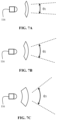
- FIG. 7 A illustrates a narrow beam angle of an irradiation device using a first lens, in accordance with another embodiment of the present invention
- FIG. 7 B illustrates a flood beam angle of the irradiation device using a second lens of the irradiation device of FIG. 7 A ;
- FIG. 7 C illustrates a wide beam angle of the irradiation device using a third lens of the irradiation device of FIG. 7 A .
- the present invention provides an irradiation device that is capable of emitting electromagnetic radiation at variable beam angles.
- terms like “light”, “radiation”, “irradiation”, “emission” and “illumination”, etc. refer to electromagnetic radiation in frequency ranges varying from the Ultraviolet (UV) frequencies to Infrared (IR) frequencies and wavelength, wherein the range is inclusive of UV and IR frequencies and wavelengths.
- UV radiation can be categorized in several manners depending on respective wavelength ranges, all of which are envisaged to be under the scope of this invention.
- UV radiation can be categorized as, Hydrogen Lyman-a (122-121 nm), Far UV (200-122 nm), Middle UV (300-200 nm), Near UV (400-300 nm).
- the UV radiation may also be categorized as UVA (400-315 nm), UVB (315-280 nm), and UVC (280-100 nm).
- IR radiation may also be categorized into several categories according to respective wavelength ranges which are again envisaged to be within the scope of this invention.
- a commonly used subdivision scheme for IR radiation includes Near IR (0.75-1.4 ⁇ m), Short-Wavelength IR (1.4-3 ⁇ m), Mid-Wavelength IR (3-8 ⁇ m), Long-Wavelength IR (8-15 ⁇ m) and Far IR (15-1000 ⁇ m).
- the irradiation device of the present invention has been envisaged to be embodied in a form factor of a linear Light Emitting Diode (LED) tube so that it can easily be mounted on readily available electrical fixtures and hence the invention does not necessitate any significant process architecture redesign and provide savings on capital investment.
- LED Light Emitting Diode
- several lenses with varying optical characteristics, such as thickness, focal length, concavity, color coating, and polarization, etc. may be provided along, on inner or outer surfaces of what would be a longitudinal shell of the linear LED tube.
- a radiation source may be provided within the longitudinal portion and variation in beam angles and other characteristics of the emitted electromagnetic radiation may be achieved through the relative rotation between the lenses and the radiation source.
- the radiation source in that regard may be monochromatic or may be capable of emitting radiation in a broad range of frequencies and wavelengths.
- the radiation source may include Light Emitting Diodes (LEDs) for the invention, owing to power efficiencies achieved by the LEDs and rapid advancements in the field of LED technology which have made them available for several applications including indicator LEDs, lighting devices, treatment and automotive applications such as headlamps.
- the LEDs in that regard may be mounted on a Printed Circuit Board (PCB) through Surface Mounting Technology (SMT).
- PCB Printed Circuit Board
- SMT Surface Mounting Technology
- SMT permits the creation of smaller PCB designs by allowing components to be placed closer together on the board that makes the device more lightweight and compact.
- the SMT process is faster to set up for production and requires less manufacturing cost than its counterpart, through-hole technology because it does not require the circuit board to be drilled for assembly.
- the present irradiation device is envisaged to be applicable for both non-invasive therapeutic applications and spatial lighting purposes.
- certain design variations such as a type, material or make of the radiation source, and emission characteristics of the emitted electromagnetic radiation may need to be altered to suit specific needs of an application, without departing from the scope of the invention.
- FIG. 1 A illustrates an exploded view of an irradiation device 100 capable of emitting electromagnetic radiation at variable beam angles, in accordance with an embodiment of the present invention.
- the irradiation device 100 as illustrated in FIG. 1 A has been embodied in the form of a linear LED tube.
- the irradiation device 100 as shown in FIG. 1 A includes a housing assembly 102 through which the light is emitted towards the surroundings.
- the housing assembly 102 includes a longitudinal shell 104 that may be made of glass, plastic, polycarbonate material, etc. It is further envisaged that the longitudinal shell 104 is at least partially transparent to allow electromagnetic radiation to pass through.
- the longitudinal shell 104 may also be made of nano plastic material that offers improved mechanical properties like hardness, stiffness, etc.
- the nano plastic material makes the longitudinal shell 104 highly resilient to damage, even when compared to the already robust polycarbonate and aluminum materials used in most of the lamps with a longitudinal or a linear form factor.
- the longitudinal shell 104 may also be constructed from bio-polymers or recycled conventional polymers for sustainability purposes.
- the longitudinal shell 104 for this invention is envisaged to be a hollow body with a cross-section that may be circular, polygonal or elliptical, etc. depending upon specific applications.
- the longitudinal shell 104 includes a first end 106 and a second end 108 at extremities of the longitudinal shell 104 .
- the housing assembly 102 further includes a first end cap assembly 110 provided at the first end 106 .
- a second end cap assembly 112 provided at the second end 108 .
- the irradiation device 100 further includes a radiation source 116 provided within the longitudinal shell 104 .
- the radiation source 116 may be configured to emit electromagnetic radiation in Ultra-Violet (UV), visible light, and Infrared (IR) wavelengths bands of the electromagnetic spectrum, depending upon specific application of the irradiation device 100 .
- the radiation source 116 may include a plurality of Light Emitting Diodes (LEDs).
- the LEDs are characterized by their superior power efficiencies, smaller sizes, rapidity in switching, physical robustness, and longevity when compared with incandescent or fluorescent lamps.
- the one or more LEDs may be through-hole type LEDs (generally used to produce electromagnetic radiations of red, green, yellow, blue and white colors), Surface Mount LEDs, Bi-color LEDs, Pulse Width Modulated RGB (Red-Green-Blue) LEDs, and high power LEDs, etc.
- Materials used in the one or more LEDs may vary from one embodiment to another depending upon the frequency of radiation required. Different frequencies can be obtained from LEDs made from pure or doped semiconductor materials. Commonly used semiconductor materials include nitrides of Silicon, Gallium, Aluminum, and Boron, and Zinc Selenide, etc. in pure form or doped with elements such as Aluminum and Indium, etc. For example, red and amber colors are produced from Aluminum Indium Gallium Phosphide (AlGaInP) based compositions, while blue, green, and cyan use Indium Gallium Nitride based compositions. White light may be produced by mixing red, green, and blue lights in equal proportions, while varying proportions may be used for generating a wider color gamut.
- AlGaInP Aluminum Indium Gallium Phosphide
- blue, green, and cyan use Indium Gallium Nitride based compositions.
- White light may be produced by mixing red, green, and blue lights in equal proportions, while varying proportions may be used for generating a wider
- White and other colored lightings may also be produced using phosphor coatings such as Yttrium Aluminum Garnet (YAG) in combination with a blue LED to generate white light and Magnesium doped potassium fluorosilicate in combination with blue LED to generate red light. Additionally, near Ultra Violet (UV) LEDs may be combined with europium based phosphors to generate red and blue lights and copper and zinc doped zinc sulfide-based phosphor to generate green light.
- YAG Yttrium Aluminum Garnet
- UV LEDs near Ultra Violet (UV) LEDs may be combined with europium based phosphors to generate red and blue lights and copper and zinc doped zinc sulfide-based phosphor to generate green light.
- one or more LEDs may also be provided on an Organic LED (OLED) based flexible panel or an inorganic LED-based flexible panel.
- OLED panels may be generated by depositing organic semiconducting materials over Thin Film Transistor (TFT) based substrates.
- TFT Thin Film Transistor
- discussion on generation of OLED panels can be found in Bardsley , J. N (2004), “ International OLED Technology Roadmap”, IEEE Journal of Selected Topics in Quantum Electronics , Vol. 10, No. 1, that is included herein in its entirety, by reference.
- An exemplary description of flexible inorganic light-emitting diode strips can be found in granted U.S. Pat. No. 7,476,557 B2, titled “Roll-to-roll fabricated light sheet and encapsulated semiconductor circuit devices”, which is included herein in its entirety, by reference.
- the one or more LEDs may also be micro-LEDs described through U.S. Pat. Nos. 8,809,126 B2, 8,846,457 B2, 8,852,467 B2, 8,415,879 B2, 8,877,101 B2, 9,018,833 B2 and their respective family members, assigned to NthDegree Technologies Worldwide Inc ., which are included herein by reference, in their entirety.
- the one or more LEDs in that regard, may be provided as a printable composition of the micro-LEDs, printed on a substrate.
- the irradiation device 100 includes a rotate and lock mechanism 118 adapted to allow rotational adjustment of the longitudinal shell 104 .
- the rotate and lock mechanism 118 is constituted by a spring element 109 and a contact element 111 attached with the first end 106 in the first end cap assembly 110 .
- the contact element 111 is hollow on one side to receive the longitudinal shell 104 within and solid on another side that is in contact with the spring element 109 .
- a pair 117 of meshing sets of teeth has been provided within the housing assembly 102 , on the opposite side of the spring element 109 .
- a first set of teeth 113 of the pair 117 is provided at the second end 108 of the longitudinal shell 104 and a second set of meshing teeth 115 of the pair 117 , is provided at an inner surface of the second end cap assembly 112 .
- the pair 117 of meshing sets of teeth may be designed to incorporate several least counts of angular adjustment of the longitudinal shell 104 .
- an angular shift of 10 degrees of the longitudinal shell 104 may be effectuated.
- the least count, in this case, would, therefore, be 10 degrees.
- the rotate and lock mechanism 118 may be designed for different least counts such as 10, 20, 25, 30, 45, or 60 degrees, etc., depending upon specific applications.
- FIG. 1 B illustrates a sectional view of the irradiation device 100 of FIG. 1 A , with the rotate and lock mechanism 118 in an engaged position.
- the spring element 109 In the engaged position, the spring element 109 is in the least compressed state thereby pushing the contact element 111 and therefore the longitudinal shell 104 against the second end cap assembly 112 .
- the first set of meshing teeth 113 and the second set of meshing teeth 115 of the pair 117 are in a meshed state with respect to each other, thereby arresting any rotation of the longitudinal shell 104 .
- the irradiation device 100 is further illustrated to include a plurality of lenses 114 ( 114 a and 114 b ) provided along with the longitudinal shell 104 .
- the plurality of lenses 114 may be provided on one or more of an inner surface (such as lenses 114 a and 114 b ) and an outer surface of the longitudinal shell 104 . Also, anyone or more of the plurality of lenses 114 may be attached to the longitudinal shell 104 , preferably on the outer surface, using an attachment means, depending upon the application of the irradiation device 100 .
- each one of the plurality of lenses 114 has a distinct set of optical characteristics from other lenses of the plurality of lenses 114 .
- the plurality of lenses 114 may have distinct shapes such as round, square and hexagonal, etc., opacity, additives, materials, coatings, and other such factors that may affect the radiation being received from the irradiation device 100 .
- the plurality of lenses 114 may be selected based on factors such as a particular beam angle, intensity, spot size in terms of length of the diameter of the spot created, distance of the spot from the irradiation device 100 , the type of the radiation source 116 , and other factors.
- the plurality of lenses 114 may be suited to the specific construction of the radiation source 116 that might be used, for example for a single LED or an entire array of several LEDs arranged in a predetermined pattern, such as a one-dimensional strip or a two-dimensional board, where the radiation source 116 includes a plurality of LEDs. It is to be noted here that the one or more LEDs may or may not be available with pre-installed primary optics.
- the plurality of lenses 114 may include one or more concave, convex, Fresnel, or compound lenses.
- the plurality of lenses 114 in several embodiments may also include Total Internal Reflection (TIR) lenses that are mostly injection molded from a polymer material and utilize a refractive lens inside a reflector.
- TIR Total Internal Reflection
- FIG. 1 C illustrates a sectional view of the irradiation device 100 of FIG. 1 A , with the rotate and lock mechanism 118 in a disengaged position.
- the spring element 109 In the disengaged position, the spring element 109 is in a maximum compressed state thereby releasing the contact element 111 and therefore the longitudinal shell 104 from the second end cap assembly 112 .
- the first set of meshing teeth 113 and the second set of meshing teeth 115 of the pair 117 are unmeshed with respect to each other, thereby allowing rotational adjustment of the longitudinal shell 104 .
- the longitudinal shell 104 may then be rotated to facilitate alignment of a predetermined lens of the plurality of lenses 114 with the radiation source 116 to modify emission characteristics, including the beam angle, of the electromagnetic radiation emitted by the irradiation device 100 .
- FIG. 2 illustrates a visual representation of the rotational adjustment of the longitudinal shell 104 of the irradiation device 100 of FIG. 1 A .
- an operator 200 may be able to hold the longitudinal shell 104 and push it backward towards the first end cap assembly 110 , thereby compressing the spring element 109 . This allows the pair 117 of the first set of meshing teeth 113 and the second set of meshing teeth 115 , to disengage, in the second end cap assembly 112 , thereby allowing rotational adjustment of the longitudinal shell 104 .
- special contact-based electrically conducting terminals may be provided between the first 113 and the respective second 115 sets of meshing teeth, to ensure that power supply to the radiation source 116 is only available when the pair 117 is in meshed state and the power supply to the radiation source 116 may be cut-off when the first 113 and the respective second 115 sets of meshing teeth are no longer in contact with each other. This is both a safety measure to prevent the operator 200 from accidental exposure to potentially harmful radiation, of the operator 200 during angular adjustment of the longitudinal shell 104 and to save electrical power as the radiation source 116 need not necessarily be activated during the angular adjustment of the longitudinal shell 104 .
- FIG. 3 illustrates a sectional view of the irradiation device 100 capable of emitting electromagnetic radiation at variable beam angles, in accordance with another embodiment of the present invention.
- the irradiation device 100 in this embodiment includes three lenses 114 ( 114 c , 114 d , and 114 e ), as against two ( 114 a , 114 b ) depicted in the previous embodiment of FIG. 1 A .
- the invention is not limited to a specific number for the plurality of lenses 114 or specific construction of the plurality of lenses 114 .
- FIG. 4 A illustrates a sectional view of the irradiation device 100 of FIG. 3 , sectioned along a plane A-A.
- the rotate and lock mechanism 118 is constituted by meshing gear teeth sets 302 and 304 , wherein a first set of gear teeth 302 has been provided along an inner surface of the first end 106 of the longitudinal shell 104 . Further, a second set of gear teeth 304 has been provided through a gear located within the first end cap assembly 110 .
- the rotate and lock mechanism 118 is adapted to cause rotation of the longitudinal shell 104 when actuated by an actuator.
- the radiation source 116 is capable of rotating within the longitudinal shell 104 .
- FIG. 4 B illustrates a sectional view of the irradiation device 100 of FIG. 3 , sectioned along a plane B-B.
- the radiation source 116 is also capable of rotating within the longitudinal shell 104 , through meshing gear teeth sets 412 and 414 of a second rotate and lock mechanism 410 .
- the second rotate and lock mechanism 410 has been provided within the second end cap assembly 112 .
- the locations of the rotate and lock mechanism 118 and the second rotate and lock mechanism 410 are interchangeable or both may be located at any one end of the longitudinal shell 104 .
- FIG. 5 illustrates an exploded view of the irradiation device 100 of FIG. 3 .
- the rotate and lock mechanism 118 includes a first electrical actuator 510 adapted to cause the rotation of the second set of gear teeth 204 .
- the first electrical actuator 510 may be an AC motor, a DC motor, a servo motor, a stepper motor, or the like.
- a second electrical actuator 520 is adapted to cause the rotation of the radiation source 116 through the rotation of the gear teeth set 414 of the second rotate and lock mechanism 410 .
- the second electrical actuator may also be an AC motor, a DC motor, a servo motor, a stepper motor, or the like.
- the longitudinal shell 104 may be allowed to rotate for alignment of the radiation source 116 with any predetermined lens of the plurality of lenses 114 . Following the alignment of the radiation source 116 with any one of the plurality of lenses 114 , the longitudinal shell 104 may be desired to be locked again. Additionally, even in scenarios where the longitudinal shell 104 alone is being rotated in place of the radiation source 116 , it would be advantageous to lock the rotation of the longitudinal shell 104 , once the adjustment has been performed, to ensure any accidental movement or misalignment of the radiation source 116 with any one of the plurality of lenses 114 .
- the first electrical actuator 510 may be a DC motor with a self-locking shaft that is locked in its position until the current is supplied to the first electrical actuator 510 .
- the self-locking shaft of the first electrical actuator 510 would be capable of arresting the rotation of the longitudinal shell 104 .
- the second electrical actuator 520 may also be a DC motor with a self-locking shaft that is locked in its position until the current is supplied to the second electrical actuator 520 .
- the self-locking shaft of the second electrical actuator 520 would then be capable of arresting the rotation of the radiation source 116 .
- the self-locking shafts of the first electrical actuator 510 and the second electrical actuator 520 may include self-locking arrangements such as worm and worm shaft type, solenoid brake type, or any other self-locking shaft arrangements known in the art.
- FIG. 6 illustrates a cross-sectional view of the irradiation device 100 of FIG. 3 .
- the plurality of lenses 114 such as concave, Fresnel, and convex lens are provided along with the longitudinal shell 104 of the irradiation device 100 as shown in FIG. 6 .
- the concave lens 114 c and the convex lens 114 e have been provided along the inner surface of the longitudinal shell 104
- the Fresnel lens 114 d has been provided along the outer surface of the longitudinal shell 104 .
- the invention is not limited to the aforementioned concave, convex, and Fresnel lens apart from them, different types of lenses having distinct focal length can be used for the invention.
- a user may rotate the longitudinal shell 104 of the irradiation device 100 by actuating, either remotely or through a contact-based switch, the first electrical actuator 510 . Due to the rotational movement of longitudinal shell 104 , the plurality of lenses 114 provided along with the longitudinal shell 104 also rotate, resulting in the beam angle adjustment of the radiation emitted by the radiation source 116 , when one of the plurality of lenses 114 aligns with the radiation source 116 . Alternately, the user may actuate the second electrical actuator 520 , thus causing the rotation of the radiation source 116 to align with a predetermined lens of the plurality of lenses 114 . In such a scenario, not only variations in beam angles would be achieved, but the beam direction will also change with the rotation of the radiation source 116 .
- the radiation source 116 may be inactive during the adjustment of the beam angle and other optical characteristics, to ensure power savings and undesirable light glare problems caused to an operator.
- motion sensors may be installed on the longitudinal shell 104 and the radiation source 116 , that may detect the rotation of the longitudinal shell 104 and the radiation source 116 and cause the deactivation of the radiation source 116 .
- the deactivation of the radiation source 116 may also be facilitated through an electromechanical or solid-state switch that may be operated either automatically based on motion sensor feedback or manually by the operator.
- the irradiation device 100 has been designed to operate both as a therapeutic device for non-invasive radiation treatment for conditions such as skin acne and aging, muscle spasms and inflammations and in some cases benign or malignant lesions and as an artificial lighting device in spatial lighting applications.
- the key factors that may affect the efficacy of the treatment include wavelengths, the power density of irradiation, time of exposure, distance of the affected area from the irradiation device 100 and mode of operation of the radiation source 116 .
- the radiation source 116 may be configured to operate in pulsed or continuous mode.
- I mA input current of (I mA) and applied voltage of (V Volts)
- P I V ⁇ I mW (1)
- the area (A) being effectively irradiated by the irradiation device 100 , with a beam angle ( ⁇ ), for a subject standing at a distance (d cm) would be given by equation (3).
- K is the correction factor for accounting for the entire beam spread that will be greater than the beam angle.
- the correction factor ‘K’ may be empirically determined during the calibration of the irradiation device 100 . Therefore, the dosage (D) and total irradiant energy (E a ) being absorbed by the subject, receiving treatment for a time period (T seconds) would be given by equations (5) and (6), respectively.
- D P d ⁇ T mJ/cm 2 (5)
- E a D ⁇ A mJ (6)
- the treatment received by the subject individual may be varied by varying parameters such as the input current, applied voltage, beam angle of the irradiation, distance of the subject from the irradiation device and treatment time, etc.
- an effective dose for wound healing is 90 J/cm 2 .
- the value of input current, applied voltage, and construction of the radiation source 116 (for example be it laser or LEDs) will also be dictated by other factors such as type of condition (for example, acne, deep wounds, and lesions, etc.) and type of radiation output (for example, blue light, UV radiation, red light or IR radiation) suited for that condition.
- the irradiation device 100 would most likely be emitting radiation in form of the wide spectrum visible light and therefore the efficacy of the irradiation device 100 would be evaluated differently than as described through equations (1) to (6).
- the key characteristics in the application of the irradiation device 100 include angular span, beam angle, apex angle, a distance of a surface being illuminated from the irradiation device 100 , luminous intensity and luminous flux being emitted.
- apex angle ( ⁇ ) For a surface at a distance (d) cm from the irradiation device 100 , emitting visible light at a beam angle ( ⁇ ), the apex angle ( ⁇ ) would be determined from equation (7) and angular span ( ⁇ ) would be determined from equation (8).
- the illumination of the surface also known as the lux value at the surface may be determined by dividing the luminous flux (L) with the area (A) determined from equation (3).
- the lux value (1) is thus given by equation (10).
- the lux value (1) is generally the value that is measured by light meters. Also, it can be seen from equation (10) and (3) that the lux value, therefore, depends on the beam angle and the distance of the surface from the irradiation device 100 .
- FIG. 7 A illustrates a narrow beam angle ( ⁇ 1 ) of an irradiation device 100 using a first lens having a relatively long focal length, in accordance with another embodiment of the present invention.
- the first lens used in this embodiment when aligned with the radiation source 116 emits light at the narrow beam angle (5 to 20 degree).
- FIG. 7 B illustrates a flood beam angle ( ⁇ 2 ) of the irradiation device 100 using a second lens having a relatively shorter focal length when compared with the first lens.
- the second lens used in this embodiment when aligned with the radiation source 116 emits light at the flood beam angle (20 to 50 degrees).
- FIG. 7 C illustrates a wide beam angle ( ⁇ 3 ) of the irradiation device 100 using a third lens having an even shorter focal length when compared with the second lens.
- the third lens used in this embodiment when aligned with the radiation source 116 emits light at a broader beam angle (more than 50 degrees).
- the construction of the irradiation device as described above is not only economical from a manufacturing point of view, but the embodiment of the irradiation device in form of a linear LED tube would allow the irradiation device to be mounted in readily available electrical fixtures. This would allow both savings in time and effort that would have been required in the redesign of the electrical fixtures but also savings in capital investment that would have been incurred in the purchase and installation of such fixtures.
- the beam angle ( ⁇ ), angular span ( ⁇ ) and luminous flux (L) would be determined as below:
- the illumination of the surface or lux value (1) would be determined as follows:
Landscapes
- Health & Medical Sciences (AREA)
- Engineering & Computer Science (AREA)
- Biomedical Technology (AREA)
- Pathology (AREA)
- Nuclear Medicine, Radiotherapy & Molecular Imaging (AREA)
- Radiology & Medical Imaging (AREA)
- Life Sciences & Earth Sciences (AREA)
- Animal Behavior & Ethology (AREA)
- General Health & Medical Sciences (AREA)
- Public Health (AREA)
- Veterinary Medicine (AREA)
- Non-Portable Lighting Devices Or Systems Thereof (AREA)
- Radiation-Therapy Devices (AREA)
Abstract
Description
P I =V×I mW (1)
P o η×P I mW (2)
D=P d ×T mJ/cm2 (5)
E a =D×A mJ (6)
L=C×σ lumens (9)
Claims (6)
Priority Applications (1)
| Application Number | Priority Date | Filing Date | Title |
|---|---|---|---|
| US16/875,991 US11602640B2 (en) | 2020-05-16 | 2020-05-16 | Irradiation device with adjustable beam angle |
Applications Claiming Priority (1)
| Application Number | Priority Date | Filing Date | Title |
|---|---|---|---|
| US16/875,991 US11602640B2 (en) | 2020-05-16 | 2020-05-16 | Irradiation device with adjustable beam angle |
Publications (2)
| Publication Number | Publication Date |
|---|---|
| US20210353953A1 US20210353953A1 (en) | 2021-11-18 |
| US11602640B2 true US11602640B2 (en) | 2023-03-14 |
Family
ID=78513849
Family Applications (1)
| Application Number | Title | Priority Date | Filing Date |
|---|---|---|---|
| US16/875,991 Active 2040-06-18 US11602640B2 (en) | 2020-05-16 | 2020-05-16 | Irradiation device with adjustable beam angle |
Country Status (1)
| Country | Link |
|---|---|
| US (1) | US11602640B2 (en) |
Families Citing this family (2)
| Publication number | Priority date | Publication date | Assignee | Title |
|---|---|---|---|---|
| US11457204B1 (en) | 2020-11-06 | 2022-09-27 | Waymo Llc | Localized window contaminant detection |
| CN117042842A (en) * | 2022-01-24 | 2023-11-10 | 哈维尔斯印度有限公司 | Lighting fixtures used to produce vitamin D-safe UV radiation |
Citations (14)
| Publication number | Priority date | Publication date | Assignee | Title |
|---|---|---|---|---|
| US20020161418A1 (en) * | 2001-03-08 | 2002-10-31 | Wilkens Jan Hennrik | Irradiation device |
| US20050105690A1 (en) * | 2003-11-19 | 2005-05-19 | Stanley Pau | Focusable and steerable micro-miniature x-ray apparatus |
| CN202791418U (en) * | 2012-07-13 | 2013-03-13 | 中山市尔全照明有限公司 | An LED lamp with adjustable light angle |
| US8415879B2 (en) | 2007-05-31 | 2013-04-09 | Nthdegree Technologies Worldwide Inc | Diode for a printable composition |
| US8809126B2 (en) | 2007-05-31 | 2014-08-19 | Nthdegree Technologies Worldwide Inc | Printable composition of a liquid or gel suspension of diodes |
| US8846457B2 (en) | 2007-05-31 | 2014-09-30 | Nthdegree Technologies Worldwide Inc | Printable composition of a liquid or gel suspension of diodes |
| US8852467B2 (en) | 2007-05-31 | 2014-10-07 | Nthdegree Technologies Worldwide Inc | Method of manufacturing a printable composition of a liquid or gel suspension of diodes |
| US8877101B2 (en) | 2007-05-31 | 2014-11-04 | Nthdegree Technologies Worldwide Inc | Method of manufacturing a light emitting, power generating or other electronic apparatus |
| US9018833B2 (en) | 2007-05-31 | 2015-04-28 | Nthdegree Technologies Worldwide Inc | Apparatus with light emitting or absorbing diodes |
| CN204805995U (en) * | 2015-05-07 | 2015-11-25 | 海宁市明帅照明科技有限公司 | LED tube |
| US20160129279A1 (en) * | 2014-07-09 | 2016-05-12 | Akari Systems, Inc. | Wearable therapeutic light source |
| US20160367833A1 (en) * | 2015-06-22 | 2016-12-22 | Quantum Dynamics, LLC | Device for Providing Body Temperature Regulation and/or Therapeutic Light Directed to Vasculature |
| CN207065451U (en) | 2017-07-26 | 2018-03-02 | 漳州立达信光电子科技有限公司 | A kind of LED light tube |
| US20200315907A1 (en) * | 2019-04-07 | 2020-10-08 | Light tree | Phototherapy Body Roller |
-
2020
- 2020-05-16 US US16/875,991 patent/US11602640B2/en active Active
Patent Citations (14)
| Publication number | Priority date | Publication date | Assignee | Title |
|---|---|---|---|---|
| US20020161418A1 (en) * | 2001-03-08 | 2002-10-31 | Wilkens Jan Hennrik | Irradiation device |
| US20050105690A1 (en) * | 2003-11-19 | 2005-05-19 | Stanley Pau | Focusable and steerable micro-miniature x-ray apparatus |
| US8852467B2 (en) | 2007-05-31 | 2014-10-07 | Nthdegree Technologies Worldwide Inc | Method of manufacturing a printable composition of a liquid or gel suspension of diodes |
| US8415879B2 (en) | 2007-05-31 | 2013-04-09 | Nthdegree Technologies Worldwide Inc | Diode for a printable composition |
| US8809126B2 (en) | 2007-05-31 | 2014-08-19 | Nthdegree Technologies Worldwide Inc | Printable composition of a liquid or gel suspension of diodes |
| US8846457B2 (en) | 2007-05-31 | 2014-09-30 | Nthdegree Technologies Worldwide Inc | Printable composition of a liquid or gel suspension of diodes |
| US8877101B2 (en) | 2007-05-31 | 2014-11-04 | Nthdegree Technologies Worldwide Inc | Method of manufacturing a light emitting, power generating or other electronic apparatus |
| US9018833B2 (en) | 2007-05-31 | 2015-04-28 | Nthdegree Technologies Worldwide Inc | Apparatus with light emitting or absorbing diodes |
| CN202791418U (en) * | 2012-07-13 | 2013-03-13 | 中山市尔全照明有限公司 | An LED lamp with adjustable light angle |
| US20160129279A1 (en) * | 2014-07-09 | 2016-05-12 | Akari Systems, Inc. | Wearable therapeutic light source |
| CN204805995U (en) * | 2015-05-07 | 2015-11-25 | 海宁市明帅照明科技有限公司 | LED tube |
| US20160367833A1 (en) * | 2015-06-22 | 2016-12-22 | Quantum Dynamics, LLC | Device for Providing Body Temperature Regulation and/or Therapeutic Light Directed to Vasculature |
| CN207065451U (en) | 2017-07-26 | 2018-03-02 | 漳州立达信光电子科技有限公司 | A kind of LED light tube |
| US20200315907A1 (en) * | 2019-04-07 | 2020-10-08 | Light tree | Phototherapy Body Roller |
Non-Patent Citations (1)
| Title |
|---|
| Egger, J. Use of Fresnel lenses in optical systems: some advantages and limitations. Proc. SPIE 0193, Optical Systems in Engineering I, (Nov. 29, 1979); https://doi.org/10.1117/12.957873 (Year: 1979). * |
Also Published As
| Publication number | Publication date |
|---|---|
| US20210353953A1 (en) | 2021-11-18 |
Similar Documents
| Publication | Publication Date | Title |
|---|---|---|
| US11193653B1 (en) | Irradiation device with a deformable optic | |
| JP6396609B2 (en) | Lighting assembly that emits part of UV light | |
| ES2629579T3 (en) | A light emission module, a lamp, a luminaire and a method of lighting an object | |
| US9551468B2 (en) | Inverse visible spectrum light and broad spectrum light source for enhanced vision | |
| US8523924B2 (en) | Colored and white light generating lighting device | |
| EP2898548B1 (en) | A light emitting assembly, a lamp and a luminaire | |
| US20080198597A1 (en) | Illumination Device | |
| US20110210273A1 (en) | Uv lamp | |
| JP2008235439A (en) | White light source device | |
| US10775635B2 (en) | Color mixing in laser-based light source | |
| US11602640B2 (en) | Irradiation device with adjustable beam angle | |
| US10344950B2 (en) | Light emitting arrangement with controlled spectral properties and angular distribution | |
| EP1639867A1 (en) | Led operation light | |
| KR20130104577A (en) | Lens and bulb type light emitting device lamp employing the same | |
| BR102015026594A2 (en) | dome map lamp with photoluminescent color change | |
| WO2009083853A1 (en) | Lighting system | |
| US11247066B2 (en) | Irradiation device | |
| US11519562B2 (en) | LED filament arrangement | |
| US20200063924A1 (en) | Optical device augmenting the emission of electro-luminescent light sources with help of a dichroic zno nanorod comprising filter | |
| WO2013054226A1 (en) | Light-emitting arrangement | |
| US20100207522A1 (en) | Lamp | |
| WO2022152553A1 (en) | Lighting arrangement for illumination and disinfection lighting | |
| CN121206419A (en) | lighting fixtures | |
| KR20240100161A (en) | UV light emitting unit with reflector and sterilization lighting including the same | |
| CN118302632A (en) | Light guide lamp |
Legal Events
| Date | Code | Title | Description |
|---|---|---|---|
| FEPP | Fee payment procedure |
Free format text: ENTITY STATUS SET TO UNDISCOUNTED (ORIGINAL EVENT CODE: BIG.); ENTITY STATUS OF PATENT OWNER: SMALL ENTITY |
|
| AS | Assignment |
Owner name: LIGHT TREE VENTURES HOLDING B. V., NETHERLANDS Free format text: ASSIGNMENT OF ASSIGNORS INTEREST;ASSIGNOR:DIJKSTRA, ALAIN;REEL/FRAME:052706/0806 Effective date: 20200520 |
|
| FEPP | Fee payment procedure |
Free format text: ENTITY STATUS SET TO SMALL (ORIGINAL EVENT CODE: SMAL); ENTITY STATUS OF PATENT OWNER: SMALL ENTITY |
|
| STPP | Information on status: patent application and granting procedure in general |
Free format text: RESPONSE TO NON-FINAL OFFICE ACTION ENTERED AND FORWARDED TO EXAMINER |
|
| STPP | Information on status: patent application and granting procedure in general |
Free format text: NON FINAL ACTION MAILED |
|
| STPP | Information on status: patent application and granting procedure in general |
Free format text: RESPONSE TO NON-FINAL OFFICE ACTION ENTERED AND FORWARDED TO EXAMINER |
|
| STPP | Information on status: patent application and granting procedure in general |
Free format text: FINAL REJECTION MAILED |
|
| STPP | Information on status: patent application and granting procedure in general |
Free format text: RESPONSE AFTER FINAL ACTION FORWARDED TO EXAMINER |
|
| STPP | Information on status: patent application and granting procedure in general |
Free format text: ADVISORY ACTION MAILED |
|
| STPP | Information on status: patent application and granting procedure in general |
Free format text: DOCKETED NEW CASE - READY FOR EXAMINATION |
|
| STPP | Information on status: patent application and granting procedure in general |
Free format text: NOTICE OF ALLOWANCE MAILED -- APPLICATION RECEIVED IN OFFICE OF PUBLICATIONS |
|
| STPP | Information on status: patent application and granting procedure in general |
Free format text: PUBLICATIONS -- ISSUE FEE PAYMENT RECEIVED |
|
| STPP | Information on status: patent application and granting procedure in general |
Free format text: PUBLICATIONS -- ISSUE FEE PAYMENT VERIFIED |
|
| STCF | Information on status: patent grant |
Free format text: PATENTED CASE |