US11596368B2 - Breast compression paddles utilizing pivoting foam elements - Google Patents
Breast compression paddles utilizing pivoting foam elements Download PDFInfo
- Publication number
- US11596368B2 US11596368B2 US16/981,943 US201916981943A US11596368B2 US 11596368 B2 US11596368 B2 US 11596368B2 US 201916981943 A US201916981943 A US 201916981943A US 11596368 B2 US11596368 B2 US 11596368B2
- Authority
- US
- United States
- Prior art keywords
- foam
- breast
- compression
- subsidiary
- main
- Prior art date
- Legal status (The legal status is an assumption and is not a legal conclusion. Google has not performed a legal analysis and makes no representation as to the accuracy of the status listed.)
- Active, expires
Links
Images




Classifications
-
- A—HUMAN NECESSITIES
- A61—MEDICAL OR VETERINARY SCIENCE; HYGIENE
- A61B—DIAGNOSIS; SURGERY; IDENTIFICATION
- A61B6/00—Apparatus or devices for radiation diagnosis; Apparatus or devices for radiation diagnosis combined with radiation therapy equipment
- A61B6/04—Positioning of patients; Tiltable beds or the like
- A61B6/0407—Supports, e.g. tables or beds, for the body or parts of the body
- A61B6/0414—Supports, e.g. tables or beds, for the body or parts of the body with compression means
-
- A—HUMAN NECESSITIES
- A61—MEDICAL OR VETERINARY SCIENCE; HYGIENE
- A61B—DIAGNOSIS; SURGERY; IDENTIFICATION
- A61B6/00—Apparatus or devices for radiation diagnosis; Apparatus or devices for radiation diagnosis combined with radiation therapy equipment
- A61B6/04—Positioning of patients; Tiltable beds or the like
- A61B6/0407—Supports, e.g. tables or beds, for the body or parts of the body
- A61B6/0435—Supports, e.g. tables or beds, for the body or parts of the body with means for imaging suspended breasts
-
- A—HUMAN NECESSITIES
- A61—MEDICAL OR VETERINARY SCIENCE; HYGIENE
- A61B—DIAGNOSIS; SURGERY; IDENTIFICATION
- A61B6/00—Apparatus or devices for radiation diagnosis; Apparatus or devices for radiation diagnosis combined with radiation therapy equipment
- A61B6/48—Diagnostic techniques
- A61B6/488—Diagnostic techniques involving pre-scan acquisition
-
- A—HUMAN NECESSITIES
- A61—MEDICAL OR VETERINARY SCIENCE; HYGIENE
- A61B—DIAGNOSIS; SURGERY; IDENTIFICATION
- A61B6/00—Apparatus or devices for radiation diagnosis; Apparatus or devices for radiation diagnosis combined with radiation therapy equipment
- A61B6/50—Apparatus or devices for radiation diagnosis; Apparatus or devices for radiation diagnosis combined with radiation therapy equipment specially adapted for specific body parts; specially adapted for specific clinical applications
- A61B6/502—Apparatus or devices for radiation diagnosis; Apparatus or devices for radiation diagnosis combined with radiation therapy equipment specially adapted for specific body parts; specially adapted for specific clinical applications for diagnosis of breast, i.e. mammography
-
- A—HUMAN NECESSITIES
- A61—MEDICAL OR VETERINARY SCIENCE; HYGIENE
- A61B—DIAGNOSIS; SURGERY; IDENTIFICATION
- A61B6/00—Apparatus or devices for radiation diagnosis; Apparatus or devices for radiation diagnosis combined with radiation therapy equipment
- A61B6/52—Devices using data or image processing specially adapted for radiation diagnosis
- A61B6/5258—Devices using data or image processing specially adapted for radiation diagnosis involving detection or reduction of artifacts or noise
-
- A—HUMAN NECESSITIES
- A61—MEDICAL OR VETERINARY SCIENCE; HYGIENE
- A61B—DIAGNOSIS; SURGERY; IDENTIFICATION
- A61B6/00—Apparatus or devices for radiation diagnosis; Apparatus or devices for radiation diagnosis combined with radiation therapy equipment
- A61B6/54—Control of apparatus or devices for radiation diagnosis
- A61B6/542—Control of apparatus or devices for radiation diagnosis involving control of exposure
-
- A—HUMAN NECESSITIES
- A61—MEDICAL OR VETERINARY SCIENCE; HYGIENE
- A61B—DIAGNOSIS; SURGERY; IDENTIFICATION
- A61B6/00—Apparatus or devices for radiation diagnosis; Apparatus or devices for radiation diagnosis combined with radiation therapy equipment
- A61B6/54—Control of apparatus or devices for radiation diagnosis
- A61B6/542—Control of apparatus or devices for radiation diagnosis involving control of exposure
- A61B6/544—Control of apparatus or devices for radiation diagnosis involving control of exposure dependent on patient size
-
- A—HUMAN NECESSITIES
- A61—MEDICAL OR VETERINARY SCIENCE; HYGIENE
- A61B—DIAGNOSIS; SURGERY; IDENTIFICATION
- A61B6/00—Apparatus or devices for radiation diagnosis; Apparatus or devices for radiation diagnosis combined with radiation therapy equipment
- A61B6/02—Arrangements for diagnosis sequentially in different planes; Stereoscopic radiation diagnosis
- A61B6/025—Tomosynthesis
-
- A—HUMAN NECESSITIES
- A61—MEDICAL OR VETERINARY SCIENCE; HYGIENE
- A61B—DIAGNOSIS; SURGERY; IDENTIFICATION
- A61B6/00—Apparatus or devices for radiation diagnosis; Apparatus or devices for radiation diagnosis combined with radiation therapy equipment
- A61B6/02—Arrangements for diagnosis sequentially in different planes; Stereoscopic radiation diagnosis
- A61B6/03—Computed tomography [CT]
- A61B6/032—Transmission computed tomography [CT]
Definitions
- Compression during mammography and tomosynthesis imaging serves a number of purposes. For example, it: (1) makes the breast thinner in the direction of x-ray flux and thereby reduces patient radiation exposure from the level required to image the thicker parts of a breast that are not compressed; (2) makes the breast more uniform in thickness in the direction of x-ray flux and thereby facilitates more uniform exposure at the image plane over the entire breast image; (3) immobilizes the breast during the x-ray exposure and thereby reduces image blurring; and (4) brings breast tissues out from the chest wall into the imaging exposure field and thus allows for more tissue imaging. As the breast is being compressed, typically a technologist manipulates the breast to position it appropriately and counter the tendency that compression has of pushing breast tissue toward the chest wall and out of the image field.
- Standard compression methods for mammography and tomosynthesis use a movable, rigid, radiolucent compression paddle.
- the breast is placed on a breast support platform that typically is flat, and the paddle then compresses the breast, usually while a technologist or other health professional is holding the breast in place.
- the technologist may also manipulate the breast to ensure proper tissue coverage in the image receptor's field of view.
- One known challenge in mammography and breast tomosynthesis is the discomfort the patient may feel when the breast is compressed, which must be done with sufficient force to immobilize the breast and spread out the breast tissues for x-ray imaging. Discomfort may potentially cause the patient to move, which negatively impacts image quality. Discomfort may also potentially dissuade patients from getting screened for breast cancer. Another known challenge is to ensure that the imaged field includes the desired amount of breast tissue.
- the technology relates to a breast compression paddle including: a bracket for removably securing the breast compression paddle to an imaging system; a rigid frame secured to the bracket, wherein the rigid frame includes: two side walls, each having a side wall upper edge, wherein each of the two side walls extends from the bracket; and a leading wall having a leading wall upper edge, wherein the leading wall is disposed distal from the bracket, wherein the leading wall spans the two side walls; a substrate movably secured to at least one of the bracket and the rigid frame between a first position and a second position, wherein when in the first position, at least a portion of the substrate is disposed above the upper edges of the two side walls and the upper edge of the leading wall, and wherein when in the second position, the substrate is disposed below the upper edges of the two side walls and the upper edge of the leading wall; and a foam secured to the substrate, and wherein when in the first position, at least a portion of the foam is disposed above the upper edges of the two side walls and
- the substrate is rigid.
- the substrate is movably secured to the bracket at an edge proximate the bracket.
- the breast compression paddle further includes a strut system, wherein the strut system movably secures the substrate to the bracket.
- the edge has at least one of a live hinge and a pivoting hinge.
- the substrate is pivotably connected to the frame proximate a mid-point of the frame and the substrate.
- the frame is pivotably connected to the bracket.
- the bracket has an element configured to be slidably connected to a compression arm of an imaging system.
- at least a portion of the leading wall is curved.
- the substrate is flexible.
- the leading wall includes a vertical portion and a substantially horizontal portion.
- the foam is further secured to the substantially horizontal portion.
- the foam movably connects the substrate to the frame.
- FIG. 1 A is a schematic view of an exemplary imaging system.
- FIG. 1 B is a perspective view of the imaging system of FIG. 1 A .
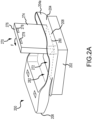
- FIG. 2 A is a perspective view of a compression paddle having a hinged portion of a foam compressive element in accordance with another example.
- FIG. 2 B is a perspective view of a compression paddle having a hinged portion of a foam compressive element in accordance with another example.
- FIGS. 3 A- 3 B depict another example of a compression paddle having a movable foam compressive element, at various positions during compression procedures.
- FIGS. 4 A- 4 C depict another example of a compression paddle having a movable foam compressive element, at various positions during compression procedures.
- FIG. 5 depicts another method of compressing a breast in an imaging system.
- FIG. 1 A is a schematic view of an exemplary imaging system 100 .
- FIG. 1 B is a perspective view of the imaging system 100 .
- the imaging system 100 immobilizes a patient's breast 102 for x-ray imaging (either or both of mammography and tomosynthesis) via a breast compression immobilizer unit 104 that includes a static breast support platform 106 and a moveable compression paddle 108 .
- the breast support platform 106 and the compression paddle 108 each have a compression surface 110 and 112 , respectively, that move towards each other to compress and immobilize the breast 102 .
- the compression surface 110 , 112 is exposed so as to directly contact the breast 102 .
- the platform 106 also houses an image receptor 116 and, optionally, a tilting mechanism 118 , and optionally an anti-scatter grid.
- the immobilizer unit 104 is in a path of an imaging beam 120 emanating from x-ray source 122 , such that the beam 120 impinges on the image receptor 116 .
- the immobilizer unit 104 is supported on a first support arm 124 and the x-ray source 122 is supported on a second support arm 126 .
- support arms 124 and 126 can rotate as a unit about an axis 128 between different imaging orientations such as CC and MLO, so that the system 100 can take a mammogram projection image at each orientation.
- the image receptor 116 remains in place relative to the platform 106 while an image is taken.
- the immobilizer unit 104 releases the breast 102 for movement of arms 124 , 126 to a different imaging orientation.
- the support arm 124 stays in place, with the breast 102 immobilized and remaining in place, while at least the second support arm 126 rotates the x-ray source 122 relative to the immobilizer unit 104 and the compressed breast 102 about the axis 128 .
- the system 100 takes plural tomosynthesis projection images of the breast 102 at respective angles of the beam 120 relative to the breast 102 .
- the image receptor 116 may be tilted relative to the breast support platform 106 and in sync with the rotation of the second support arm 126 .
- the tilting can be through the same angle as the rotation of the x-ray source 122 , but may also be through a different angle selected such that the beam 120 remains substantially in the same position on the image receptor 116 for each of the plural images.
- the tilting can be about an axis 130 , which can but need not be in the image plane of the image receptor 116 .
- the tilting mechanism 118 that is coupled to the image receptor 116 can drive the image receptor 116 in a tilting motion.
- the breast support platform 106 can be horizontal or can be at an angle to the horizontal, e.g., at an orientation similar to that for conventional MLO imaging in mammography.
- the system 100 can be solely a mammography system, a CT system, or solely a tomosynthesis system, or a “combo” system that can perform multiple forms of imaging.
- An example of such a combo system has been offered by the assignee hereof under the trade name Selenia Dimensions.
- the image receptor 116 When the system is operated, the image receptor 116 produces imaging information in response to illumination by the imaging beam 120 , and supplies it to an image processor 132 for processing and generating breast x-ray images.
- a system control and work station unit 138 including software controls the operation of the system and interacts with the operator to receive commands and deliver information including processed-ray images.
- One challenge with the imaging system 100 is how to immobilize and compress the breast 102 for the desired or required imaging.
- a health professional typically an x-ray technologist, generally adjusts the breast 102 within the immobilizer unit 104 while pulling tissue towards imaging area and moving the compression paddle 108 toward the breast support platform 106 to immobilize the breast 102 and keep it in place, with as much of the breast tissue as practicable being between the compression surfaces 110 , 112 .
- the present technology relates to a breast compression system having a foam compressive element and/or other components as described below for use in a breast imaging system.
- a breast compression system having a foam compressive element and/or other components as described below for use in a breast imaging system.
- it is often desirable to immobilize the breast through compression For instance, by compressing the breast, the breast can be made thinner, thus requiring a lower dose of radiation. Further, by immobilizing the breast, image blurring from movement of the breast during imaging is reduced. Other benefits may also be realized by compressing the breast.
- the paddle may also cause discomfort to the patient whose breast is being compressed.
- One reason for discomfort that the patient may feel is that the compression force is non-uniformly distributed throughout the breast. It is often concentrated at the thickest portion of the breast, usually near the chest wall, at or near the lower front edge of the compression paddle and the upper front corner of the breast platform.
- the anterior portion of the breast, such as near the nipple, may receive less compressive force, or no compressive force.
- the paddle may not even contact this portion of the breast.
- CC craniocaudal
- MLO mediolateral oblique
- the compression systems described herein include a foam compressive element that is positioned over a compression surface and contacts the breast during compression.
- foam may additionally or alternatively be disposed on a breast support platform.
- the foam compresses as pressure increases and is generally more comfortable than hard plastic paddles.
- Other features may be utilized to improve technologist visibility of the breast during compressive procedures, as well as to determine the amount of foam compression.
- Appropriate foam materials include super soft urethane foams, such as fire-retardant upholstery foams, that display advantageous performance characteristics. Such materials may be manufactured so as to meet the requirements of ASTM D 3574. Foams having the performance characteristics displayed in Table 1 below have displayed advantageous properties, although other foams having different performance characteristics may also be utilized.
- the foam may be secured to a hard plastic compression paddle substrate with a radiotranslucent adhesive, or may be mechanically secured thereto, for example, with hooks, straps, or other securement structures.
- the foam at least partially conforms in shape to the breast as the paddle is lowered and the foam compresses. This stabilizes and may entirely immobilize (or a portion thereof) the breast for imaging, without requiring the compression pressure typical in breast imaging systems. Additionally, the foam may be placed on the portions of the compression paddle and breast platform that face the chest wall. As the compression paddle is lowered, the foam compresses and takes on a curved shaped that approximates the shape of the breast. However, unlike hard plastic compression paddles, compression forces need not be so high as to completely flatten the breast.
- the foams described herein are utilized to stabilize the breast, not necessarily to effectuate full compression, which is usually performed by flat rigid compression paddles (or by breast compression elements that have a very thin layer of foam disposed thereon.
- full compression which is usually performed by flat rigid compression paddles (or by breast compression elements that have a very thin layer of foam disposed thereon.
- the appearance of the breast would differ (depending on the level of compression of the particular volume of interest), although this appearance may be corrected by image processing algorithms.
- the foam only appears in slices outside of the boundaries of the breast.
- the structures blur out and are not visible.
- the paddles utilizing foams described herein may be used for both mammography and tomosynthesis imaging, although some post-imaging processing may be required to realize all advantages thereof.
- the foam may be rectangular in shape and have outer dimensions sized to match the image receptor size.
- the foam may be uniformly shaped, such as a rectangular prism.
- Other alternative examples may include a non-uniform shape, such as greater thickness at breast contacting portion or greater thickness at edges. Greater thickness at the areas of the foam proximate the edges of the breast may help the foam further conform to and stabilize the breast.
- the foam may include a width between lateral edge surfaces thereof, and a length between a leading edge surface and a trailing edge surface. In one example, the dimensions of the foam may be about 30 cm wide ⁇ 24 cm long.
- the foam may be about 3 inches thick, about 2 inches thick, or about 1 inch thick.
- the desired thickness may be dependent on a number of factors including breast size, breast density, compression paddle size, and so on.
- the foam may include a mounting mechanism for connection to a compression paddle or a breast platform.
- the mounting mechanism may instead be a permanent or semi-permanent adhesive.
- a cover may be disposed on the surfaces of the foam that contact the breast.
- the cover prevents the foam from absorbing sweat or other bodily fluids which may cause damage to the foam or unsanitary conditions.
- the cover may be anti-microbial, cleanable, and fluid-resistant; it is also desirable that the cover is sufficiently pliable so as not to adversely affect the deformation of the foam during compression.
- the cover should also be resistant to cleaning chemicals that may be utilized to sanitize the cover between patients.
- Disposable covers are also contemplated. Such covers may be easier to use; technologists may simply remove and dispose of the cover between patients. By applying the cover prior to a new procedure, the technologist may give the patient a further impression of being in a sanitary facility.
- Disposable covers may be stored in a dispenser within the procedure room or on the imaging equipment.
- the cover may be formed of a continuous roll of appropriate material mounted on the compression paddle (e.g., proximate a bracket thereof), but removed from the imaging area. A new clean portion of cover may be unrolled and placed into contact with the foam for each new patient.
- Compression paddles are typically manufactured from a clear rigid material that enables a technician operating a breast imaging system to view the breast at various points during breast positioning and imaging. This allows the technician to properly access the breast, for example, to avoid wrinkles in the tissue, to properly position the nipple, etc.
- the foam compressive technologies described herein while allowing for greater comfort for the patient, can reduce access to and visibility of the breast by the technician.
- the foam compressive material described herein are advantageously used in conjunction with other technologies also described herein that improve access to the breast. Briefly, these technologies include those that enable visibility of and access to the breast as the compression paddle incorporating foam is lowered to compress the breast.
- structural features of the breast compression paddles described herein are used to first stabilize the breast while the breast remains visible to the technician, and prior to the point where significant compression is undertaken.
- FIG. 2 A is a top perspective view of a compression paddle 200 having a hinged portion 270 of a foam compressive element in accordance with another example.
- the paddle 200 includes a bracket portion 206 , generally integral with the substrate 204 for connecting the paddle to compression arm of an imaging system.
- the paddle 200 also includes a leading face 208 , opposite the bracket portion 206 , which is disposed proximate a chest wall of a patient during compression and imaging procedures.
- a foam compressive material 202 such as described elsewhere herein, is secured to a bottom of the substrate 204 .
- Raised walls 204 a provide additional rigidity.
- the hinged portion 270 may be used to increase visibility of the breast to improve ease of positioning and AEC procedures.
- the breast (not shown) may be initially positioned with the hinged portion 270 open, thus forming a window 272 in the top of the compression paddle 200 .
- the hinged portion 270 may be folded down F towards the breast.
- the hinged portion 270 includes a rigid portion 274 and a foam portion 276 secured thereto.
- the rigid portion 274 may be referred to as a subsidiary rigid portion 274 as compared to the main rigid substrate 204 .
- Foam portion 276 may also be referred to as subsidiary portion 276 .
- Slide bolts, hasps, or other locking features 278 may secure the hinged portion 270 to the substrate 204 of the compression paddle 200 . Thereafter, compression may continue until the breast reaches the imaging condition.
- the hinged portion 270 may be secured once the breast has been compressed to the imaging condition.
- the rigid portion 274 of the hinged portion 270 may be formed of the same material as the remainder of the substrate 204 or may be formed of a material displaying greater or less rigidity.
- a hinge 280 which in examples is a living hinge, a mechanical hinge, or other pivotable connecting feature, may secure the rigid portion 274 to the substrate 204 proximate the leading edge surface 208 . In examples where the rigid portion 274 is less rigid than the substrate 204 , the rigid portion may be folded down below a top surface 282 of the substrate 204 , for greater conformance with the breast.
- the foam compressive material 202 proximate the leading edge surface may be first compressed against the breast so as to draw breast tissue away from the chest wall. Thereafter, the hinged portion 270 may be applied to the breast so as to prevent pushing of breast tissue back towards the chest wall.
- the foam compressive material 202 , as well as the foam portion 276 may be configured as described elsewhere herein.
- FIG. 2 B is a top perspective view of a compression paddle 200 having a hinged portion 270 of a foam compressive element in accordance with another example.
- a hinged portion 270 is connected with a hinge 280 , which in examples is a living hinge, a mechanical hinge, or other pivotable connecting feature, to the substrate 204 proximate the bracket 206 .
- the paddle 200 depicted in FIG. 2 B is therefore similar in operation and advantage to the paddle 200 of FIG. 2 A .
- FIGS. 3 A and 3 B depict another example of a compression paddle 300 having a foam compressive element 302 , at various positions during compression procedures.
- FIGS. 3 A and 3 B are described concurrently unless noted otherwise.
- the compression paddle 300 includes a movable rigid substrate 304 to which the foam compressive element 302 is secured.
- the foam compressive element 302 is only secured to the movable rigid substrate 304 (unlike the examples of FIGS. 2 A and 2 B where a foam compressive element 202 is secured to the both the underside of the fixed portion of the paddle 200 , as well as to the hinged portion 270 ).
- the compression paddle 300 includes a bracket 306 , a leading or front wall 308 , and a pair of side walls 310 extending from the bracket 306 for removably securing the compression paddle to an imaging system.
- the leading wall 308 spans the far ends of the side walls 310 so as to form a frame 312 that may be manufactured integral with or discrete from the bracket 306 .
- the rigid substrate 304 may be formed from the same material as the frame 312 .
- the rigid substrate 304 that supports the foam compressive element 302 is pivotably connected to relative to the other portions of the frame 312 .
- the various types of pivotable connections e.g., living hinges, mechanical hinges, etc. may be utilized).
- a pivotable strut system 314 is secured to the rigid substrate 304 proximate the bracket 306 .
- the strut system 314 may be secured directly to the bracket 306 , or may be secured to the frame 312 itself (e.g., spanning the two side walls 310 ).
- the strut system 314 includes a hinged portion 316 that allows for pivotable movement of the rigid substrate 304 and the attached foam compressive element 302 , relative to the frame 312 .
- a cover 305 may substantially surround a bottom portion of the foam compressive element 302 , e.g., so as to be taut across a surface thereof.
- FIGS. 3 A and 3 B also depict a breast 320 and a breast support platform 322 upon which the breast 320 rests.
- the configuration of the compression paddle 300 improves technician visibility of, and access to, the breast 320 during compressive procedures. Since the foam compressive element 302 is entirely opaque, it is advantageous if that component is disposed away from the breast 320 during initial positioning of the breast 320 and lowering of the compression paddle 300 by a compression arm 324 . For example, the technician first places the patient breast 320 on the support platform 322 . During breast 320 placement, the rigid substrate 304 and attached foam compressive element 302 are in an upward-facing, substantially vertical orientation, as depicted in FIG. 3 A .
- the technician may pivot the rigid substrate 304 and foam compressive element 302 to the position depicted in FIG. 3 B . In this position, the foam compressive element 302 is positioned such that the entire volume thereof is disposed below the upper edge 326 of the frame 312 .
- the strut system 314 may include a locking element to maintain compressive force against the breast 320 .
- Other structures that may be utilized to secure a position of the rigid substrate 304 relative to other components of the compression paddle 300 are described elsewhere herein.
- the foam compressive element 302 may be pivoted into compressive contact with the breast 320 until a certain desired force is reached. That force may be measured by a strain gauge on the strut system 314 , the compression arm 324 , or other component. Alternatively, the applied compression force may be determined by other methods known in the art or as described elsewhere herein.
- the compression arm 324 may be further lowered so as to produce a desirable compression force. Thereafter, imaging procedures may be performed, followed by release of the breast 320 from compression.
- FIGS. 4 A- 4 C depict another example of a compression paddle 400 having a foam compressive element 402 , at various positions during compression procedures. FIGS. 4 A- 4 C are described concurrently unless noted otherwise.
- the compression paddle 400 includes a movable flexible substrate 404 to which the foam compressive element 402 is secured. Use of a flexible substrate 404 (as opposed to a more rigid substrate) may help improve conformance between the compression paddle 400 and a breast 420 during compression thereof.
- the flexible substrate 404 in this case, is connected to a substantially horizontal bottom portion 405 of a leading wall 408 , for example with a living hinge 416 .
- the flexible substrate 404 may be made of the same material as the other structural portions of the compression paddle 400 (as described below).
- the compression paddle 400 further includes a bracket 406 and a pair of side walls 410 extending from the bracket 406 .
- the leading wall 408 spans the far ends of the side walls 410 so as to form a frame 412 that may be manufactured integral with or discrete from the bracket 406 .
- the flexible substrate 404 may be formed from the same material as the frame 412 , but made thinner to improve flexibility.
- the flexible substrate 404 may be secured to the frame 412 itself (e.g., so as to span the two side walls 410 ).
- a mechanical hinge may be utilized.
- the living hinge 416 may be omitted such that only the foam compressive element 402 connects the bottom portion 405 to the flexible substrate 404 , such that the foam compressive element 402 acts as the hinge.
- a cover 305 may span the surface of the foam compressive element that contacts the breast 420 .
- FIGS. 4 A- 4 C also depict a breast 420 and a breast support platform 422 upon which the breast 420 rests.
- the configuration of the compression paddle 400 improves technician visibility of, and access to, the breast 420 during compressive procedures.
- the technician first places the patient breast 420 on the support platform 422 .
- the flexible substrate 404 and attached foam compressive element 402 are in an upward-facing, substantially vertical orientation, as depicted in FIG. 4 A . In this position, a significant portion of the foam compressive element 402 is located above a top edge 426 of the frame 412 , so the breast 420 remains visible and accessible to the technician.
- a compression arm 424 lowers the compression paddle 400 until the portion of the foam compressive element 402 a disposed below the bottom portion 405 substantially contacts a top of the breast 420 . Further, the leading wall 408 may contact the patient's chest wall. This helps stabilize the breast 420 for further positioning and subsequent compression and may be more comfortable than contacting the breast 420 with the leading wall 408 alone (e.g., as depicted above in FIGS. 3 A and 3 B ). Once the breast 420 is desirably positioned, the technician may begin to lower the flexible substrate 404 and foam compressive element 402 to an intermediate position depicted for example in FIG. 4 B .
- FIG. 5 depicts another method 500 of compressing a breast in an imaging system.
- the method 500 begins with operation 502 , providing a compression paddle.
- the compression paddle may be as described herein, and may include a main rigid substrate, a main foam secured to the main rigid substrate, and a subsidiary foam movably secured relative to the main foam. Such configurations are depicted and described above, for example, in FIGS. 3 A- 4 B .
- the subsidiary foam is moved into a non-contacting position.
- Operation 506 includes positioning the breast on a support platform.
- operation 508 includes contacting a portion of the breast with the main foam, while the subsidiary foam remains in the non-contacting position.
- Optional operation 510 includes at least partially compressing the portion of the breast with the main foam while the subsidiary foam remains in the non-contacting position. Operation 510 is optional because the breast need not be partially compressed. Instead, simply placing the foam in contact with the breast may be sufficient to properly position the breast for further compression. Thereafter, the subsidiary foam is moved relative to the main foam and into a contacting position with the breast, operation 512 . Depending on the configuration of the compression paddle, operation 512 may occur in a number of ways. If, for example, a hinged configuration such as that depicted in FIGS.
- moving the subsidiary foam may include pivoting the subsidiary foam and a subsidiary rigid structure connected to the main rigid structure.
- moving the subsidiary foam includes positioning the subsidiary foam proximate the main rigid substrate. Moving the subsidiary foam may place the subsidiary foam adjacent the main foam and, in examples, may necessitate securing the subsidiary foam against movement.
- operation 814 includes compressing the breast with both the main foam and the subsidiary foam. Typically compression would increase until the imaging condition is obtained.
Landscapes
- Health & Medical Sciences (AREA)
- Life Sciences & Earth Sciences (AREA)
- Engineering & Computer Science (AREA)
- Medical Informatics (AREA)
- Radiology & Medical Imaging (AREA)
- Molecular Biology (AREA)
- Biophysics (AREA)
- Nuclear Medicine, Radiotherapy & Molecular Imaging (AREA)
- Optics & Photonics (AREA)
- Pathology (AREA)
- Physics & Mathematics (AREA)
- Biomedical Technology (AREA)
- Heart & Thoracic Surgery (AREA)
- High Energy & Nuclear Physics (AREA)
- Surgery (AREA)
- Animal Behavior & Ethology (AREA)
- General Health & Medical Sciences (AREA)
- Public Health (AREA)
- Veterinary Medicine (AREA)
- Dentistry (AREA)
- Oral & Maxillofacial Surgery (AREA)
- Computer Vision & Pattern Recognition (AREA)
- Apparatus For Radiation Diagnosis (AREA)
Abstract
Description
| TABLE 1 |
| Super Soft Foam Performance Data |
| Property | Test Method | Values | ||
| Density (LB/Cubic Ft.) | ASTM D 3574 | 1.2 | ||
| 25% ILD (LB) | ASTM D 3574 | 12 | ||
| Support Factor (65%/25% Min.) | ASTM D 3574 | 1.9 | ||
| Air Flow (CFM) Min. | ASTM D 3574 | 3 | ||
| Tensile (PSI) Min. | ASTM D 3574 | 10 | ||
| Elongation (%) Min. | ASTM D 3574 | 200 | ||
| Tear (PPI) Min. | ASTM D 3574 | 1.1 | ||
| Resiliency (%) Min. | ASTM D 3574 | 40 | ||
| TABLE 2 |
| Magnitude Study |
| sig | nos | nos ratio | |||
| no foam | 471 | 6.31 | 1.000 | ||
| foam at 0 cm | 469 | 7.11 | 1.127 | ||
| foam at 10 cm | 470 | 6.88 | 1.090 | ||
| foam at 20 cm | 471 | 6.70 | 1.062 | ||
| foam at 34 cm | 472 | 6.54 | 1.036 | ||
| TABLE 3 |
| Compression Study |
| sig | nos | nos ratio | |||
| no foam | 471 | 6.31 | 1.000 | ||
| foam of 5.2 cm | 472 | 7.09 | 1.123 | ||
| foam of 2 cm | 472 | 6.86 | 1.087 | ||
| foam of 1 cm | 472 | 6.81 | 1.080 | ||
| foam of 0.6 cm | 472 | 6.79 | 1.076 | ||
Claims (7)
Priority Applications (1)
| Application Number | Priority Date | Filing Date | Title |
|---|---|---|---|
| US16/981,943 US11596368B2 (en) | 2018-05-25 | 2019-05-24 | Breast compression paddles utilizing pivoting foam elements |
Applications Claiming Priority (5)
| Application Number | Priority Date | Filing Date | Title |
|---|---|---|---|
| US201862676609P | 2018-05-25 | 2018-05-25 | |
| US201862732771P | 2018-09-18 | 2018-09-18 | |
| US201962814041P | 2019-03-05 | 2019-03-05 | |
| PCT/US2019/034001 WO2019227044A1 (en) | 2018-05-25 | 2019-05-24 | Breast compression paddles utilizing pivoting foam elements |
| US16/981,943 US11596368B2 (en) | 2018-05-25 | 2019-05-24 | Breast compression paddles utilizing pivoting foam elements |
Publications (2)
| Publication Number | Publication Date |
|---|---|
| US20210361246A1 US20210361246A1 (en) | 2021-11-25 |
| US11596368B2 true US11596368B2 (en) | 2023-03-07 |
Family
ID=66821514
Family Applications (7)
| Application Number | Title | Priority Date | Filing Date |
|---|---|---|---|
| US16/981,934 Active US11426132B2 (en) | 2018-05-25 | 2019-05-24 | Breast compression paddle utilizing foam |
| US16/981,950 Active US11364000B2 (en) | 2018-05-25 | 2019-05-24 | Systems and methods for pivoting compression paddles |
| US16/981,943 Active 2039-06-27 US11596368B2 (en) | 2018-05-25 | 2019-05-24 | Breast compression paddles utilizing pivoting foam elements |
| US17/739,279 Active US11832783B2 (en) | 2018-05-25 | 2022-05-09 | Systems and methods for pivoting compression paddles |
| US17/814,369 Active 2039-05-24 US11751824B2 (en) | 2018-05-25 | 2022-07-22 | Breast compression paddle utilizing foam |
| US18/362,434 Active US12059279B2 (en) | 2018-05-25 | 2023-07-31 | Breast compression paddle utilizing foam |
| US18/765,511 Pending US20250000465A1 (en) | 2018-05-25 | 2024-07-08 | Breast compression paddle utilizing foam |
Family Applications Before (2)
| Application Number | Title | Priority Date | Filing Date |
|---|---|---|---|
| US16/981,934 Active US11426132B2 (en) | 2018-05-25 | 2019-05-24 | Breast compression paddle utilizing foam |
| US16/981,950 Active US11364000B2 (en) | 2018-05-25 | 2019-05-24 | Systems and methods for pivoting compression paddles |
Family Applications After (4)
| Application Number | Title | Priority Date | Filing Date |
|---|---|---|---|
| US17/739,279 Active US11832783B2 (en) | 2018-05-25 | 2022-05-09 | Systems and methods for pivoting compression paddles |
| US17/814,369 Active 2039-05-24 US11751824B2 (en) | 2018-05-25 | 2022-07-22 | Breast compression paddle utilizing foam |
| US18/362,434 Active US12059279B2 (en) | 2018-05-25 | 2023-07-31 | Breast compression paddle utilizing foam |
| US18/765,511 Pending US20250000465A1 (en) | 2018-05-25 | 2024-07-08 | Breast compression paddle utilizing foam |
Country Status (7)
| Country | Link |
|---|---|
| US (7) | US11426132B2 (en) |
| EP (4) | EP3801269B1 (en) |
| JP (1) | JP7441182B2 (en) |
| KR (1) | KR102686644B1 (en) |
| CN (1) | CN112004473A (en) |
| AU (1) | AU2019272947B2 (en) |
| WO (3) | WO2019227051A2 (en) |
Cited By (1)
| Publication number | Priority date | Publication date | Assignee | Title |
|---|---|---|---|---|
| US12295771B2 (en) | 2020-03-27 | 2025-05-13 | Hologic, Inc. | Systems and methods for measuring deflection of foam breast compression paddle |
Families Citing this family (21)
| Publication number | Priority date | Publication date | Assignee | Title |
|---|---|---|---|---|
| US9332947B2 (en) | 2011-11-18 | 2016-05-10 | Hologic, Inc. | X-ray mammography and/or breast tomosynthesis using a compression paddle with an inflatable jacket with dual bottom layer joined at a seam enhancing imaging and improving patient comfort |
| US11259759B2 (en) | 2011-11-18 | 2022-03-01 | Hologic Inc. | X-ray mammography and/or breast tomosynthesis using a compression paddle |
| CA3040862A1 (en) | 2016-11-08 | 2018-05-17 | Hologic, Inc. | Imaging with curved compression elements |
| KR102575238B1 (en) | 2017-08-11 | 2023-09-06 | 홀로직, 인크. | Breast compression paddle with access corner |
| EP4129188A1 (en) | 2017-08-16 | 2023-02-08 | Hologic, Inc. | Techniques for breast imaging patient motion artifact compensation |
| WO2019227051A2 (en) | 2018-05-25 | 2019-11-28 | Hologic, Inc. | Systems and methods for pivoting compression paddles |
| JP7169430B2 (en) * | 2019-03-27 | 2022-11-10 | 富士フイルム株式会社 | Imaging control device, method and program |
| US11883206B2 (en) | 2019-07-29 | 2024-01-30 | Hologic, Inc. | Personalized breast imaging system |
| US12042335B2 (en) * | 2019-08-23 | 2024-07-23 | Thomas Jefferson University | System and method for breast cancer detection using co-localized ultrasound-mammography |
| EP4035176A1 (en) | 2019-09-27 | 2022-08-03 | Hologic, Inc. | Ai system for predicting reading time and reading complexity for reviewing 2d/3d breast images |
| JP7742349B2 (en) * | 2020-01-24 | 2025-09-19 | ホロジック, インコーポレイテッド | Horizontally displaceable foam breast compression paddles |
| US11481038B2 (en) | 2020-03-27 | 2022-10-25 | Hologic, Inc. | Gesture recognition in controlling medical hardware or software |
| KR20230066562A (en) * | 2020-09-15 | 2023-05-16 | 홀로직, 인크. | Systems and methods for determining the performance of breast compression paddles |
| EP4214671A1 (en) | 2020-09-18 | 2023-07-26 | Hologic, Inc. | Correlating regions of interest |
| US20220164951A1 (en) | 2020-11-20 | 2022-05-26 | Hologic, Inc. | Systems and methods for using ai to identify regions of interest in medical images |
| EP4329627A1 (en) | 2021-04-26 | 2024-03-06 | Hologic, Inc. | Systems and methods for measuring thickness of foam compressive elements |
| KR102611174B1 (en) * | 2021-06-29 | 2023-12-07 | 주식회사 디알텍 | Radiographic apparatus and radiographic method |
| US12082628B2 (en) | 2022-10-14 | 2024-09-10 | GE Precision Healthcare LLC | Brassiere for use in mammography imaging procedures |
| US12357236B2 (en) * | 2022-12-15 | 2025-07-15 | Wisconsin Alumni Research Foundation | Breast biopsy immobilization device for magnetic resonance imaging |
| US12426842B2 (en) | 2023-03-17 | 2025-09-30 | GE Precision Healthcare LLC | Methods and systems for flexible paddle for use with a mammography system |
| DE102023209451A1 (en) * | 2023-09-27 | 2025-03-27 | Siemens Healthineers Ag | Fixation and compression of a breast in mammography |
Citations (23)
| Publication number | Priority date | Publication date | Assignee | Title |
|---|---|---|---|---|
| US4744099A (en) | 1983-11-03 | 1988-05-10 | Siemens Aktiengesellschaft | X-ray diagnostic apparatus comprising radiation filters |
| US5506877A (en) * | 1994-11-23 | 1996-04-09 | The General Hospital Corporation | Mammography breast compression device and method |
| US20030007597A1 (en) * | 2000-03-06 | 2003-01-09 | Biolucent, Inc. | Device for cushioning of compression surfaces |
| US6577702B1 (en) * | 2000-03-06 | 2003-06-10 | Biolucent, Inc. | Device for cushioning of compression surfaces |
| US20040218727A1 (en) * | 2003-05-01 | 2004-11-04 | S&S X-Ray Products, Inc. | Mammography compression cushion system |
| US20050008117A1 (en) * | 2003-03-04 | 2005-01-13 | Troy Livingston | Method and apparatus for x-ray mammography imaging |
| US20060050844A1 (en) * | 2003-12-30 | 2006-03-09 | Galkin Benjamin M | Mammography cushioning devices and methods |
| US20060126794A1 (en) * | 2004-11-02 | 2006-06-15 | Hermann George D | Pads for mammography and methods for making and using them |
| US20070280412A1 (en) * | 2006-03-27 | 2007-12-06 | Kenneth Defreitas | Breast compression for digital mammography, tomosynthesis and other modalities |
| US20100067659A1 (en) * | 2006-11-21 | 2010-03-18 | Loma Linda University Medical Center | Device and method for immobilizing patients for breast radiation therapy |
| US20100179604A1 (en) * | 2005-12-22 | 2010-07-15 | Design Md Llc. | Apparatus and Method for Radiolucent Anatomic Positioning |
| JP2011206436A (en) | 2010-03-30 | 2011-10-20 | Fujifilm Corp | Compression plate and X-ray imaging apparatus |
| US8401145B1 (en) * | 2008-10-23 | 2013-03-19 | Beekley Corporation | Imaging sheet and related method |
| US20130129039A1 (en) * | 2011-11-18 | 2013-05-23 | Hologic, Inc. | X-ray mammography and/or breast tomosynthesis using a compression paddle with an inflatable jacket enhancing imaging and improving patient comfort |
| US20140177791A1 (en) | 2012-12-26 | 2014-06-26 | Fujifilm Corporation | Press plate and radiographic imaging apparatus |
| US20150250432A1 (en) * | 2014-03-05 | 2015-09-10 | Brady Worldwide, Inc. | Microfiber Radiography Comfort Device |
| US20150305693A1 (en) * | 2014-04-28 | 2015-10-29 | Cheryl A. Galambos McLaughlin | Mammogram table |
| US20160081633A1 (en) * | 2011-11-18 | 2016-03-24 | Timothy R. Stango | X-ray mammography and/or breast tomosynthesis using a compression paddle |
| US20160183898A1 (en) | 2013-08-05 | 2016-06-30 | Cirdan Imaging Limited | A mammographic device |
| US20160206229A1 (en) | 2013-09-30 | 2016-07-21 | Fujifilm Corporation | Breast thickness measurement device and breast thickness measurement method |
| US20170340303A1 (en) * | 2014-11-07 | 2017-11-30 | Hologic, Inc. | Pivoting paddle apparatus for mammography/tomosynthesis x-ray system |
| US9883846B2 (en) * | 2013-03-29 | 2018-02-06 | General Electric Company | Mammography device |
| US20210015435A1 (en) | 2018-05-25 | 2021-01-21 | Hologic, Inc. | Breast compression paddle utilizing foam |
Family Cites Families (18)
| Publication number | Priority date | Publication date | Assignee | Title |
|---|---|---|---|---|
| US5474072A (en) * | 1993-10-29 | 1995-12-12 | Neovision Corporation | Methods and apparatus for performing sonomammography |
| US6975701B2 (en) * | 2001-11-23 | 2005-12-13 | Galkin Benjamin M | Devices for patient comfort in mammography and methods of use |
| US6850590B2 (en) * | 2001-11-23 | 2005-02-01 | Benjamin M. Galkin | Mammography cassette holder for patient comfort and methods of use |
| US7123684B2 (en) | 2002-11-27 | 2006-10-17 | Hologic, Inc. | Full field mammography with tissue exposure control, tomosynthesis, and dynamic field of view processing |
| US8768026B2 (en) * | 2003-11-26 | 2014-07-01 | Hologic, Inc. | X-ray imaging with x-ray markers that provide adjunct information but preserve image quality |
| WO2007095330A2 (en) | 2006-02-15 | 2007-08-23 | Hologic Inc | Breast biopsy and needle localization using tomosynthesis systems |
| JP5171289B2 (en) | 2008-01-29 | 2013-03-27 | 富士フイルム株式会社 | X-ray imaging apparatus and method of using X-ray imaging apparatus |
| JP5583450B2 (en) | 2010-03-30 | 2014-09-03 | 富士フイルム株式会社 | Radiography apparatus and compression plate |
| JP5634938B2 (en) | 2011-04-28 | 2014-12-03 | 富士フイルム株式会社 | Radiation imaging device, compression mechanism |
| RU2014113386A (en) * | 2011-09-07 | 2015-10-20 | Конинклейке Филипс Н.В. | DEFINITION OF A COMPRESSION ELEMENT BASED ON AN ANALYSIS OF IMAGES |
| US11259759B2 (en) * | 2011-11-18 | 2022-03-01 | Hologic Inc. | X-ray mammography and/or breast tomosynthesis using a compression paddle |
| WO2014176445A2 (en) * | 2013-04-26 | 2014-10-30 | Stango Timothy R | X-ray mammography and/or breast tomosynthesis using a compression paddle |
| JP2014073294A (en) | 2012-10-05 | 2014-04-24 | Toshiba Corp | Rf coil device, and magnetic resonance imaging device |
| US10568694B2 (en) * | 2015-04-22 | 2020-02-25 | General Electric Company | Method and system for performing a guided biopsy using digital tomosynthesis |
| US9943280B2 (en) * | 2016-03-07 | 2018-04-17 | General Electric Company | Breast tomosynthesis with flexible compression paddle |
| JP6594245B2 (en) | 2016-03-30 | 2019-10-23 | 富士フイルム株式会社 | Hardness deriving device, medical imaging system, hardness deriving method, and hardness deriving program |
| DE102016217599B4 (en) * | 2016-09-15 | 2019-01-17 | Siemens Healthcare Gmbh | Mammography and tomosynthesis system |
| WO2021194957A1 (en) | 2020-03-27 | 2021-09-30 | Hologic, Inc. | Systems and methods for measuring deflection of foam breast compression paddle |
-
2019
- 2019-05-24 WO PCT/US2019/034010 patent/WO2019227051A2/en not_active Ceased
- 2019-05-24 US US16/981,934 patent/US11426132B2/en active Active
- 2019-05-24 EP EP19730090.8A patent/EP3801269B1/en active Active
- 2019-05-24 JP JP2020563964A patent/JP7441182B2/en active Active
- 2019-05-24 EP EP19730089.0A patent/EP3801268B1/en active Active
- 2019-05-24 US US16/981,950 patent/US11364000B2/en active Active
- 2019-05-24 US US16/981,943 patent/US11596368B2/en active Active
- 2019-05-24 KR KR1020207033477A patent/KR102686644B1/en active Active
- 2019-05-24 WO PCT/US2019/033998 patent/WO2019227042A1/en not_active Ceased
- 2019-05-24 AU AU2019272947A patent/AU2019272947B2/en active Active
- 2019-05-24 EP EP25225922.1A patent/EP4736770A3/en active Pending
- 2019-05-24 CN CN201980027441.1A patent/CN112004473A/en active Pending
- 2019-05-24 EP EP19730091.6A patent/EP3801270B1/en active Active
- 2019-05-24 WO PCT/US2019/034001 patent/WO2019227044A1/en not_active Ceased
-
2022
- 2022-05-09 US US17/739,279 patent/US11832783B2/en active Active
- 2022-07-22 US US17/814,369 patent/US11751824B2/en active Active
-
2023
- 2023-07-31 US US18/362,434 patent/US12059279B2/en active Active
-
2024
- 2024-07-08 US US18/765,511 patent/US20250000465A1/en active Pending
Patent Citations (25)
| Publication number | Priority date | Publication date | Assignee | Title |
|---|---|---|---|---|
| US4744099A (en) | 1983-11-03 | 1988-05-10 | Siemens Aktiengesellschaft | X-ray diagnostic apparatus comprising radiation filters |
| US5506877A (en) * | 1994-11-23 | 1996-04-09 | The General Hospital Corporation | Mammography breast compression device and method |
| US20120114096A1 (en) * | 2000-03-06 | 2012-05-10 | Gail Lebovic | Device for cushioning of compression surfaces |
| US20030007597A1 (en) * | 2000-03-06 | 2003-01-09 | Biolucent, Inc. | Device for cushioning of compression surfaces |
| US6577702B1 (en) * | 2000-03-06 | 2003-06-10 | Biolucent, Inc. | Device for cushioning of compression surfaces |
| US20050008117A1 (en) * | 2003-03-04 | 2005-01-13 | Troy Livingston | Method and apparatus for x-ray mammography imaging |
| US20040218727A1 (en) * | 2003-05-01 | 2004-11-04 | S&S X-Ray Products, Inc. | Mammography compression cushion system |
| US20060050844A1 (en) * | 2003-12-30 | 2006-03-09 | Galkin Benjamin M | Mammography cushioning devices and methods |
| US20060126794A1 (en) * | 2004-11-02 | 2006-06-15 | Hermann George D | Pads for mammography and methods for making and using them |
| US20100179604A1 (en) * | 2005-12-22 | 2010-07-15 | Design Md Llc. | Apparatus and Method for Radiolucent Anatomic Positioning |
| US20070280412A1 (en) * | 2006-03-27 | 2007-12-06 | Kenneth Defreitas | Breast compression for digital mammography, tomosynthesis and other modalities |
| US20100067659A1 (en) * | 2006-11-21 | 2010-03-18 | Loma Linda University Medical Center | Device and method for immobilizing patients for breast radiation therapy |
| US8401145B1 (en) * | 2008-10-23 | 2013-03-19 | Beekley Corporation | Imaging sheet and related method |
| JP2011206436A (en) | 2010-03-30 | 2011-10-20 | Fujifilm Corp | Compression plate and X-ray imaging apparatus |
| US20130129039A1 (en) * | 2011-11-18 | 2013-05-23 | Hologic, Inc. | X-ray mammography and/or breast tomosynthesis using a compression paddle with an inflatable jacket enhancing imaging and improving patient comfort |
| US20160081633A1 (en) * | 2011-11-18 | 2016-03-24 | Timothy R. Stango | X-ray mammography and/or breast tomosynthesis using a compression paddle |
| US20140177791A1 (en) | 2012-12-26 | 2014-06-26 | Fujifilm Corporation | Press plate and radiographic imaging apparatus |
| US9883846B2 (en) * | 2013-03-29 | 2018-02-06 | General Electric Company | Mammography device |
| US20160183898A1 (en) | 2013-08-05 | 2016-06-30 | Cirdan Imaging Limited | A mammographic device |
| US20160206229A1 (en) | 2013-09-30 | 2016-07-21 | Fujifilm Corporation | Breast thickness measurement device and breast thickness measurement method |
| US20150250432A1 (en) * | 2014-03-05 | 2015-09-10 | Brady Worldwide, Inc. | Microfiber Radiography Comfort Device |
| US20150305693A1 (en) * | 2014-04-28 | 2015-10-29 | Cheryl A. Galambos McLaughlin | Mammogram table |
| US20170340303A1 (en) * | 2014-11-07 | 2017-11-30 | Hologic, Inc. | Pivoting paddle apparatus for mammography/tomosynthesis x-ray system |
| US20210015435A1 (en) | 2018-05-25 | 2021-01-21 | Hologic, Inc. | Breast compression paddle utilizing foam |
| US20210030375A1 (en) | 2018-05-25 | 2021-02-04 | Hologic, Inc. | Systems and methods for pivoting compression paddles |
Non-Patent Citations (4)
| Title |
|---|
| English translation of JP2011206436 (Year: 2011). * |
| International Search Report and Written Opinion of the International Searching Authority for International Patent Application No. PCT/US2019/034001 dated Jul. 31, 2019, 12 pages. |
| Machine translation of JP-2011206436. (Year: 2011). * |
| PCT International Preliminary Report on Patentability in International Patent Application No. PCT/US2019/034001, dated Dec. 10, 2020, 8 pages. |
Cited By (1)
| Publication number | Priority date | Publication date | Assignee | Title |
|---|---|---|---|---|
| US12295771B2 (en) | 2020-03-27 | 2025-05-13 | Hologic, Inc. | Systems and methods for measuring deflection of foam breast compression paddle |
Also Published As
Similar Documents
| Publication | Publication Date | Title |
|---|---|---|
| EP3801269B1 (en) | Breast compression paddles utilizing pivoting foam elements | |
| US12295759B2 (en) | Horizontally-displaceable foam breast compression paddle | |
| US7792244B2 (en) | Breast compression for digital mammography, tomosynthesis and other modalities | |
| US20250339113A1 (en) | Breast compression paddle with access corners | |
| US20240350092A1 (en) | Breast securement devices | |
| US20240180509A1 (en) | Systems and methods for measuring thickness of foam compressive elements | |
| US11684323B2 (en) | Membrane-based breast compression systems | |
| US11000241B2 (en) | Breast securement devices and methods of securing breasts for imaging | |
| US6985554B2 (en) | Mammography compression plate and x-ray diagnostic apparatus employing same |
Legal Events
| Date | Code | Title | Description |
|---|---|---|---|
| FEPP | Fee payment procedure |
Free format text: ENTITY STATUS SET TO UNDISCOUNTED (ORIGINAL EVENT CODE: BIG.); ENTITY STATUS OF PATENT OWNER: LARGE ENTITY |
|
| AS | Assignment |
Owner name: BANK OF AMERICA, N.A., AS COLLATERAL AGENT, NORTH CAROLINA Free format text: SECURITY INTEREST;ASSIGNORS:HOLOGIC, INC.;FAXITRON BIOPTICS, LLC;FOCAL THERAPEUTICS, INC.;AND OTHERS;REEL/FRAME:054089/0804 Effective date: 20201013 |
|
| AS | Assignment |
Owner name: HOLOGIC, INC., MASSACHUSETTS Free format text: ASSIGNMENT OF ASSIGNORS INTEREST;ASSIGNORS:STEIN, JAY A.;DEFREITAS, KENNETH F.;EDWARDS, RICHARD GLADWIN;AND OTHERS;SIGNING DATES FROM 20200924 TO 20210326;REEL/FRAME:055747/0454 |
|
| STPP | Information on status: patent application and granting procedure in general |
Free format text: DOCKETED NEW CASE - READY FOR EXAMINATION |
|
| STPP | Information on status: patent application and granting procedure in general |
Free format text: NON FINAL ACTION MAILED |
|
| STPP | Information on status: patent application and granting procedure in general |
Free format text: FINAL REJECTION MAILED |
|
| STPP | Information on status: patent application and granting procedure in general |
Free format text: ADVISORY ACTION MAILED |
|
| STPP | Information on status: patent application and granting procedure in general |
Free format text: RESPONSE AFTER FINAL ACTION FORWARDED TO EXAMINER |
|
| STPP | Information on status: patent application and granting procedure in general |
Free format text: NOTICE OF ALLOWANCE MAILED -- APPLICATION RECEIVED IN OFFICE OF PUBLICATIONS |
|
| STCF | Information on status: patent grant |
Free format text: PATENTED CASE |
|
| AS | Assignment |
Owner name: HOLOGIC, INC., ON ITS OWN BEHALF AND AS SUCCESSOR-BY-MERGER TO FOCAL THERAPEUTICS, INC., MASSACHUSETTS Free format text: RELEASE OF SECURITY INTEREST RECORDED AT REEL/FRAME 054089/0804;ASSIGNOR:BANK OF AMERICA, N.A., AS COLLATERAL AGENT;REEL/FRAME:075504/0575 Effective date: 20260407 Owner name: GEN-PROBE INCORPORATED, CALIFORNIA Free format text: RELEASE OF SECURITY INTEREST RECORDED AT REEL/FRAME 054089/0804;ASSIGNOR:BANK OF AMERICA, N.A., AS COLLATERAL AGENT;REEL/FRAME:075504/0575 Effective date: 20260407 Owner name: FAXITRON BIOPTICS, LLC, MASSACHUSETTS Free format text: RELEASE OF SECURITY INTEREST RECORDED AT REEL/FRAME 054089/0804;ASSIGNOR:BANK OF AMERICA, N.A., AS COLLATERAL AGENT;REEL/FRAME:075504/0575 Effective date: 20260407 Owner name: GEN-PROBE PRODESSE, INC., MASSACHUSETTS Free format text: RELEASE OF SECURITY INTEREST RECORDED AT REEL/FRAME 054089/0804;ASSIGNOR:BANK OF AMERICA, N.A., AS COLLATERAL AGENT;REEL/FRAME:075504/0575 Effective date: 20260407 |