US11592013B2 - Single piston foundation bag-in-box (BIB) pump - Google Patents
Single piston foundation bag-in-box (BIB) pump Download PDFInfo
- Publication number
- US11592013B2 US11592013B2 US17/488,669 US202117488669A US11592013B2 US 11592013 B2 US11592013 B2 US 11592013B2 US 202117488669 A US202117488669 A US 202117488669A US 11592013 B2 US11592013 B2 US 11592013B2
- Authority
- US
- United States
- Prior art keywords
- gas
- liquid
- assembly
- chamber
- slide valve
- Prior art date
- Legal status (The legal status is an assumption and is not a legal conclusion. Google has not performed a legal analysis and makes no representation as to the accuracy of the status listed.)
- Active
Links
- 239000007788 liquid Substances 0.000 claims abstract description 89
- 239000000919 ceramic Substances 0.000 claims description 11
- 230000004044 response Effects 0.000 claims description 10
- 230000008859 change Effects 0.000 claims description 8
- 230000006835 compression Effects 0.000 claims description 6
- 238000007906 compression Methods 0.000 claims description 6
- 230000008878 coupling Effects 0.000 claims description 3
- 238000010168 coupling process Methods 0.000 claims description 3
- 238000005859 coupling reaction Methods 0.000 claims description 3
- 239000012530 fluid Substances 0.000 description 9
- 239000006188 syrup Substances 0.000 description 7
- 235000020357 syrup Nutrition 0.000 description 7
- 238000010586 diagram Methods 0.000 description 5
- 230000000694 effects Effects 0.000 description 3
- 238000005086 pumping Methods 0.000 description 3
- 230000008901 benefit Effects 0.000 description 2
- 235000013361 beverage Nutrition 0.000 description 2
- 230000000903 blocking effect Effects 0.000 description 2
- 239000000463 material Substances 0.000 description 2
- 229910052573 porcelain Inorganic materials 0.000 description 2
- 239000005995 Aluminium silicate Substances 0.000 description 1
- XUIMIQQOPSSXEZ-UHFFFAOYSA-N Silicon Chemical compound [Si] XUIMIQQOPSSXEZ-UHFFFAOYSA-N 0.000 description 1
- 235000012211 aluminium silicate Nutrition 0.000 description 1
- 235000012206 bottled water Nutrition 0.000 description 1
- 229910010293 ceramic material Inorganic materials 0.000 description 1
- 238000006073 displacement reaction Methods 0.000 description 1
- 239000010433 feldspar Substances 0.000 description 1
- 238000010304 firing Methods 0.000 description 1
- 230000001939 inductive effect Effects 0.000 description 1
- NLYAJNPCOHFWQQ-UHFFFAOYSA-N kaolin Chemical compound O.O.O=[Al]O[Si](=O)O[Si](=O)O[Al]=O NLYAJNPCOHFWQQ-UHFFFAOYSA-N 0.000 description 1
- 239000000314 lubricant Substances 0.000 description 1
- 238000005461 lubrication Methods 0.000 description 1
- 238000004519 manufacturing process Methods 0.000 description 1
- 230000007246 mechanism Effects 0.000 description 1
- 238000012986 modification Methods 0.000 description 1
- 230000004048 modification Effects 0.000 description 1
- 239000010453 quartz Substances 0.000 description 1
- 229910052710 silicon Inorganic materials 0.000 description 1
- 239000010703 silicon Substances 0.000 description 1
- VYPSYNLAJGMNEJ-UHFFFAOYSA-N silicon dioxide Inorganic materials O=[Si]=O VYPSYNLAJGMNEJ-UHFFFAOYSA-N 0.000 description 1
- 238000005507 spraying Methods 0.000 description 1
- 239000000126 substance Substances 0.000 description 1
- XLYOFNOQVPJJNP-UHFFFAOYSA-N water Substances O XLYOFNOQVPJJNP-UHFFFAOYSA-N 0.000 description 1
Images


Classifications
-
- F—MECHANICAL ENGINEERING; LIGHTING; HEATING; WEAPONS; BLASTING
- F04—POSITIVE - DISPLACEMENT MACHINES FOR LIQUIDS; PUMPS FOR LIQUIDS OR ELASTIC FLUIDS
- F04B—POSITIVE-DISPLACEMENT MACHINES FOR LIQUIDS; PUMPS
- F04B9/00—Piston machines or pumps characterised by the driving or driven means to or from their working members
- F04B9/08—Piston machines or pumps characterised by the driving or driven means to or from their working members the means being fluid
- F04B9/12—Piston machines or pumps characterised by the driving or driven means to or from their working members the means being fluid the fluid being elastic, e.g. steam or air
- F04B9/123—Piston machines or pumps characterised by the driving or driven means to or from their working members the means being fluid the fluid being elastic, e.g. steam or air having only one pumping chamber
-
- F—MECHANICAL ENGINEERING; LIGHTING; HEATING; WEAPONS; BLASTING
- F04—POSITIVE - DISPLACEMENT MACHINES FOR LIQUIDS; PUMPS FOR LIQUIDS OR ELASTIC FLUIDS
- F04B—POSITIVE-DISPLACEMENT MACHINES FOR LIQUIDS; PUMPS
- F04B43/00—Machines, pumps, or pumping installations having flexible working members
- F04B43/02—Machines, pumps, or pumping installations having flexible working members having plate-like flexible members, e.g. diaphragms
- F04B43/06—Pumps having fluid drive
- F04B43/073—Pumps having fluid drive the actuating fluid being controlled by at least one valve
-
- F—MECHANICAL ENGINEERING; LIGHTING; HEATING; WEAPONS; BLASTING
- F04—POSITIVE - DISPLACEMENT MACHINES FOR LIQUIDS; PUMPS FOR LIQUIDS OR ELASTIC FLUIDS
- F04B—POSITIVE-DISPLACEMENT MACHINES FOR LIQUIDS; PUMPS
- F04B45/00—Pumps or pumping installations having flexible working members and specially adapted for elastic fluids
- F04B45/04—Pumps or pumping installations having flexible working members and specially adapted for elastic fluids having plate-like flexible members, e.g. diaphragms
- F04B45/053—Pumps having fluid drive
- F04B45/0536—Pumps having fluid drive the actuating fluid being controlled by one or more valves
-
- F—MECHANICAL ENGINEERING; LIGHTING; HEATING; WEAPONS; BLASTING
- F04—POSITIVE - DISPLACEMENT MACHINES FOR LIQUIDS; PUMPS FOR LIQUIDS OR ELASTIC FLUIDS
- F04B—POSITIVE-DISPLACEMENT MACHINES FOR LIQUIDS; PUMPS
- F04B53/00—Component parts, details or accessories not provided for in, or of interest apart from, groups F04B1/00 - F04B23/00 or F04B39/00 - F04B47/00
- F04B53/10—Valves; Arrangement of valves
- F04B53/109—Valves; Arrangement of valves inlet and outlet valve forming one unit
- F04B53/1092—Valves; Arrangement of valves inlet and outlet valve forming one unit and one single element forming both the inlet and outlet closure member
-
- F—MECHANICAL ENGINEERING; LIGHTING; HEATING; WEAPONS; BLASTING
- F04—POSITIVE - DISPLACEMENT MACHINES FOR LIQUIDS; PUMPS FOR LIQUIDS OR ELASTIC FLUIDS
- F04B—POSITIVE-DISPLACEMENT MACHINES FOR LIQUIDS; PUMPS
- F04B9/00—Piston machines or pumps characterised by the driving or driven means to or from their working members
- F04B9/08—Piston machines or pumps characterised by the driving or driven means to or from their working members the means being fluid
- F04B9/12—Piston machines or pumps characterised by the driving or driven means to or from their working members the means being fluid the fluid being elastic, e.g. steam or air
- F04B9/123—Piston machines or pumps characterised by the driving or driven means to or from their working members the means being fluid the fluid being elastic, e.g. steam or air having only one pumping chamber
- F04B9/127—Piston machines or pumps characterised by the driving or driven means to or from their working members the means being fluid the fluid being elastic, e.g. steam or air having only one pumping chamber rectilinear movement of the pumping member in the working direction being obtained by a single-acting elastic-fluid motor, e.g. actuated in the other direction by gravity or a spring
-
- F—MECHANICAL ENGINEERING; LIGHTING; HEATING; WEAPONS; BLASTING
- F04—POSITIVE - DISPLACEMENT MACHINES FOR LIQUIDS; PUMPS FOR LIQUIDS OR ELASTIC FLUIDS
- F04B—POSITIVE-DISPLACEMENT MACHINES FOR LIQUIDS; PUMPS
- F04B43/00—Machines, pumps, or pumping installations having flexible working members
- F04B43/02—Machines, pumps, or pumping installations having flexible working members having plate-like flexible members, e.g. diaphragms
- F04B43/06—Pumps having fluid drive
- F04B43/073—Pumps having fluid drive the actuating fluid being controlled by at least one valve
- F04B43/0736—Pumps having fluid drive the actuating fluid being controlled by at least one valve with two or more pumping chambers in parallel
-
- F—MECHANICAL ENGINEERING; LIGHTING; HEATING; WEAPONS; BLASTING
- F04—POSITIVE - DISPLACEMENT MACHINES FOR LIQUIDS; PUMPS FOR LIQUIDS OR ELASTIC FLUIDS
- F04B—POSITIVE-DISPLACEMENT MACHINES FOR LIQUIDS; PUMPS
- F04B9/00—Piston machines or pumps characterised by the driving or driven means to or from their working members
- F04B9/08—Piston machines or pumps characterised by the driving or driven means to or from their working members the means being fluid
- F04B9/12—Piston machines or pumps characterised by the driving or driven means to or from their working members the means being fluid the fluid being elastic, e.g. steam or air
- F04B9/129—Piston machines or pumps characterised by the driving or driven means to or from their working members the means being fluid the fluid being elastic, e.g. steam or air having plural pumping chambers
- F04B9/131—Piston machines or pumps characterised by the driving or driven means to or from their working members the means being fluid the fluid being elastic, e.g. steam or air having plural pumping chambers with two mechanically connected pumping members
- F04B9/135—Piston machines or pumps characterised by the driving or driven means to or from their working members the means being fluid the fluid being elastic, e.g. steam or air having plural pumping chambers with two mechanically connected pumping members reciprocating movement of the pumping members being obtained by two single-acting elastic-fluid motors, each acting in one direction
Definitions
- the present invention relates to a pump; and more particularly to a pump for controlling the provisioning of syrup from a syrup bag to a fluid dispenser.
- FIG. 1 shows an existing product offering having a spool type gas valve that has been in existence for more than 15 years.
- the present invention provide a single piston diaphragm pump that provides a solution to the aforementioned problem in the art in terms of cost and space.
- the present invention may include, or take the form of, apparatus such as a pump featuring a liquid housing configured with a liquid chamber in combination a gas housing configured with a gas chamber.
- the liquid chamber may be configured with a single piston/diaphragm assembly arranged therein to respond to a suction stroke and draw liquid into the liquid chamber, and configured to respond to a pressure stroke and provide the liquid from the liquid chamber.
- the gas housing may include a slide valve assembly that fluidicly communicates with a first gas chamber and a second gas chamber.
- the slide valve assembly may be configured to respond to a suction-to-pressure stroke force at a conclusion of the suction stroke, change from a suction stroke state to a pressure stroke state, provide gas from the first gas chamber to the second gas chamber through the slide valve assembly, and provide the pressure stroke so the liquid passes from the liquid chamber.
- the slide valve assembly may also be configured to respond to a pressure-to-suction stroke force at a corresponding conclusion of the pressure stroke, change from the pressure stroke state to the suction stroke state, provide gas from the second gas chamber to atmosphere through the slide valve assembly, and provide the suction stroke so the liquid is drawn into the liquid chamber.
- the present invention may include one or more of the following features:
- the slide valve assembly may include a block or housing assembly and an actuator assembly; the block or housing assembly may include a slide valve housing configured with a cavity, recess or channel; and the actuator assembly may include a slide block configured to slide in the cavity, recess or channel of the slide valve housing, an actuator combination having a slide spring arranged between a lower retainer and an upper retainer, and a yoke configured with an opening to contain the actuator combination under compression and also configured to couple to the slide valve housing allowing the slide valve assembly to change between the pressure stroke state and the suction stroke state respectively in response to the suction-to-pressure force and the pressure-to-suction force.
- the actuator assembly may be configured to slide, rotate or translate in relation to the block or housing assembly in response to the suction-to-pressure force and the pressure-to-suction force.
- the first gas chamber may be configured to receive the gas via a gas-in fitting in response to the suction-to-pressure force at the conclusion of the suction stroke.
- the valve slide assembly may be configured to provide the gas via a gas exhaust fitting to atmosphere in response to the pressure-suction force at the conclusion of the pressure stroke.
- valve slide assembly may be positioned so that gas is routed from the first gas chamber thru the slide valve assembly to the second gas chamber.
- valve slide assembly may be positioned so that gas is routed from the second gas chamber thru the slide valve assembly to a gas exhaust fitting, then to atmosphere.
- the single piston/diaphragm assembly may be configured to respond to the gas filling the second gas chamber, provide the pressure stroke causing a displacement of the liquid from the liquid chamber through an outlet fitting, and cause the slide valve assembly to change from the pressure stroke state to the suction stroke state at the conclusion of the pressure stroke.
- the single piston/diaphragm assembly may be configured to respond to the gas being exhausted from the second chamber, provide the suction stroke, draw the liquid through a liquid inlet fitting and into the liquid chamber, and cause the slide valve assembly to change from the suction stroke state to the pressure stroke state at the conclusion of the suction stroke.
- the single piston/diaphragm assembly may include a spring configured to respond to the pressure stroke, compress storing energy for the suction stroke, and provide the suction stroke at the corresponding conclusion of the pressure stroke.
- the single piston/diaphragm assembly may be configured between the second gas chamber and the liquid chamber to respond to the suction stroke and move so as to expand the volume of the liquid chamber drawing fluid into the liquid chamber.
- the slide valve assembly may include at least one component made of ceramic.
- the slide block may be made of ceramic.
- the single piston/diaphragm assembly may include a piston and a diaphragm, the piston being coupled to the slide valve assembly via a piston shaft/actuator slide assembly, and the diaphragm being coupled between the gas housing and the liquid housing.
- Possible applications may include, e.g., bag-in-box fluid transfer, bottled water dispensers, coffee machine auto-refill, beverage dispensers, general fluid transfer, water pressure systems, or chemical spraying systems.
- FIGS. 1 - 6 which are not necessarily drawn to scale, as follows:
- FIG. 1 is a diagram of a single piston fountain Bag-in-Box (BIB) pump that is known in the art.
- FIG. 2 A is diagram of a cross-section of a single piston fountain Bag-in-Box (BIB) pump showing and identifying a major component layout, according to some embodiments of the present invention.
- BIOB Bag-in-Box
- FIG. 2 B is diagram of a cross-section of a single piston fountain Bag-in-Box (BIB) pump showing and identifying porting and fluid areas, according to some embodiments of the present invention.
- BIOB Bag-in-Box
- FIG. 3 is diagram of a cross-section of a single piston fountain Bag-in-Box (BIB) pump showing and identifying fluid flow (e.g., gas and liquid flow) in relation to a pressure stroke, according to some embodiments of the present invention.
- fluid flow e.g., gas and liquid flow
- FIG. 4 is diagram of a cross-section of a single piston fountain Bag-in-Box (BIB) pump showing and identifying fluid flow (e.g., gas and liquid flow) in relation to a suction stroke, according to some embodiments of the present invention.
- fluid flow e.g., gas and liquid flow
- FIG. 5 includes FIGS. 5 A to 5 D , where FIG. 5 A is a top perspective view of the slide valve assembly, FIG. 5 B is a bottom plan view of the slide valve assembly in FIG. 5 A , FIG. 5 C is a cross-section view along lines A-A of the slide valve assembly show in FIG. 5 B , and FIG. 5 D is a cross-section view along lines B-B of the slide valve assembly show in FIG. 5 B , all according to some embodiments of the present invention.
- FIG. 6 includes FIGS. 6 A to 6 C , where FIG. 6 A is a top perspective view of the block or housing assembly, FIG. 6 B is a bottom plan view of the block or housing assembly in FIG. 6 A , and FIG. 6 C is a cross-section view along lines A-A of the block or housing assembly show in FIG. 6 B , all according to some embodiments of the present invention.
- FIG. 7 A is a top perspective view of the block or housing assembly
- FIG. 7 B is a cross-sectional view of the block or housing assembly in FIG. 7 A , all according to some embodiments of the present invention.
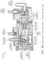
- FIGS. 2 A, 2 B, 3 and 4 show the present invention in the form of a pump generally indicated as 10 .
- FIG. 2 A A first figure.
- FIG. 2 A shows the major component layout of the pump 10 that includes the gas housing 20 and a liquid housing 30 .
- a slide valve assembly 22 configured therein, a gas housing cover 24 , and a piston shaft/actuator slide assembly 26 .
- the slide valve assembly 22 may be configured with a block or housing assembly 22 a and an actuator assembly 22 b .
- the block or housing assembly 22 a may include a slide valve housing 22 a 1 , a block plate 22 a 2 and a gasket block 22 a 3 , as labeled in FIG. 2 A .
- the block or housing assembly 22 a may also includes a gas opening 22 a 4 , a gas opening 22 a 4 ′, a gas openings 22 a 5 , a gas openings 22 a 5 ′, a gas opening 22 a 6 , a gas opening 22 a 6 ′, and a gas channel or passageway 22 a 7 , a gas channel or passageway 22 a 7 ′, which are all shown and labeled in relation to FIGS. 5 and 6 .
- the actuator assembly 22 b may include a slide block 22 b 1 , a lower retainer 22 b 2 , a slide spring 22 b 3 , an upper retainer 22 b 4 and a yoke 22 b 5 , which are all shown in further detail in FIG. 5 .
- reference label 22 b 8 ( FIG. 5 D ) indicates where the application of a lubricant, such as a silicon lubrication, may be applied.
- the gas housing 20 may also be configured with two gas chamber 21 a , 21 b , which are labeled and identified in FIG. 2 B .
- the piston/actuator slide assembly 26 may include a piston shaft coupling member 26 a that slides along an actuator slide 26 b as the slide valve assembly 22 slides back and forth (i.e., from left to right) when moving from the pressure stroke ( FIG. 3 ) to the suction stroke ( FIG. 4 ), and vice versa.
- the actuator slide 26 b may be mounting between suitable portions of the gas housing 20 , e.g., consistent with that shown in FIGS. 2 A, 2 B, 3 and 4 .
- a piston/diaphragm assembly 32 inside the liquid housing 30 , the following components may be arranged: a piston/diaphragm assembly 32 , a piston shaft 34 , a spring 36 and check valves 38 a , 38 b .
- the piston/diaphragm assembly 32 may include a piston 32 a and a diaphragm 32 b , as labeled in FIG. 2 A .
- the diaphragm 32 b is shown in FIGS. 2 A, 2 B and 3 , but not shown in FIG. 4 ).
- the piston shaft 34 may be coupled on one end to the piston support member 26 a , and may be coupled on the other end to the piston 32 a , as shown.
- the diaphragm 32 b may be coupled between the gas housing 20 and the liquid housing 30 , as shown in FIGS. 2 A, 2 B and 3 .
- a slipper seal 28 may be configured between part 20 a of the gas housing 20 and the piston shaft 34 between gas chambers 21 a , 21 b (e.g., see FIG. 2 A ).
- FIG. 2 B shows the porting and fluid areas of the pump 10 that includes a gas exhaust fitting 60 , a gas-in fitting 62 , a syrup outlet fitting 64 and a syrup suction fitting 66 .
- FIG. 2 B also shows and identifies the gas chamber 21 a (No. 1), the gas chamber 21 b (No. 2) and a liquid chamber 31 a.
- FIG. 3 The Pressure Stroke
- FIG. 3 shows the pump 10 during a pressure stroke, i.e. when gas flows into the gas chamber 20 causing liquid to flow out of the liquid chamber 31 a of the pump 10 .
- FIG. 3 shows steps of the pressure stroke, as follows:
- FIG. 4 The Suction Stroke
- FIG. 4 shows the pump 10 during a suction stroke, i.e. gas flowing out from the pump 10 and liquid flowing into of the pump 10 .
- FIG. 4 shows steps of the suction stroke, as follows:
- the slide spring 22 b 3 is configured under compression between the lower and upper retainers 22 b 2 and 22 b 4 , and in relation to the sliding block 22 a 1 and the yoke 22 b 5 , e.g., when in either the position in the pressure stroke ( FIG. 3 ) or the position in the suction stroke ( FIG. 4 ).
- the slide spring 22 b 3 is further compressed, then relaxes once the actuator assembly 22 b has fully rotated or translated back to the position in the other position.
- the slide spring 22 b 3 provides the resilience or elasticity to allow the rotation or translation back and forth between the positions in FIGS. 3 and 4 .
- the slide valve assembly 22 may include one or more components made of ceramic.
- the slide block or gas valve 22 b 1 may include, or take the form of, a ceramic slide type gas valve.
- a ceramic may take the form of a product or an article of manufacture made from a nonmetallic material by firing at a high temperature, such as porcelain.
- porcelain may be made from, or consistent of, kaolin, quartz and/or feldspar that is fired at high temperatures.
- the scope of the invention is not intended to be limited to any particular type or kind of ceramic or ceramic material that is now known or later developed in the art.
- FIGS. 7 A and 7 B show the gas opening 22 a 5 ′, the gas opening 22 a 6 ′ and the gas channel 22 a 7 ′. These openings and channel are closed off in a single pump configuration like that shown in FIGS. 2 A, 2 B 3 and 4 , but and may be used in a two pump configuration.
- either the slide block 22 b 1 blocks the gas opening 22 a 5 ′ when the slide block 22 b 1 is in the positions in FIGS. 3 and 4
- the gas opening 22 a 6 ′ is blocked off, e.g., with a cap (not shown).
- possible applications may include: BIB pumping, transfer pumping, or beverage dosing.
- the present invention may also be used in, or form part of, or used in conjunction with, other fluid handling applications.
- the scope of the invention is also not intended to be limited to being implemented in any particular type or kind of pump either now known or later developed in the future, and may include other diaphragm pumps, etc.
Landscapes
- Engineering & Computer Science (AREA)
- Mechanical Engineering (AREA)
- General Engineering & Computer Science (AREA)
- Reciprocating Pumps (AREA)
Abstract
A pump includes a liquid housing having a liquid chamber with a piston/diaphragm assembly arranged therein that responds to a suction stroke and draws liquid into the liquid chamber, and responds to a pressure stroke and provides liquid from the liquid chamber; and a gas housing having a slide valve assembly separating first and second gas chambers. The slide valve assembly responds to a suction-to-pressure-force at the suction stroke conclusion, changes from a suction-to-pressure stroke state, provides gas from the first to second gas chamber through the slide valve assembly, and provides the pressure stroke so liquid passes from the liquid chamber; and responds to a pressure-to-suction-force at the pressure stroke conclusion, changes from the pressure-to-suction stroke state, provides gas from the second chamber through the slide valve assembly, and provides the suction stroke so liquid is drawn into the liquid chamber.
Description
This application is a continuation application of, and claims benefit to, patent application Ser. No. 14/733,481, filed 8 Jun. 2015, which claims benefit to provisional patent application Ser. No. 62/008,782 (911-005-074-1 (FFLJX0010US)), filed 6 Jun. 2014; which is incorporated by reference in its entirety.
The present invention relates to a pump; and more particularly to a pump for controlling the provisioning of syrup from a syrup bag to a fluid dispenser.
Pumps are known in the art that are air-driven double piston/diaphragm pumps such as the model G & N series BIB pumps that are distributed by the assignee of the present invention. Problems and shortcomings of these known pumps include that they require more parts and more space than is otherwise needed to provide the required output or pumping. For the required output (which is relatively small), these pumps are over rated and therefore not an ideal solution in terms of cost and space. FIG. 1 shows an existing product offering having a spool type gas valve that has been in existence for more than 15 years.
There is a need in the industry to provide a solution to the aforementioned problem in terms of cost and space.
The present invention provide a single piston diaphragm pump that provides a solution to the aforementioned problem in the art in terms of cost and space.
By way of example, and according to some embodiments, the present invention may include, or take the form of, apparatus such as a pump featuring a liquid housing configured with a liquid chamber in combination a gas housing configured with a gas chamber.
The liquid chamber may be configured with a single piston/diaphragm assembly arranged therein to respond to a suction stroke and draw liquid into the liquid chamber, and configured to respond to a pressure stroke and provide the liquid from the liquid chamber.
The gas housing may include a slide valve assembly that fluidicly communicates with a first gas chamber and a second gas chamber. The slide valve assembly may be configured to respond to a suction-to-pressure stroke force at a conclusion of the suction stroke, change from a suction stroke state to a pressure stroke state, provide gas from the first gas chamber to the second gas chamber through the slide valve assembly, and provide the pressure stroke so the liquid passes from the liquid chamber. The slide valve assembly may also be configured to respond to a pressure-to-suction stroke force at a corresponding conclusion of the pressure stroke, change from the pressure stroke state to the suction stroke state, provide gas from the second gas chamber to atmosphere through the slide valve assembly, and provide the suction stroke so the liquid is drawn into the liquid chamber.
The present invention may include one or more of the following features:
The slide valve assembly may include a block or housing assembly and an actuator assembly; the block or housing assembly may include a slide valve housing configured with a cavity, recess or channel; and the actuator assembly may include a slide block configured to slide in the cavity, recess or channel of the slide valve housing, an actuator combination having a slide spring arranged between a lower retainer and an upper retainer, and a yoke configured with an opening to contain the actuator combination under compression and also configured to couple to the slide valve housing allowing the slide valve assembly to change between the pressure stroke state and the suction stroke state respectively in response to the suction-to-pressure force and the pressure-to-suction force.
The actuator assembly may be configured to slide, rotate or translate in relation to the block or housing assembly in response to the suction-to-pressure force and the pressure-to-suction force.
The first gas chamber may be configured to receive the gas via a gas-in fitting in response to the suction-to-pressure force at the conclusion of the suction stroke.
The valve slide assembly may be configured to provide the gas via a gas exhaust fitting to atmosphere in response to the pressure-suction force at the conclusion of the pressure stroke.
During the pressure stroke, the valve slide assembly may be positioned so that gas is routed from the first gas chamber thru the slide valve assembly to the second gas chamber.
During the suction stroke, the valve slide assembly may be positioned so that gas is routed from the second gas chamber thru the slide valve assembly to a gas exhaust fitting, then to atmosphere.
The single piston/diaphragm assembly may be configured to respond to the gas filling the second gas chamber, provide the pressure stroke causing a displacement of the liquid from the liquid chamber through an outlet fitting, and cause the slide valve assembly to change from the pressure stroke state to the suction stroke state at the conclusion of the pressure stroke.
The single piston/diaphragm assembly may be configured to respond to the gas being exhausted from the second chamber, provide the suction stroke, draw the liquid through a liquid inlet fitting and into the liquid chamber, and cause the slide valve assembly to change from the suction stroke state to the pressure stroke state at the conclusion of the suction stroke.
The single piston/diaphragm assembly may include a spring configured to respond to the pressure stroke, compress storing energy for the suction stroke, and provide the suction stroke at the corresponding conclusion of the pressure stroke.
The single piston/diaphragm assembly may be configured between the second gas chamber and the liquid chamber to respond to the suction stroke and move so as to expand the volume of the liquid chamber drawing fluid into the liquid chamber.
The slide valve assembly may include at least one component made of ceramic. By way of example, the slide block may be made of ceramic.
The single piston/diaphragm assembly may include a piston and a diaphragm, the piston being coupled to the slide valve assembly via a piston shaft/actuator slide assembly, and the diaphragm being coupled between the gas housing and the liquid housing.
Possible applications may include, e.g., bag-in-box fluid transfer, bottled water dispensers, coffee machine auto-refill, beverage dispensers, general fluid transfer, water pressure systems, or chemical spraying systems.
The drawing includes FIGS. 1-6 , which are not necessarily drawn to scale, as follows:
In the drawing, the Figures have reference numerals and lead lines associated with the various elements shown therein. For the sake of reducing clutter in the drawing, and also improving readability when the specification is read in conjunction with the drawing, every Figure does not include every reference numeral and lead line associated with every element shown therein. Moreover, as a person skilled in the art would appreciate, some elements that do not form part of the underlying point of novelty of the present invention are not provided with a reference numeral and lead line.
By way of example, inside the gas housing 20, the following components may be arranged: a slide valve assembly 22 configured therein, a gas housing cover 24, and a piston shaft/actuator slide assembly 26. The slide valve assembly 22 may be configured with a block or housing assembly 22 a and an actuator assembly 22 b. The block or housing assembly 22 a may include a slide valve housing 22 a 1, a block plate 22 a 2 and a gasket block 22 a 3, as labeled in FIG. 2A . The block or housing assembly 22 a may also includes a gas opening 22 a 4, a gas opening 22 a 4′, a gas openings 22 a 5, a gas openings 22 a 5′, a gas opening 22 a 6, a gas opening 22 a 6′, and a gas channel or passageway 22 a 7, a gas channel or passageway 22 a 7′, which are all shown and labeled in relation to FIGS. 5 and 6 .
As labeled in FIG. 2A , the actuator assembly 22 b may include a slide block 22 b 1, a lower retainer 22 b 2, a slide spring 22 b 3, an upper retainer 22 b 4 and a yoke 22 b 5, which are all shown in further detail in FIG. 5 . (By way of example, reference label 22 b 8 (FIG. 5D ) indicates where the application of a lubricant, such as a silicon lubrication, may be applied.) The gas housing 20 may also be configured with two gas chamber 21 a, 21 b, which are labeled and identified in FIG. 2B . The piston/actuator slide assembly 26 may include a piston shaft coupling member 26 a that slides along an actuator slide 26 b as the slide valve assembly 22 slides back and forth (i.e., from left to right) when moving from the pressure stroke (FIG. 3 ) to the suction stroke (FIG. 4 ), and vice versa. The actuator slide 26 b may be mounting between suitable portions of the gas housing 20, e.g., consistent with that shown in FIGS. 2A, 2B, 3 and 4 .
By way of example, inside the liquid housing 30, the following components may be arranged: a piston/diaphragm assembly 32, a piston shaft 34, a spring 36 and check valves 38 a, 38 b. The piston/diaphragm assembly 32 may include a piston 32 a and a diaphragm 32 b, as labeled in FIG. 2A . (The diaphragm 32 b is shown in FIGS. 2A, 2B and 3 , but not shown in FIG. 4 ). The piston shaft 34 may be coupled on one end to the piston support member 26 a, and may be coupled on the other end to the piston 32 a, as shown. The diaphragm 32 b may be coupled between the gas housing 20 and the liquid housing 30, as shown in FIGS. 2A, 2B and 3 . A slipper seal 28 may be configured between part 20 a of the gas housing 20 and the piston shaft 34 between gas chambers 21 a, 21 b (e.g., see FIG. 2A ).
By way of example, FIG. 3 shows steps of the pressure stroke, as follows:
-
- 1. Gas fills the
first gas chamber 21 a (no. 1) via the gas inlet fitting 62 (FIG. 2B ). - 2. Gas is then routed thru the slide valve assembly 22 (see arrows ps1) from the
first gas chamber 21 a to thesecond gas chamber 21 b (no. 2). In operation, theactuator assembly 22 a is positioned to allow the gas to pass from thegas chamber 21 a (no. 1) to thegas chamber 21 b (no. 2), e.g., via a gas housing passage or channel that may be formed intopart 20 b of gas housing 20 (indicated by the flow using arrow ps1). By way of example, when theslide valve assembly 22 slides, rotates or translates into the position shown inFIG. 3 , theslide block 22b 1 is configured to allow gas to flow from thefirst gas chamber 21 a through thevalve slide housing 22 a 1, through thegas opening 22 a 5 (FIGS. 7A, 7B ), through the gas housing passage orchannel 22 a 7 (FIG. 7B ), out gas opening 22 a 6, through the gas housing passage or channel in the gas housing 20, and into thesecond gas chamber 21 b as indicated by arrow ps1. In effect, when theslide block 22b 1 is in the position inFIG. 3 , part of theslide block 22b 1 is blocking the middle gas opening 22 a 4′, so the gas cannot flow through thegas opening 22 a 4′ (FIG. 7A, 7B ) and out via thegas opening 22 a 4 (FIG. 5D, 6B ) to the gas exhaust fitting 60. - 3. As gas fills the
second gas chamber 21 b (no. 2), pressure acts on the piston/diaphragm 32 (FIG. 2A ) causing it to travel to the right as shown (see arrow ps2). - 4. As the
piston 32 a travels rightward, the liquid contents of theliquid chamber 31 a are displaced through the check valve 28 a and discharged out the liquid/syrup outlet fitting 64. In addition, thespring 36 is compressed storing energy for the suction stroke shown and described in relation toFIG. 4 .
- 1. Gas fills the
-
- 1. At the end of the pressure stroke, the
slide valve assembly 22 slides, rotates to translates into the position shown inFIG. 4 , theslide block 22b 1 changes state, and the gas in thesecond gas chamber 21 b (no. 2) is routed back thru the gas housing passage or channel in thepart 20 b of the gas housing 20, through the slide valve assembly 22 (see arrow ss1), through thegas opening 22 a 4′ (FIG. 7A or 7B ), out thegas opening 22 a 4 (FIG. 5B or 6B ) and out the gas exhaust fitting 60, e.g., to atmosphere (as gas flow exhaust, see arrows ss2). In effect, when theslide block 22b 1 is in the position inFIG. 4 , part of theslide block 22b 1 is blocking thegas opening 22 a 5, so gas is not flowing from thesecond gas chamber 21 b back into thefirst gas chamber 21 a. - 2. The pressure in the
second gas chamber 21 b (no. 2) drops quickly to zero and thespring 36 acts on the piston/diaphragm 32 (see arrows ss3) inducing travel leftward. - 3. As the piston/
diaphragm 32 travels leftwards (see arrow ss4), theliquid chamber 31 a is expanded drawing liquid (e.g., syrup) via the syrup suction fitting 66 into theliquid chamber 31 a (see arrow ss5) thru thecheck valve 38 b. - 4. At the conclusion of the suction stroke, then the entire mechanism will change to the pressure stroke (see
FIG. 3 ), i.e., theslide valve assembly 22 slides, rotates or translates into the position shown inFIG. 3 , theslide block 22b 1 changes state back to that shown inFIG. 3C .
- 1. At the end of the pressure stroke, the
The Actuator Assembly 22 b
In the actuator assembly 22 b, the slide spring 22 b 3 is configured under compression between the lower and upper retainers 22 b 2 and 22 b 4, and in relation to the sliding block 22 a 1 and the yoke 22 b 5, e.g., when in either the position in the pressure stroke (FIG. 3 ) or the position in the suction stroke (FIG. 4 ). When the actuator assembly 22 b rotates or translates from the position in the pressure stroke (FIG. 3 ) to the position in the suction stroke (FIG. 4 ), or vice versa, the slide spring 22 b 3 is further compressed, then relaxes once the actuator assembly 22 b has fully rotated or translated back to the position in the other position. In effect, the slide spring 22 b 3 provides the resilience or elasticity to allow the rotation or translation back and forth between the positions in FIGS. 3 and 4 .
A Ceramic Slide Type Gas Valve 22 b
By way of example, the slide valve assembly 22 may include one or more components made of ceramic. For example, the slide block or gas valve 22 b 1 may include, or take the form of, a ceramic slide type gas valve. As a person skilled in the art would appreciate, a ceramic may take the form of a product or an article of manufacture made from a nonmetallic material by firing at a high temperature, such as porcelain. In particular, porcelain may be made from, or consistent of, kaolin, quartz and/or feldspar that is fired at high temperatures. The scope of the invention is not intended to be limited to any particular type or kind of ceramic or ceramic material that is now known or later developed in the art.
Applications
By way of example, possible applications may include: BIB pumping, transfer pumping, or beverage dosing.
The present invention may also be used in, or form part of, or used in conjunction with, other fluid handling applications. The scope of the invention is also not intended to be limited to being implemented in any particular type or kind of pump either now known or later developed in the future, and may include other diaphragm pumps, etc.
The Scope of the Invention
While the invention has been described with reference to an exemplary embodiment, it will be understood by those skilled in the art that various changes may be made and equivalents may be substituted for elements thereof without departing from the scope of the invention. In addition, may modifications may be made to adapt a particular situation or material to the teachings of the invention without departing from the essential scope thereof. Therefore, it is intended that the invention not be limited to the particular embodiment(s) disclosed herein as the best mode contemplated for carrying out this invention.
Claims (17)
1. A pump (10) comprising:
a gas housing (20) having a first gas chamber (21 a), a second gas chamber (21 b), a gas exhaust fitting (60) configured to provide inlet gas to the first gas chamber (21 a), and a gas inlet fitting (62) configured to provide outlet gas from the second gas chamber (21 b),
a liquid housing (30) having a liquid chamber (31 a), a liquid outlet fitting (64) configured to provide liquid from the liquid chamber (31 a), and a liquid suction fitting (66) configured to provide the liquid to the liquid chamber (31 a), having a single piston/diaphragm assembly (32) with a spring (36) and being arranged between the second gas chamber (21 b) and the liquid chamber (31 a), the single piston/diaphragm assembly (32) drawing the liquid from the liquid inlet fitting (66) into the liquid chamber (31 a) during a suction stroke and providing the liquid from the liquid chamber (31 a) to the outlet fitting (64) during a pressure stroke; the spring (36) being configured in the liquid chamber (31 a) to store energy during the pressure stroke and provides the suction stroke; and
a slide valve assembly (22) being arranged in the first gas chamber 21 a and being movable between a pressure stroke state and a suction stroke state for alternately providing pressurized gas to the second gas chamber (21 b) so that the liquid passes from the liquid chamber (31 a) to the liquid outlet fitting (64), and providing gas from the second gas chamber (21 b) to atmosphere, so that the spring (36) provides the suction stroke and liquid is drawn from the liquid inlet fitting (66) into the liquid chamber (31 a), characterized in that
the slide valve assembly (22) comprises a block or housing assembly (22 a) and an actuator assembly (22 b);
the block or housing assembly (22 a) comprises a slide valve housing (22 a 1) configured with a cavity;
the actuator assembly (22 b) comprises a slide block (22 b 1) configured to slide in the cavity of the slide valve housing (22 a 1);
the actuator assembly (22 b) having a slide spring (22 b 3) arranged between a lower retainer (22 b 2) and an upper retainer (22 b 4) forming an actuator combination under compression, and a yoke (22 b 5) configured with an opening to contain the actuator combination under compression; and
a piston shaft/actuator slide assembly (26) coupling the yoke (22 b 5) and the single piston/diaphragm assembly (32) causing the slide valve assembly (22) to change between the pressure stroke state and the suction stroke state.
2. A pump (10) according to claim 1 , wherein the actuator assembly (22 b) is configured to slide in relation to the block or housing assembly (22 a) in response to the suction-to-pressure force and the pressure-to-suction force.
3. A pump (10) according to claim 1 , wherein the first gas chamber (21 a) is configured to receive the gas via the gas inlet fitting (62) in response to the suction-to-pressure force at the conclusion of the suction stroke.
4. A pump (10) according to claim 1 , wherein the slide valve assembly (22) is configured to provide the gas via the gas exhaust fitting (60) to atmosphere in response to the pressure-suction force at the conclusion of the pressure stroke.
5. A pump (10) according to claim 1 , wherein, during the pressure stroke, the slide valve assembly (22) is positioned so that gas is routed from the first gas chamber (21 a) thru the slide valve assembly (22) to the second gas chamber (21 b).
6. A pump (10) according to claim 1 , wherein, during the suction stroke, the slide valve assembly (22) is positioned so that gas is routed from the second gas chamber (21 b) thru the slide valve assembly (22) to the gas exhaust fitting (60).
7. A pump (10) according to claim 1 , wherein the slide valve assembly (22) comprises at least one component (22 b) made of ceramic.
8. A pump (10) according to claim 7 , wherein the slide block (22 b 1) is made of ceramic.
9. A pump (10) according to claim 2 , wherein the single piston/diaphragm assembly (32) comprises a piston (32 a) and a diaphragm (32 b), the piston (32 a) being coupled to the slide valve assembly (22) via a piston shaft/actuator slide assembly (26), and the diaphragm (32 b) being coupled between the gas housing (20) and the liquid housing (30).
10. A pump (10) comprising:
a gas housing (20) having a first gas chamber (21 a), a second gas chamber (21 b), a gas exhaust fitting (60) configured to provide inlet gas to the first gas chamber (21 a), and a gas inlet fitting (62) configured to provide outlet gas from the second gas chamber (21 b);
a liquid housing (30) having a liquid chamber (31 a), a liquid outlet fitting (64) configured to provide liquid from the liquid chamber (31 a), and a liquid suction fitting (66) configured to provide the liquid to the liquid chamber (31 a), having a single piston/diaphragm assembly (32) with a spring (36) and being arranged between the second gas chamber (21 b) and the liquid chamber (31 a), the single piston/diaphragm assembly (32) drawing the liquid from the liquid inlet fitting (66) into the liquid chamber (31 a) during a suction stroke and providing the liquid from the liquid chamber (31 a) to the outlet fitting (64) during a pressure stroke; the spring (36) being configured in the liquid chamber (31 a) to store energy during the pressure stroke and provides the suction stroke; and
a slide valve assembly (22) being arranged in the first gas chamber 21 a and being movable between a pressure stroke state and a suction stroke state for alternately providing pressurized gas to the second gas chamber (21 b) so that the liquid passes from the liquid chamber (31 a) to the liquid outlet fitting (64), and providing gas from the second gas chamber (21 b) to atmosphere, so that the spring (36) provides the suction stroke and liquid is drawn from the liquid inlet fitting (66) into the liquid chamber (31 a), characterized in that
the slide valve assembly (22) comprises a block or housing assembly (22 a) and an actuator assembly (22 b);
the block or housing assembly (22 a) comprises a slide valve housing (22 a 1) configured with a cavity;
the actuator assembly (22 b) comprises a slide block (22 b 1) configured to slide in the cavity of the slide valve housing (22 a 1);
the actuator assembly (22 b) having a slide spring (22 b 3) arranged between a lower retainer (22 b 2) and an upper retainer (22 b 4) forming an actuator combination under compression, and a yoke (22 b 5) configured with an opening to contain the actuator combination under compression;
a piston shaft/actuator slide assembly (26) coupling the yoke (22 b 5) and the single piston/diaphragm assembly (32) causing the slide valve assembly (22) to change between the pressure stroke state and the suction stroke state; and
the single piston/diaphragm assembly (32) comprises a piston (32 a) and a diaphragm (32 b), the piston (32 a) being coupled to the slide valve assembly (22) via a piston shaft/actuator slide assembly (26), and the diaphragm (32 b) being coupled between the gas housing (20) and the liquid housing (30).
11. A pump (10) according to claim 10 , wherein the actuator assembly (22 b) is configured to slide in relation to the block or housing assembly (22 a) in response to the suction-to-pressure force and the pressure-to-suction force.
12. A pump (10) according to claim 10 , wherein the first gas chamber (21 a) is configured to receive the gas via the gas inlet fitting (62) in response to the suction-to-pressure force at the conclusion of the suction stroke.
13. A pump (10) according to claim 10 , wherein the slide valve assembly (22) is configured to provide the gas via the gas exhaust fitting (60) to atmosphere in response to the pressure-suction force at the conclusion of the pressure stroke.
14. A pump (10) according to claim 10 , wherein, during the pressure stroke, the slide valve assembly (22) is positioned so that gas is routed from the first gas chamber (21 a) thru the slide valve assembly (22) to the second gas chamber (21 b).
15. A pump (10) according to claim 10 , wherein, during the suction stroke, the slide valve assembly (22) is positioned so that gas is routed from the second gas chamber (21 b) thru the slide valve assembly (22) to the gas exhaust fitting (60).
16. A pump (10) according to claim 10 , wherein the slide valve assembly (22) comprises at least one component (22 b) made of ceramic.
17. A pump (10) according to claim 16 , wherein the slide block (22 b 1) is made of ceramic.
Priority Applications (1)
| Application Number | Priority Date | Filing Date | Title |
|---|---|---|---|
| US17/488,669 US11592013B2 (en) | 2014-06-06 | 2021-09-29 | Single piston foundation bag-in-box (BIB) pump |
Applications Claiming Priority (3)
| Application Number | Priority Date | Filing Date | Title |
|---|---|---|---|
| US201462008782P | 2014-06-06 | 2014-06-06 | |
| US14/733,481 US20150377224A1 (en) | 2014-06-06 | 2015-06-08 | Single piston foundation bag-in-box (bib) pump |
| US17/488,669 US11592013B2 (en) | 2014-06-06 | 2021-09-29 | Single piston foundation bag-in-box (BIB) pump |
Related Parent Applications (1)
| Application Number | Title | Priority Date | Filing Date |
|---|---|---|---|
| US14/733,481 Continuation US20150377224A1 (en) | 2014-06-06 | 2015-06-08 | Single piston foundation bag-in-box (bib) pump |
Publications (2)
| Publication Number | Publication Date |
|---|---|
| US20220128048A1 US20220128048A1 (en) | 2022-04-28 |
| US11592013B2 true US11592013B2 (en) | 2023-02-28 |
Family
ID=54767612
Family Applications (2)
| Application Number | Title | Priority Date | Filing Date |
|---|---|---|---|
| US14/733,481 Abandoned US20150377224A1 (en) | 2014-06-06 | 2015-06-08 | Single piston foundation bag-in-box (bib) pump |
| US17/488,669 Active US11592013B2 (en) | 2014-06-06 | 2021-09-29 | Single piston foundation bag-in-box (BIB) pump |
Family Applications Before (1)
| Application Number | Title | Priority Date | Filing Date |
|---|---|---|---|
| US14/733,481 Abandoned US20150377224A1 (en) | 2014-06-06 | 2015-06-08 | Single piston foundation bag-in-box (bib) pump |
Country Status (3)
| Country | Link |
|---|---|
| US (2) | US20150377224A1 (en) |
| EP (1) | EP3152440B1 (en) |
| WO (1) | WO2015188185A2 (en) |
Families Citing this family (1)
| Publication number | Priority date | Publication date | Assignee | Title |
|---|---|---|---|---|
| WO2017173077A1 (en) * | 2016-03-30 | 2017-10-05 | Flow Control Llc. | Modular bib pump |
Citations (24)
| Publication number | Priority date | Publication date | Assignee | Title |
|---|---|---|---|---|
| US2920575A (en) | 1957-06-03 | 1960-01-12 | Taco Heaters Inc | Pump |
| US3699846A (en) | 1970-12-30 | 1972-10-24 | Stewart Warner Corp | Air motor |
| US3771907A (en) | 1971-09-13 | 1973-11-13 | Reynolds Products | Simplified positive displacement syrup pump assembly for drink machines |
| US3782863A (en) | 1971-11-16 | 1974-01-01 | Rupp Co Warren | Slide valve apparatus |
| US4008984A (en) | 1975-10-23 | 1977-02-22 | Scholle William R | Pump apparatus |
| US4436493A (en) | 1979-09-21 | 1984-03-13 | The Coca-Cola Company | Self contained pump and reversing mechanism therefor |
| US4540349A (en) | 1984-05-16 | 1985-09-10 | Du Benjamin R | Air driven pump |
| US4681518A (en) | 1985-02-19 | 1987-07-21 | The Coca-Cola Company | Single-acting, gas operated pump |
| US4828465A (en) | 1985-02-19 | 1989-05-09 | The Coca-Cola Company | Single-acting, gas-operated pump |
| US5083906A (en) * | 1990-09-11 | 1992-01-28 | Du Benjamin R | Fluid pump |
| US5470209A (en) | 1993-10-13 | 1995-11-28 | Shurflo Pump Manufacturing Co. | Offset reciprocable device |
| WO1996010534A1 (en) | 1994-09-30 | 1996-04-11 | Rosereed Ltd | Double diaphragm pump |
| US5664940A (en) | 1995-11-03 | 1997-09-09 | Flojet Corporation | Gas driven pump |
| US5667105A (en) | 1994-05-12 | 1997-09-16 | Shurflo Pump Manufacturing Co. | Portion control valve and system and method utilizing the same |
| US6234349B1 (en) | 1999-10-19 | 2001-05-22 | Sterling Beverage Systems, Inc. | Self-contained high pressure pneumatic beverage dispensing system |
| US20050072800A1 (en) | 2003-09-19 | 2005-04-07 | Smith Clyde M. | Fluid powered proportioning pump and post-mix beverage dispenser system using same |
| US7225830B1 (en) | 2005-02-09 | 2007-06-05 | Kershaw Charles H | Fluid control valve |
| US20090126581A1 (en) | 2005-05-25 | 2009-05-21 | Friesland Brands B.V. | Dispenser system using gas injection |
| US20100176147A1 (en) | 2007-05-31 | 2010-07-15 | Heineken Supply Chain B.V. | Apparatus and method for dispensing beverage |
| US8162294B2 (en) | 2006-04-21 | 2012-04-24 | Ludgate 332 Ltd | Water carbonation apparatus |
| US20120138632A1 (en) | 2010-12-02 | 2012-06-07 | Pepsico, Inc. | Hot and cold beverage dispenser |
| US20130209280A1 (en) | 2010-08-26 | 2013-08-15 | Prominent Dosiertechnik Gmbh | Membrane Pump Having an Inertially Controlled Leakage Compensation Valve |
| WO2013155079A1 (en) | 2012-04-09 | 2013-10-17 | Flow Control Llc. | Air operated diaphragm pump |
| US20140072455A1 (en) | 2012-04-03 | 2014-03-13 | Benjamin R. Du | Bag in box beverage pump |
-
2015
- 2015-06-08 WO PCT/US2015/034703 patent/WO2015188185A2/en not_active Ceased
- 2015-06-08 EP EP15803683.0A patent/EP3152440B1/en active Active
- 2015-06-08 US US14/733,481 patent/US20150377224A1/en not_active Abandoned
-
2021
- 2021-09-29 US US17/488,669 patent/US11592013B2/en active Active
Patent Citations (26)
| Publication number | Priority date | Publication date | Assignee | Title |
|---|---|---|---|---|
| US2920575A (en) | 1957-06-03 | 1960-01-12 | Taco Heaters Inc | Pump |
| US3699846A (en) | 1970-12-30 | 1972-10-24 | Stewart Warner Corp | Air motor |
| US3771907A (en) | 1971-09-13 | 1973-11-13 | Reynolds Products | Simplified positive displacement syrup pump assembly for drink machines |
| US3782863A (en) | 1971-11-16 | 1974-01-01 | Rupp Co Warren | Slide valve apparatus |
| US4008984A (en) | 1975-10-23 | 1977-02-22 | Scholle William R | Pump apparatus |
| US4436493A (en) | 1979-09-21 | 1984-03-13 | The Coca-Cola Company | Self contained pump and reversing mechanism therefor |
| US4540349A (en) | 1984-05-16 | 1985-09-10 | Du Benjamin R | Air driven pump |
| US4681518A (en) | 1985-02-19 | 1987-07-21 | The Coca-Cola Company | Single-acting, gas operated pump |
| US4828465A (en) | 1985-02-19 | 1989-05-09 | The Coca-Cola Company | Single-acting, gas-operated pump |
| US5083906A (en) * | 1990-09-11 | 1992-01-28 | Du Benjamin R | Fluid pump |
| US5470209A (en) | 1993-10-13 | 1995-11-28 | Shurflo Pump Manufacturing Co. | Offset reciprocable device |
| US5667105A (en) | 1994-05-12 | 1997-09-16 | Shurflo Pump Manufacturing Co. | Portion control valve and system and method utilizing the same |
| WO1996010534A1 (en) | 1994-09-30 | 1996-04-11 | Rosereed Ltd | Double diaphragm pump |
| US5664940A (en) | 1995-11-03 | 1997-09-09 | Flojet Corporation | Gas driven pump |
| US5833439A (en) * | 1995-11-03 | 1998-11-10 | Du; Benjamin R. | Slide valve of a gas driven pump |
| US6234349B1 (en) | 1999-10-19 | 2001-05-22 | Sterling Beverage Systems, Inc. | Self-contained high pressure pneumatic beverage dispensing system |
| US20050072800A1 (en) | 2003-09-19 | 2005-04-07 | Smith Clyde M. | Fluid powered proportioning pump and post-mix beverage dispenser system using same |
| JP2005121013A (en) | 2003-09-19 | 2005-05-12 | Clyde M Smith | Fluid driven type proportioning pump and post-mix beverage dispenser system using the proportioning pump |
| US7225830B1 (en) | 2005-02-09 | 2007-06-05 | Kershaw Charles H | Fluid control valve |
| US20090126581A1 (en) | 2005-05-25 | 2009-05-21 | Friesland Brands B.V. | Dispenser system using gas injection |
| US8162294B2 (en) | 2006-04-21 | 2012-04-24 | Ludgate 332 Ltd | Water carbonation apparatus |
| US20100176147A1 (en) | 2007-05-31 | 2010-07-15 | Heineken Supply Chain B.V. | Apparatus and method for dispensing beverage |
| US20130209280A1 (en) | 2010-08-26 | 2013-08-15 | Prominent Dosiertechnik Gmbh | Membrane Pump Having an Inertially Controlled Leakage Compensation Valve |
| US20120138632A1 (en) | 2010-12-02 | 2012-06-07 | Pepsico, Inc. | Hot and cold beverage dispenser |
| US20140072455A1 (en) | 2012-04-03 | 2014-03-13 | Benjamin R. Du | Bag in box beverage pump |
| WO2013155079A1 (en) | 2012-04-09 | 2013-10-17 | Flow Control Llc. | Air operated diaphragm pump |
Non-Patent Citations (3)
| Title |
|---|
| flojel.com "T5000 Series CO2 Operated Bag-In-Box Pump" https://www.xylemflowcontrol.com/files/T5000_SS_950-0146.pdf. 950-0146 Rev B. 1/12; Jan. 2012. |
| JP2005121013 English Language Abstract (2 pages); Dec. 5, 2005. |
| manitowocbeverage.com "HeavyDuty Advantage BIB Gas Pump" http://www.manitowocbeverage.com/asset/?id=zzqng. 911-532 Rev. A 03/02 which also includes Shurflow' Juice Gas pump 166-200-XX (green label) Installation adn Operation Manual, 911-437 Rev. F 1/98 pp. 1-6; and Shurflow Condiment Gas pump 166-200-XX, Installation and Operation Manual, 911-432 Rev E. 9/03 ECO 7509, pp. 1-4. Mar. 2002. |
Also Published As
| Publication number | Publication date |
|---|---|
| WO2015188185A3 (en) | 2016-03-10 |
| EP3152440C0 (en) | 2024-03-27 |
| WO2015188185A2 (en) | 2015-12-10 |
| EP3152440A4 (en) | 2018-04-04 |
| EP3152440B1 (en) | 2024-03-27 |
| EP3152440A2 (en) | 2017-04-12 |
| US20150377224A1 (en) | 2015-12-31 |
| US20220128048A1 (en) | 2022-04-28 |
Similar Documents
| Publication | Publication Date | Title |
|---|---|---|
| US8087345B2 (en) | Positive displacement injection pump | |
| RU2573018C2 (en) | Liquid dispenser | |
| US11592013B2 (en) | Single piston foundation bag-in-box (BIB) pump | |
| US7207780B2 (en) | Multiple port dual diameter pumps | |
| CN109477467A (en) | Metering mechanism for proportional pump and associated pump and method of use | |
| WO2001087495A1 (en) | Pump provided with a decompression device | |
| KR102460430B1 (en) | Dual chamber piston pump for dispensing fluid products | |
| US8876488B2 (en) | Positive air shut off device for bag-in-box pump | |
| US547012A (en) | Edward j | |
| NL2011347C2 (en) | Fluid dose-measuring device. | |
| US691343A (en) | Steam-pump. | |
| JP6855005B2 (en) | Energy pump | |
| US454646A (en) | Valve of pumps for moving gaseous bodies | |
| US475296A (en) | ohamberlin | |
| US712009A (en) | Reducing-valve. | |
| US230149A (en) | powers | |
| US698400A (en) | Vacuum-pump. | |
| US578002A (en) | Balancing apparatus for pumps | |
| CN111065466A (en) | Fluid Dispenser with Zero Displacement Seal | |
| US204680A (en) | Improvement in liquid-forcing apparatus | |
| US339617A (en) | George p | |
| US444994A (en) | Hydraulic beer-pump | |
| WO2003062638A1 (en) | Liquid dispensing pump | |
| US703648A (en) | Pump. | |
| US647153A (en) | Valve and valve-actuating mechanism for pumps, &c. |
Legal Events
| Date | Code | Title | Description |
|---|---|---|---|
| FEPP | Fee payment procedure |
Free format text: ENTITY STATUS SET TO UNDISCOUNTED (ORIGINAL EVENT CODE: BIG.); ENTITY STATUS OF PATENT OWNER: LARGE ENTITY |
|
| STPP | Information on status: patent application and granting procedure in general |
Free format text: DOCKETED NEW CASE - READY FOR EXAMINATION |
|
| STPP | Information on status: patent application and granting procedure in general |
Free format text: NOTICE OF ALLOWANCE MAILED -- APPLICATION RECEIVED IN OFFICE OF PUBLICATIONS |
|
| STPP | Information on status: patent application and granting procedure in general |
Free format text: AWAITING TC RESP, ISSUE FEE PAYMENT VERIFIED |
|
| STPP | Information on status: patent application and granting procedure in general |
Free format text: PUBLICATIONS -- ISSUE FEE PAYMENT VERIFIED |
|
| STCF | Information on status: patent grant |
Free format text: PATENTED CASE |