US11584341B2 - System and method for wheel-slip prevention in railway vehicles with pneumatic brakes - Google Patents
System and method for wheel-slip prevention in railway vehicles with pneumatic brakes Download PDFInfo
- Publication number
- US11584341B2 US11584341B2 US16/737,169 US202016737169A US11584341B2 US 11584341 B2 US11584341 B2 US 11584341B2 US 202016737169 A US202016737169 A US 202016737169A US 11584341 B2 US11584341 B2 US 11584341B2
- Authority
- US
- United States
- Prior art keywords
- brake
- slip
- pneumatic brake
- wheel
- control
- Prior art date
- Legal status (The legal status is an assumption and is not a legal conclusion. Google has not performed a legal analysis and makes no representation as to the accuracy of the status listed.)
- Active, expires
Links
Images




Classifications
-
- B—PERFORMING OPERATIONS; TRANSPORTING
- B60—VEHICLES IN GENERAL
- B60T—VEHICLE BRAKE CONTROL SYSTEMS OR PARTS THEREOF; BRAKE CONTROL SYSTEMS OR PARTS THEREOF, IN GENERAL; ARRANGEMENT OF BRAKING ELEMENTS ON VEHICLES IN GENERAL; PORTABLE DEVICES FOR PREVENTING UNWANTED MOVEMENT OF VEHICLES; VEHICLE MODIFICATIONS TO FACILITATE COOLING OF BRAKES
- B60T13/00—Transmitting braking action from initiating means to ultimate brake actuator with power assistance or drive; Brake systems incorporating such transmitting means, e.g. air-pressure brake systems
- B60T13/10—Transmitting braking action from initiating means to ultimate brake actuator with power assistance or drive; Brake systems incorporating such transmitting means, e.g. air-pressure brake systems with fluid assistance, drive, or release
- B60T13/66—Electrical control in fluid-pressure brake systems
- B60T13/665—Electrical control in fluid-pressure brake systems the systems being specially adapted for transferring two or more command signals, e.g. railway systems
-
- B—PERFORMING OPERATIONS; TRANSPORTING
- B60—VEHICLES IN GENERAL
- B60T—VEHICLE BRAKE CONTROL SYSTEMS OR PARTS THEREOF; BRAKE CONTROL SYSTEMS OR PARTS THEREOF, IN GENERAL; ARRANGEMENT OF BRAKING ELEMENTS ON VEHICLES IN GENERAL; PORTABLE DEVICES FOR PREVENTING UNWANTED MOVEMENT OF VEHICLES; VEHICLE MODIFICATIONS TO FACILITATE COOLING OF BRAKES
- B60T13/00—Transmitting braking action from initiating means to ultimate brake actuator with power assistance or drive; Brake systems incorporating such transmitting means, e.g. air-pressure brake systems
- B60T13/10—Transmitting braking action from initiating means to ultimate brake actuator with power assistance or drive; Brake systems incorporating such transmitting means, e.g. air-pressure brake systems with fluid assistance, drive, or release
- B60T13/24—Transmitting braking action from initiating means to ultimate brake actuator with power assistance or drive; Brake systems incorporating such transmitting means, e.g. air-pressure brake systems with fluid assistance, drive, or release the fluid being gaseous
- B60T13/26—Compressed-air systems
- B60T13/36—Compressed-air systems direct, i.e. brakes applied directly by compressed air
- B60T13/365—Compressed-air systems direct, i.e. brakes applied directly by compressed air for railway vehicles
-
- B—PERFORMING OPERATIONS; TRANSPORTING
- B60—VEHICLES IN GENERAL
- B60T—VEHICLE BRAKE CONTROL SYSTEMS OR PARTS THEREOF; BRAKE CONTROL SYSTEMS OR PARTS THEREOF, IN GENERAL; ARRANGEMENT OF BRAKING ELEMENTS ON VEHICLES IN GENERAL; PORTABLE DEVICES FOR PREVENTING UNWANTED MOVEMENT OF VEHICLES; VEHICLE MODIFICATIONS TO FACILITATE COOLING OF BRAKES
- B60T17/00—Component parts, details, or accessories of power brake systems not covered by groups B60T8/00, B60T13/00 or B60T15/00, or presenting other characteristic features
- B60T17/18—Safety devices; Monitoring
- B60T17/22—Devices for monitoring or checking brake systems; Signal devices
- B60T17/228—Devices for monitoring or checking brake systems; Signal devices for railway vehicles
-
- B—PERFORMING OPERATIONS; TRANSPORTING
- B60—VEHICLES IN GENERAL
- B60T—VEHICLE BRAKE CONTROL SYSTEMS OR PARTS THEREOF; BRAKE CONTROL SYSTEMS OR PARTS THEREOF, IN GENERAL; ARRANGEMENT OF BRAKING ELEMENTS ON VEHICLES IN GENERAL; PORTABLE DEVICES FOR PREVENTING UNWANTED MOVEMENT OF VEHICLES; VEHICLE MODIFICATIONS TO FACILITATE COOLING OF BRAKES
- B60T8/00—Arrangements for adjusting wheel-braking force to meet varying vehicular or ground-surface conditions, e.g. limiting or varying distribution of braking force
- B60T8/17—Using electrical or electronic regulation means to control braking
- B60T8/1701—Braking or traction control means specially adapted for particular types of vehicles
- B60T8/1705—Braking or traction control means specially adapted for particular types of vehicles for rail vehicles
-
- B—PERFORMING OPERATIONS; TRANSPORTING
- B60—VEHICLES IN GENERAL
- B60T—VEHICLE BRAKE CONTROL SYSTEMS OR PARTS THEREOF; BRAKE CONTROL SYSTEMS OR PARTS THEREOF, IN GENERAL; ARRANGEMENT OF BRAKING ELEMENTS ON VEHICLES IN GENERAL; PORTABLE DEVICES FOR PREVENTING UNWANTED MOVEMENT OF VEHICLES; VEHICLE MODIFICATIONS TO FACILITATE COOLING OF BRAKES
- B60T8/00—Arrangements for adjusting wheel-braking force to meet varying vehicular or ground-surface conditions, e.g. limiting or varying distribution of braking force
- B60T8/17—Using electrical or electronic regulation means to control braking
- B60T8/175—Brake regulation specially adapted to prevent excessive wheel spin during vehicle acceleration, e.g. for traction control
-
- B—PERFORMING OPERATIONS; TRANSPORTING
- B60—VEHICLES IN GENERAL
- B60T—VEHICLE BRAKE CONTROL SYSTEMS OR PARTS THEREOF; BRAKE CONTROL SYSTEMS OR PARTS THEREOF, IN GENERAL; ARRANGEMENT OF BRAKING ELEMENTS ON VEHICLES IN GENERAL; PORTABLE DEVICES FOR PREVENTING UNWANTED MOVEMENT OF VEHICLES; VEHICLE MODIFICATIONS TO FACILITATE COOLING OF BRAKES
- B60T8/00—Arrangements for adjusting wheel-braking force to meet varying vehicular or ground-surface conditions, e.g. limiting or varying distribution of braking force
- B60T8/17—Using electrical or electronic regulation means to control braking
- B60T8/176—Brake regulation specially adapted to prevent excessive wheel slip during vehicle deceleration, e.g. ABS
-
- B—PERFORMING OPERATIONS; TRANSPORTING
- B60—VEHICLES IN GENERAL
- B60T—VEHICLE BRAKE CONTROL SYSTEMS OR PARTS THEREOF; BRAKE CONTROL SYSTEMS OR PARTS THEREOF, IN GENERAL; ARRANGEMENT OF BRAKING ELEMENTS ON VEHICLES IN GENERAL; PORTABLE DEVICES FOR PREVENTING UNWANTED MOVEMENT OF VEHICLES; VEHICLE MODIFICATIONS TO FACILITATE COOLING OF BRAKES
- B60T8/00—Arrangements for adjusting wheel-braking force to meet varying vehicular or ground-surface conditions, e.g. limiting or varying distribution of braking force
- B60T8/32—Arrangements for adjusting wheel-braking force to meet varying vehicular or ground-surface conditions, e.g. limiting or varying distribution of braking force responsive to a speed condition, e.g. acceleration or deceleration
- B60T8/321—Arrangements for adjusting wheel-braking force to meet varying vehicular or ground-surface conditions, e.g. limiting or varying distribution of braking force responsive to a speed condition, e.g. acceleration or deceleration deceleration
- B60T8/3235—Systems specially adapted for rail vehicles
-
- B—PERFORMING OPERATIONS; TRANSPORTING
- B60—VEHICLES IN GENERAL
- B60T—VEHICLE BRAKE CONTROL SYSTEMS OR PARTS THEREOF; BRAKE CONTROL SYSTEMS OR PARTS THEREOF, IN GENERAL; ARRANGEMENT OF BRAKING ELEMENTS ON VEHICLES IN GENERAL; PORTABLE DEVICES FOR PREVENTING UNWANTED MOVEMENT OF VEHICLES; VEHICLE MODIFICATIONS TO FACILITATE COOLING OF BRAKES
- B60T8/00—Arrangements for adjusting wheel-braking force to meet varying vehicular or ground-surface conditions, e.g. limiting or varying distribution of braking force
- B60T8/32—Arrangements for adjusting wheel-braking force to meet varying vehicular or ground-surface conditions, e.g. limiting or varying distribution of braking force responsive to a speed condition, e.g. acceleration or deceleration
- B60T8/321—Arrangements for adjusting wheel-braking force to meet varying vehicular or ground-surface conditions, e.g. limiting or varying distribution of braking force responsive to a speed condition, e.g. acceleration or deceleration deceleration
- B60T8/3235—Systems specially adapted for rail vehicles
- B60T8/3245—Systems specially adapted for rail vehicles responsive to the speed difference between wheels and rail, or between two wheels or two axles
-
- B—PERFORMING OPERATIONS; TRANSPORTING
- B60—VEHICLES IN GENERAL
- B60T—VEHICLE BRAKE CONTROL SYSTEMS OR PARTS THEREOF; BRAKE CONTROL SYSTEMS OR PARTS THEREOF, IN GENERAL; ARRANGEMENT OF BRAKING ELEMENTS ON VEHICLES IN GENERAL; PORTABLE DEVICES FOR PREVENTING UNWANTED MOVEMENT OF VEHICLES; VEHICLE MODIFICATIONS TO FACILITATE COOLING OF BRAKES
- B60T8/00—Arrangements for adjusting wheel-braking force to meet varying vehicular or ground-surface conditions, e.g. limiting or varying distribution of braking force
- B60T8/32—Arrangements for adjusting wheel-braking force to meet varying vehicular or ground-surface conditions, e.g. limiting or varying distribution of braking force responsive to a speed condition, e.g. acceleration or deceleration
- B60T8/321—Arrangements for adjusting wheel-braking force to meet varying vehicular or ground-surface conditions, e.g. limiting or varying distribution of braking force responsive to a speed condition, e.g. acceleration or deceleration deceleration
- B60T8/3255—Systems in which the braking action is dependent on brake pedal data
- B60T8/327—Pneumatic systems
-
- B—PERFORMING OPERATIONS; TRANSPORTING
- B61—RAILWAYS
- B61H—BRAKES OR OTHER RETARDING DEVICES SPECIALLY ADAPTED FOR RAIL VEHICLES; ARRANGEMENT OR DISPOSITION THEREOF IN RAIL VEHICLES
- B61H13/00—Actuating rail-vehicle brakes
- B61H13/34—Details
-
- B—PERFORMING OPERATIONS; TRANSPORTING
- B60—VEHICLES IN GENERAL
- B60T—VEHICLE BRAKE CONTROL SYSTEMS OR PARTS THEREOF; BRAKE CONTROL SYSTEMS OR PARTS THEREOF, IN GENERAL; ARRANGEMENT OF BRAKING ELEMENTS ON VEHICLES IN GENERAL; PORTABLE DEVICES FOR PREVENTING UNWANTED MOVEMENT OF VEHICLES; VEHICLE MODIFICATIONS TO FACILITATE COOLING OF BRAKES
- B60T2240/00—Monitoring, detecting wheel/tyre behaviour; counteracting thereof
-
- B—PERFORMING OPERATIONS; TRANSPORTING
- B60—VEHICLES IN GENERAL
- B60T—VEHICLE BRAKE CONTROL SYSTEMS OR PARTS THEREOF; BRAKE CONTROL SYSTEMS OR PARTS THEREOF, IN GENERAL; ARRANGEMENT OF BRAKING ELEMENTS ON VEHICLES IN GENERAL; PORTABLE DEVICES FOR PREVENTING UNWANTED MOVEMENT OF VEHICLES; VEHICLE MODIFICATIONS TO FACILITATE COOLING OF BRAKES
- B60T2270/00—Further aspects of brake control systems not otherwise provided for
- B60T2270/10—ABS control systems
-
- B—PERFORMING OPERATIONS; TRANSPORTING
- B60—VEHICLES IN GENERAL
- B60T—VEHICLE BRAKE CONTROL SYSTEMS OR PARTS THEREOF; BRAKE CONTROL SYSTEMS OR PARTS THEREOF, IN GENERAL; ARRANGEMENT OF BRAKING ELEMENTS ON VEHICLES IN GENERAL; PORTABLE DEVICES FOR PREVENTING UNWANTED MOVEMENT OF VEHICLES; VEHICLE MODIFICATIONS TO FACILITATE COOLING OF BRAKES
- B60T2270/00—Further aspects of brake control systems not otherwise provided for
- B60T2270/10—ABS control systems
- B60T2270/14—ABS control systems hydraulic model
-
- B—PERFORMING OPERATIONS; TRANSPORTING
- B60—VEHICLES IN GENERAL
- B60T—VEHICLE BRAKE CONTROL SYSTEMS OR PARTS THEREOF; BRAKE CONTROL SYSTEMS OR PARTS THEREOF, IN GENERAL; ARRANGEMENT OF BRAKING ELEMENTS ON VEHICLES IN GENERAL; PORTABLE DEVICES FOR PREVENTING UNWANTED MOVEMENT OF VEHICLES; VEHICLE MODIFICATIONS TO FACILITATE COOLING OF BRAKES
- B60T2270/00—Further aspects of brake control systems not otherwise provided for
- B60T2270/20—ASR control systems
-
- B—PERFORMING OPERATIONS; TRANSPORTING
- B60—VEHICLES IN GENERAL
- B60T—VEHICLE BRAKE CONTROL SYSTEMS OR PARTS THEREOF; BRAKE CONTROL SYSTEMS OR PARTS THEREOF, IN GENERAL; ARRANGEMENT OF BRAKING ELEMENTS ON VEHICLES IN GENERAL; PORTABLE DEVICES FOR PREVENTING UNWANTED MOVEMENT OF VEHICLES; VEHICLE MODIFICATIONS TO FACILITATE COOLING OF BRAKES
- B60T2270/00—Further aspects of brake control systems not otherwise provided for
- B60T2270/30—ESP control system
- B60T2270/308—ESP control system hydraulic model
Definitions
- This invention relates generally to control of brake systems, and more particularly to system and method for wheel-slip prevention in railway vehicles with pneumatic brakes.
- Railway vehicles utilize pneumatic-brakes to stop or decelerate the railway vehicles.
- a stopping force needed to stop the vehicle is generated by filling a brake-cylinder with compressed air and pressing on a piston to apply pressure to brake pad.
- the filling of the brake-cylinder is controlled by an integrated control system which adjusts brake-cylinder pressure and consequently braking-torque to achieve desired deceleration.
- the stopping force produced is a non-linear function of the wheel-slip speed. For small slip-speeds, the stopping force increases with increase in the slip-speed. For large slip-speeds, the stopping force decreases with increase in the slip-speed. Therefore, regulating wheel-slip is important for preventing excessive wheel-slip and controlling speed of the railway vehicle. Two automotive examples of regulating wheel-slip are anti-lock brakes and traction control systems.
- Some pneumatic-brakes employ a slip protection system to halt excessive slip.
- the slip protection system vents air from the brake-cylinder to rapidly reduce braking torque whenever excessive wheel-slip is detected and the wheel-slip is restored to stable-slip region.
- the air venting from the brake-cylinder to rapidly reduce the braking torque produces a limit cycle as the wheel-slip protection system repeatedly engages during a hard-stop.
- the limit cycle causes vibrations and excessive jerk that reduce passenger comfort and increase wear on brake mechanism of the pneumatic-brakes.
- the limit cycle can degrade stopping accuracy.
- Some embodiments are based on recognition that the objective of the pneumatic brake is to decelerate or stop a vehicle.
- wheel-slip which is undesirable, occurs when braking force applied to a wheel exceeds traction available to that wheel.
- some embodiments are based on objective of regulating the wheel-slip.
- Some embodiments are based on recognition that in some situations slip can be beneficial.
- automotive wheel-slip regulating systems such as traction control and anti-lock braking (ABS)
- ABS traction control and anti-lock braking
- the slip is regulated or control to some ratio, e.g., to 0.1 slip ratio. This is because one of the requirements of car brake design is to stop or decelerate the car as fast as possible, so that the car can be operated even by less experienced drivers in challenging environments.
- the car brake design applied to the railway vehicles can cause chattering, i.e., periodic braking.
- the railway vehicles have different dynamics than road vehicles. For instance, friction between a steel wheel and rail is lower and includes different characteristics than friction between a rubber tire and asphalt/concrete.
- the pneumatic brakes used on many trains have unique control design challenges due to their slow dynamics and non-linear hysteresis. To that end, some embodiments are based on recognition that the railway vehicles have different dynamics than the road vehicles and the car brake designs are not compatible with pneumatic brakes of the railway vehicles.
- many railway vehicles with the pneumatic brakes employ a wheel slip protection (WSP) system.
- the brake-cylinder is filled from a reservoir, kept at a fixed pressure ‘p’.
- the pressure p in the brake-cylinder is regulated by a controller that modulates the valve opening to achieve a specified pressure.
- the WSP vents gas from the brake cylinder to rapidly reduce braking torque such that the reference deceleration is reached.
- such systems produce a limit cycle which causes vibrations and excessive jerk that reduce passenger comfort and increase wear on brake mechanisms of the pneumatic-brakes.
- some embodiments are based on realization that there is a need to avoid excessive slip to ensure comfort of the ride, reduce noise and improve stopping accuracy. Some embodiments are based on a realization that the slip is not utilized as a control reference, but as a constraint to avoid the excessive slip.
- the pneumatic brake is augmented with a reference governor (RG) suitable to incorporate the slip as a constraint.
- the RG pre-emptively adjusts the deceleration reference to the controller to prevent excessive wheel slip rather than reacting to incipient slip instability as is the case with the WSP system. Since the pneumatic brake is augmented with the RG, rather than replacing the entire the pneumatic brake, the tested and tuned controller of the pneumatic brake is not squandered. Instead, the RG retains the performance of the controller.
- the RG can be used with offline computations to reduce the aforementioned expenses.
- some embodiments are based on a realization that the RG precomputes an invariant set of combination of values of state variables of the pneumatic brake and the deceleration reference.
- the state variables of the pneumatic brake include one or more of the braking torque to a wheel of the railway vehicle, pressure in the brake-cylinder of the pneumatic brake, and a slip of the wheel.
- the RG provides executable instructions for modifying the deceleration reference upon its violation of wheel-slip constraint.
- the violation of the wheel-slip constraint corresponds to slip-speed entering into unstable-slip region.
- the violation of the wheel-slip constraint corresponds to lying of the deceleration reference outside the invariant set.
- the invariant set is a constraint admissible positive invariant (PI) set of values of the state variables of the pneumatic brake and the deceleration reference for which the wheel-slip is maintained below a prescribed level.
- PI positive invariant
- some embodiments are based on recognition that the reference governor predicts future violation of the wheel-slip constraint when current values of the state variables of the pneumatic brake and the deceleration reference are outside of the invariant set. Further, the reference governor modifies the current value of the deceleration reference outside of the invariant set to its closest value inside the invariant set and controlled with the corresponding modified deceleration reference from the invariant set. Such a control will prevent the slip not only at the current time but also in a distant future.
- the reference governor modifies current deceleration reference to its closest value from the invariant set to prevent the excessive slip.
- the invariant set is determined by a backward-reachable method.
- the backward-reachable set computation initializes a current set to a feasible set and determines a previous set of states as a subset of the current set.
- the previous set may also be referred to as a backward reachable set. If the previous set is empty, correct operation of the controller cannot be guaranteed, and is further subjected to reconfiguration which implies that a set P of possible values of the parameters should be reduced in size, by changing the design or objective of the operation of the brake system. If the current set and the previous set are equal, that is the invariant set otherwise, the previous set is assigned to be the current set and the computation iterates again. In some embodiments, the iterations are performed until a termination condition is met. In some embodiments, the termination condition specifies that a difference between the backward-reachable set and the current set is less than or equal to a threshold.
- the invariant set is determined as a non-convex constraint admissible positive invariant set represented by a union of convex polytopes.
- the current set of feasible states comprises a union of polyhedral sets and the backward-reachable set of the current set is computed by computing the backward-reach sets of each polyhedral set that comprises the current set. Further, the backward-reachable set of each polyhedral set is computed by computing the backward-reachable set for each model in the hybrid-model and intersecting the states with the states where the model is active.
- the hybrid model includes three models that describe behaviours of the pneumatic brake.
- the first model describes the behaviour of the pneumatic brake while the brake cylinder is squeezing. Additionally, or alternatively, the first model includes a constraint on the state variables (torque, pressure, control input, etc) that requires the brake torque to be increasing.
- the second model describes the behaviour of the pneumatic brake while the brake cylinder is being released. In some embodiments, the second model includes a constraint on the state variables (torque, pressure, control input, etc) that requires the brake torque to be decreasing.
- the third model describes the behaviour of the pneumatic brake while the brake cylinder is being held. In some embodiments, the third model includes a constraint on the states (torque, pressure, control input, etc) that requires the brake torque to be constant.
- a control system for wheel-slip prevention in a railway vehicle with a pneumatic brake including a memory configured to store a reference governor providing executable instructions for modifying the deceleration reference upon its violation of a wheel-slip constraint, and configured to store a controller providing executable instructions for mapping the modified deceleration reference to a sequence of control commands for controlling pressure applied by the pneumatic brake; an input interface configured to accept a deceleration reference for controlling the pneumatic brake; a processor configured to execute the reference governor to modify the deceleration reference and configured to execute the controller to map the modified deceleration reference to the sequence of control commands; and an output interface configured to output the sequence of control commands to control the pneumatic brake.
- FIG. 1 shows a schematic overview of some principles used by some embodiments to prevent wheel-slip in a railway vehicle with a pneumatic brake.
- FIG. 2 A shows a block diagram of a control system for the wheel-slip prevention in the railway vehicle with the pneumatic brake, according to some embodiments.
- FIG. 2 B shows an exemplary invariant set stored in the control system, according to some embodiments.
- FIG. 3 A shows a schematic of a pneumatic brake system, according to some embodiments.
- FIG. 3 B shows the response of brake torque ⁇ (t) to sinusoidally varying
- brake-cylinder pressure according to some embodiments.
- FIG. 3 C depicts the brake torque ⁇ as a function of the brake-cylinder pressure p, according to some embodiments.
- FIG. 4 shows a schematic of workflow of a reference governor (RG), according to some embodiments.
- FIG. 5 shows a cone covering possible adhesion-curves inside a stable-slip region, according to some embodiments.
- FIG. 6 shows projection of squeeze, release and hold regions in the pressure-torque-input space, according to some embodiments.
- FIG. 7 A is a block diagram of a backward-reachable set computation for determining the control invariant set according to some embodiments.
- FIG. 7 B is a block diagram of an exemplar implementation of determining the previous set of states according to one embodiment.
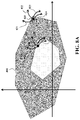
- FIG. 8 A is a schematic of an example of a two-dimensional projection of the control-invariant subset of states defined by various constraints on the operation of the pneumatic brake, according to some embodiments.
- FIG. 8 B is a schematic showing the relation between the feasible region of the states of the machine and control invariant subsets determined according to some embodiments.
- FIG. 9 A shows simulations of the pneumatic brake system without the RG which produces undesirable cycling.
- FIG. 9 B shows simulations of the pneumatic brake system with the RG showing elimination of the cycling, according to some embodiments.
- FIG. 10 A shows simulations of the pneumatic brake system without the RG resulting in overshooting and cycling caused by aggressive integral-action.
- FIG. 10 B shows simulations of the pneumatic brake system with the RG showing inherent anti-windup, according to some embodiments.
- FIG. 11 shows a schematic of a railway vehicle using the control system of FIG. 2 A to prevent the wheel-slip in a train, according to some embodiments.
- the terms “for example,” “for instance,” and “such as,” and the verbs “comprising,” “having,” “including,” and their other verb forms, when used in conjunction with a listing of one or more components or other items, are each to be construed as open ended, meaning that that the listing is not to be considered as excluding other, additional components or items.
- the term “based on” may mean at least partially based on. Further, it is to be understood that the phraseology and terminology employed herein are for the purpose of the description and should not be regarded as limiting. Any heading utilized within this description is for convenience only and has no legal or limiting effect.
- FIG. 1 shows schematic overview of some principles used by some embodiments to prevent wheel-slip in a railway vehicle with a pneumatic brake.
- Some embodiments are based on recognition that the objective of the pneumatic brake is to decelerate or stop a vehicle.
- the vehicle may be a car, bike, bus, or the railway vehicle.
- wheel-slip which is undesirable in excess, occurs when braking force applied to a wheel exceeds traction available to that wheel.
- some embodiments are based on objective of regulating the wheel-slip.
- ‘wheel-slip’ and ‘slip’ may be used interchangeably and would mean the same.
- a speed sensor is provided to each wheel to measure speed of each wheel and an ECU constantly monitors the speed of each wheel. If the ECU detects that the speed of a wheel is slower than speed of the vehicle, a condition indicative of impending wheel lock, valves are actuated to reduce brake pressure at the affected wheel. Thus, reducing the brake pressure on the affected wheel makes the affected wheel to turn faster. Conversely, in some embodiments, if the ECU detects that the speed of a wheel is greater than the speed of other wheels or the vehicle speed, the brake pressure to the wheel is increased so the brake pressure is reapplied, slowing down the wheel. Some embodiments are based on a realization that a control objective is to track a reference acceleration or deceleration. In some embodiments, the wheel-slip is regulated to a deceleration reference.
- Some embodiments are based on recognition that in some situations slip can be beneficial.
- automotive wheel-slip regulating systems such as traction control and anti-lock braking (ABS)
- ABS traction control and anti-lock braking
- the slip is regulated or control to some ratio, e.g., to 0.1 slip ratio. This is because one of the requirements of car break design is to stop or decelerate the car as fast as possible, so that the car can be operated even by less experienced drivers in challenging environments.
- the car break design if applied to the railway vehicles can cause chattering, i.e., periodic breaking.
- the railway vehicles have different dynamics than road vehicles, such as cars, motorcycles, trucks, and buses. For instance, friction between a steel wheel and rail is lower and includes different characteristics than friction between a rubber tire and asphalt.
- the pneumatic brakes used on many trains have unique control design challenges due to their slow dynamics and non-linear hysteresis. To that end, some embodiments are based on recognition that the railway vehicles have different dynamics than the road vehicles and the car break design are not compatible with pneumatic brakes of the railway vehicles.
- a block diagram of a closed-loop pneumatic brake for railway vehicle 100 includes a controller 104 , brake system 106 , and railway vehicle 108 .
- Braking torque ⁇ (t) is produced when brake-block comes into contact with wheel of the railway vehicle.
- a contact force is controlled by pressure p(t) in the brake-cylinder.
- the brake-cylinder is filled from a reservoir which can be kept at a fixed pressure p.
- the pressure p (t) in the brake-cylinder is regulated by controller 104 that modulates the valve opening to achieve a specified pressure.
- the block diagram 100 refers to a closed-loop pneumatic brake system.
- the controller 104 can be a proportional integral derivative (PID) controller, a proportional integral (PI) controller or a proportional derivative (PD) controller.
- PID proportional integral derivative
- PI proportional integral
- PD proportional derivative
- the specified pressure u (t) is determined by the controller 104 .
- the WSP vents gas from the brake cylinder to rapidly reduce braking torque such that the reference deceleration is reached.
- such systems produce a limit cycle, which causes vibrations and excessive jerk that reduces passenger comfort and increases wear on brake mechanism of the pneumatic-brakes.
- some embodiments are based on realization that there is a need to avoid excessive slip to ensure comfort of the ride, reduce noise and improve stopping accuracy. Some embodiments are based on a realization that the slip is not utilized as a control reference, but as a constraint to avoid the excessive slip. To use the slip as a constraint, there is a need for constraint control, and the pneumatic brake 100 of railway vehicle is not suitable to incorporate the slip as a constraint. Therefore, in some embodiments, the pneumatic brake 100 is augmented with a reference governor.
- a block diagram of the augmented pneumatic brake 102 includes the controller 104 , the brake system 106 , the railway vehicle 108 and reference governor (RG) 110 .
- the RG pre-emptively adjusts the deceleration reference to the controller 104 to prevent excessive wheel slip rather than reacting to incipient slip instability as is the case for the WSP system. Since the pneumatic brake 100 is augmented with the RG 110 , rather than replacing the entire the pneumatic brake, the tested and tuned controller 104 of the pneumatic brake 100 is not squandered. Instead, the RG 110 retains the performance of the controller 104 , but adds a feature i.e. enforcing the wheel-slip constraint.
- the reference governor 110 can be used with offline computations to reduce the aforementioned expenses. To that end, some embodiments are based on a realization that the reference governor precomputes an invariant set of combination of values of state variables of the pneumatic brake and the deceleration reference.
- the state variables of the pneumatic brake include the braking torque to a wheel of the railway vehicle and a slip of the wheel. In some embodiments, the state variables of the pneumatic brake include the braking torque to a wheel of the railway vehicle, pressure in the brake-cylinder of the pneumatic brake, and a slip of the wheel.
- the reference governor (RG) 110 provides executable instructions for modifying the deceleration reference upon its violation of wheel-slip constraint.
- the wheel-slip constraint maintains the slip s(t k ) ⁇ s max below a prescribed maximum slip s max .
- the maximum slip s max can be determined from a variety of sources for instance based on known friction characteristics of the wheel/rail or based on a customer requirement.
- the invariant set is a constraint admissible positive invariant (PI) set of values of the state variables of the pneumatic brake and the deceleration reference for which the wheel-slip is maintained below a prescribed level at the current time and for all future times.
- PI positive invariant
- the invariant set is also referred to as set of admissible references.
- the invariant set is referred to as the PI set.
- some embodiments are based on recognition that the reference governor 110 predicts future violation of the wheel-slip constraint when current values of the state variables of the pneumatic brake and the deceleration reference are outside of the invariant set. Further, the reference governor 110 modifies the current value of the deceleration reference outside of the invariant set to its closest value inside the invariant set and controlled with the corresponding modified deceleration reference from the invariant set. Such a control will prevent the slip not only in immediate but even in a distant future.
- the reference governor modifies the current deceleration reference to its closest value from the invariant set to prevent the excessive slip.
- FIG. 2 A shows a block diagram of a control system for the wheel-slip prevention in the railway vehicle with the pneumatic brake, according to some embodiments.
- the control system 200 includes an input interface 202 and an output interface 224 for connecting the control system 200 with other systems and devices.
- the control system 200 may include a plurality of input interfaces and a plurality of output interfaces.
- the input interface 202 is configured to accept a deceleration reference for controlling the pneumatic brake.
- the input interface 202 includes a network interface controller (NIC) 214 adapted to connect the control system 200 through a bus 212 to a network 216 . Through the network 216 , either wirelessly or through wires, the control system 200 receives the deceleration reference 218 .
- NIC network interface controller
- the deceleration reference is generated in response to actions of a railway operator.
- the deceleration reference is received, from a train operator, when the train operator applies brake.
- the deceleration reference is received from a high level controller integrated for instance for autonomous railway vehicles.
- the deceleration reference can be a reference trajectory.
- the control system 200 further includes a processor 204 and a memory 206 that stores instructions that are executable by the processor 204 .
- the processor 204 may be a single core processor, a multi-core processor, a computing cluster, or may comprise any number of other configurations.
- the memory 206 may include random access memory (RAM), read only memory (ROM), flash memory, or any other suitable memory system.
- the processor 204 is connected through the bus 212 to one or more input and output devices.
- the stored instructions implement a method for preventing wheel-slip in the railway vehicle with the pneumatic brake.
- the memory 206 is also configured to store a reference governor 208 providing executable instructions for modifying the deceleration reference upon its violation of the wheel-slip constraint.
- the wheel-slip constraint is a function of state variables of the pneumatic brake.
- the state variables of the state of the pneumatic brake include the braking torque to a wheel of the railway vehicle, pressure in the brake-cylinder of the pneumatic brake, and the slip of the wheel.
- the processor 204 is configured to execute the reference governor 208 to modify the deceleration reference such that the wheel-slip is prevented.
- the pressure in the brake-cylinder of the pneumatic brake is proportional to operation of brake lever by the railway operator.
- the braking torque is a feed forward element for the operation of the railway vehicle.
- the slip of the wheel is used as feedback for operation of the pneumatic brake. Further, the slip can be used to determine the influence of the slip in decelerating or stopping the railway vehicle. The substantial variation of the braking torque under the synergistic influence of the pressure in the brake-cylinder and the slip of the wheel considerably defines the braking operation and performance.
- some embodiments are based on recognition that the combination of values of the aforementioned state variables and the deceleration reference can be utilized, by the control system 200 , for the wheel-slip prevention in the railway vehicle.
- the memory 206 is further configured to store an invariant set 210 of a combination of values of the state variables of the pneumatic brake and the deceleration references.
- FIG. 2 B shows an exemplary invariant set 210 stored in the memory 206 of the control system 200 , according to some embodiments.
- the exemplar invariant set 210 is multi-dimensional and is defined by four parameters i.e. braking torque to the wheel of the railway vehicle ⁇ B , pressure in the brake-cylinder of the pneumatic brake P, the slip of the wheel S and the deceleration difference DR.
- the invariant set 210 includes different sets; each set defined by combination of the respective aforementioned parameters.
- the set 1 of invariant set 210 is defined by the combination of the braking torque to the wheel of the railway vehicle ⁇ B1 , pressure in the brake-cylinder P 1 , the slip of the wheel S 1 and the deceleration difference DR 1 .
- the invariant set 210 may include n-sets and each set defined by the combination of respective aforementioned parameters.
- the invariant set 210 is a constraint admissible positive invariant set of values of the state variables of the pneumatic brake and the deceleration reference for which the wheel-slip is maintained below a prescribed level.
- some embodiments are based on a realization that if the pneumatic brake is operated such that the state variables of the pneumatic brake and the deceleration reference lie inside the invariant set 210 , then wheel-slip can be prevented.
- Some other embodiments are based on a realization that if a current deceleration reference lies inside the invariant set 210 , then wheel-slip can be prevented.
- the reference governor 208 predicts the future violation of the wheel-slip constraint when current values of the state variables of the pneumatic brake and the deceleration reference are outside of the invariant set 210 .
- the processor 204 is configured to execute the reference governor 208 to modify the deceleration reference.
- the reference governor 208 modifies the current value of the deceleration reference outside of the invariant set 210 with its closest value inside the invariant set 210 .
- the invariant set 210 is determined using a backward reachable method that iteratively determines the invariant set 210 , starting from a current set of feasible states of the pneumatic brake and the deceleration reference.
- the memory 206 is further configured to store a controller 228 providing executable instructions for mapping the modified deceleration reference to a sequence of control commands to control the pneumatic brake.
- the processor 204 is configured to execute the controller 228 to map the modified deceleration reference to the sequence of control commands. 17.
- a control command is determined for a control step, such that the sequence of control commands is determined for a sequence of control steps.
- the embodiments execute the reference governor for each of the control steps to adapt the control of the brake to changes of the slip even after the slip has been detected, i.e., after wheel-slip constraint is violated.
- the output interface 224 is configured to output the sequence of control commands to control a pneumatic brake 226 .
- the controlling of the pneumatic brake 226 based on the sequence of control commands includes controlling of parameters of the pneumatic brake such as pressure applied by the brake, pressure inside the brake-cylinder, braking torque, valve opening or closing and the like.
- the system 200 may also be connected to a control interface 220 adapted to connect the control system 200 to actuators 222 of the pneumatic brake system. Through the control interface 220 , the control system 200 is configured to control the actuators 222 of the pneumatic brake system based on the sequence of control commands.
- FIG. 3 A shows a schematic of a pneumatic brake system, according to some embodiments.
- the control system 100 is integrated with the pneumatic brake system.
- the pneumatic brake system comprises a reservoir 300 storing compressed air, a brake-cylinder 302 , a valve 304 and brake pad 306 .
- the brake-cylinder 302 is filled from the reservoir 300 to apply a braking torque to a wheel 308 of the railway vehicle in proportion to pressure p (t) in the brake cylinder 302 .
- the valve 304 is arranged between the reservoir 300 and the brake-cylinder 302 to regulate the pressure p (t) in the brake-cylinder in accordance with the sequence of control commands.
- the pressure p (t) in the brake-cylinder is regulated by an integrated controller that modulates the valve opening to achieve a specified pressure.
- This figure does not show a feature of the invention. Instead this plot is included to demonstrate hysteresis which is an important feature of the pneumatic brake that the invention must consider. Nominally, increasing ⁇ dot over (p) ⁇ (t>0 the brake-cylinder pressure p(t) increases ⁇ dot over ( ⁇ ) ⁇ (t)>0 the brake torque ⁇ (t). Decreasing the pressure ⁇ dot over (p) ⁇ (t) ⁇ 0 decreases torque ⁇ dot over ( ⁇ ) ⁇ (t) ⁇ 0.
- FIG. 3 C depicts the brake torque as a function of the brake-cylinder pressure. Again, this figure is included to demonstrate the hysteresis behavior of the brake which the invention must consider.
- the gains ⁇ and ⁇ describe how changes in the brake-cylinder pressure ⁇ dot over (p) ⁇ (t) affect change in the braking torque ⁇ dot over ( ⁇ ) ⁇ (t) when the braking-cylinder is being filled ⁇ dot over (p) ⁇ (t) ⁇ 0 and emptied ⁇ dot over (p) ⁇ (t) ⁇ 0, respectively.
- Some embodiments consider the brake hysteresis since it delays switching between squeezing and releasing the brake. Hysteresis can cause problems with other control schemes. For instance, a standard linear controller may start filling the brake cylinder, but due to the delay caused by hysteresis this does not cause an immediate response in the braking torque (and thus train speed). So, the controller may over fill the brake-cylinder before the brake responds resulting in too much braking torque and therefore excessive wheel-slip once the delay due to hysteresis ends. Then, the controller must empty the brake-cylinder, but again due to the delay caused by hysteresis the controller will empty the brake-cylinder requiring the controller to refill the cylinder.
- the brake controller (i.e. controller 104 ) includes two modes, namely, reference tracking and slip protection.
- the linear controller (3a & 3b) is dynamic since it includes integral-action for offset-free steady-state tracking for e.g. a proportional-integral controller is typically used.
- the controller is observer-based and, consequently, the linear controller (3a & 3b) includes the observer dynamics.
- slip-speed s(t) enters an unstable-slip region s(t)> s
- the brake controller enters into the slip protection mode where the control objective is to return the slip-speed to a stable-slip region. This is accomplished by venting the brake-cylinder pressure p(t) which eventually reduces brake torque ⁇ (t) allowing the slip-speed s(t) to re-enter the stable-slip region s(t) ⁇ s .
- the control objectives in the two modes i.e. the reference tracking and slip protection, results the limit cycle where the brake-cylinder pressure is alternatingly increased to produce the desired braking torque and vented to halt excessive slip.
- This limit cycle causes vibrations, reducing the passenger comfort and wear on the brake mechanism. Therefore, to overcome the aforementioned undesired effects, a wheel-slip prevention system which pre-emptively modifies the deceleration reference r(t) is provided.
- the deceleration reference r(t) is modified such that the closed-loop pneumatic brake system 100 satisfies output constraints:
- the reference governor (RG) 208 is designed to provide executable instructions for modifying the deceleration reference r(t) upon its violation of the wheel-slip constraint.
- the RG is executed by the processor 204 .
- the violation of the wheel-slip constraint corresponds to the slip-speed entering into the unstable-slip region.
- the violation of the wheel-slip constraint corresponds to the deceleration reference lying outside the invariant set.
- the violation of the wheel-slip constraint refers to the closed-loop pneumatic brake system 100 not satisfying the output constraints (4).
- FIG. 4 shows a schematic of workflow of the reference governor (RG), according to some embodiments.
- the reference governor checks for violation of the wheel-slip constraint 402 . If there is no violation of the wheel-slip constraint, then it implies that the wheel-slip constraint is satisfied. Therefore, no modification to the deceleration reference r(t) 404 is made.
- the RG modifies the deceleration reference r(t) 406 such that the wheel-slip constraint is satisfied 408 .
- the objective of the RG is to prevent the slip-speed s(t k ) from leaving the stable-slip region s(t k ) ⁇ s .
- the RG takes the form of a state-dependent non-convex optimization problem as defined below:
- r ⁇ ( t k ) arg min r ⁇ " ⁇ [LeftBracketingBar]" r - r ⁇ ( t ) ⁇ " ⁇ [RightBracketingBar]” 5 ⁇ a such ⁇ that ⁇ ⁇ r ⁇ R ⁇ ( x ⁇ ( t k ) ) 5 ⁇ b which minimizes (5a) the difference
- between requested r 0 (t k ) and implemented r(t k ) r* deceleration references subject to the implemented reference r contained (5b) in a state-dependent set of admissible references (x).
- the reference governor modifies the deceleration reference outside of the invariant set with its closest value inside the invariant set to satisfy the wheel-slip constraint.
- the brake-hysteresis (2) is modeled in the discrete-time by:
- the equation (6a) only approximates the continuous-time hysteresis (2) since a mode (squeeze, release, hold) transition occurs between sample instances k ⁇ t, (k+1) ⁇ t rather than at an exact sample instance k ⁇ t. Therefore, the brake torque ⁇ (t k ) equals to the sum of torques for each mode weighted by fraction of time spend in that mode. Since the sample-time rate is fast ⁇ t relative to the system dynamics and torque varies continuously with the brake-cylinder pressure, the approximation (6a) is valid.
- some embodiments are based on a realization that instead of considering an individual adhesion-curve, a set that covers all the possible adhesion-curves in the stable-slip region are considered to reduce the nonlinearity and uncertainty in the slip dynamics.
- FIG. 5 shows a cone 500 covering possible adhesion-curves inside a stable-slip region, according to some embodiments.
- the slip-dynamics can then be bounded by differential inclusion:
- the discrete-time dynamics (6a & 6b) are combined into a single PWA system with polyhedral constraints and parametric uncertainty as given below
- the regions Y i ⁇ 4 that determine where each mode (squeeze, release, hold) is active are subsets of output-space 4 where the output of the closed-loop pneumatic brake system includes the brake controller input u(t k ).
- FIG. 6 shows projection of squeeze, release and hold regions in the pressure-torque-input space, according to some embodiments.
- the regions Y i are projected onto the pressure-torque-input space [p(t k ), ⁇ (t k ⁇ 1 ), u(t k )] are shown in in FIG. 6 .
- the slip s(t k ) is exempted in FIG. 6 as the regions Y i only includes simple bounds on the slip s(t) and do not have any constraints that couple slip with the other states or the input.
- the sets Y i are prismatic in the slip s(t k ) direction.
- the brake-cylinder pressure and the brake torque relationship for the squeeze region Y 1 ⁇ Y is the same as described above with reference to FIG. 3 C .
- Some embodiments are based on a recognition that squeeze region Y 1 600 includes additional constraint p(t k ) ⁇ u(t k ) requiring that the pressure p(t k ) is not being vented.
- release region Y 2 602 includes constraint that the brake-cylinder p(t k ) ⁇ u(t k ) is not being filled.
- the hold region is defined as states not in the squeeze region Y 1 600 or the release region Y 2 602 .
- the parameters are
- ⁇ 0 ⁇ circumflex over (X) ⁇ (9a)
- ⁇ k+1 ⁇ ⁇ 0,1 ⁇ ⁇ circumflex over (f) ⁇ ⁇ ⁇ 1 ( ⁇ k ) ⁇ ⁇ circumflex over (X) ⁇ (9b)
- ⁇ circumflex over (X) ⁇ ⁇ circumflex over (x) ⁇ :
- Cx+Dr+d ⁇ Y ⁇ is the set of augmented states z corresponding to outputs y that satisfy the constraints (4).
- the maximal constraint admissible PI set lim k ⁇ ⁇ k is the limit of the iteration (9a & 9b).
- the iteration (9a & 9b) is complicated as the augmented brake dynamics (8) are nonlinear.
- the PWA dynamics and polyhedral constraints of the hybrid model (8) mean that the non-convex backward-reachable sets ⁇ k can be expressed as a union of convex polyhedrons.
- ⁇ 0 ⁇ j ⁇ j k (11)
- ⁇ j k ⁇ circumflex over (x) ⁇ :H j ⁇ circumflex over (x) ⁇ h j ⁇ is the j-th convex polyhedron defining the union ⁇ k .
- the new component sets ⁇ k+1 j of ⁇ k+1 are polytopes given by
- FIG. 7 A is a block diagram of a backward-reachable set computation for determining the invariant set, according to some embodiments.
- the backward-reachable set computation determines a robust invariant subset x and also the invariant set u (x), which determines for any x within x the set of inputs u in that can be applied so that all possible next states are inside x
- the backward-reachable set computation initializes 700 a current set c to a feasible set and determines a previous set of states p 702 as a subset of the current set c such that for all states x in p there exists an input u in such that for all the possible values of the parameters p in P, the updated state is in the current set c .
- the previous set also referred to as a backward reachable set.
- the previous set p is empty 704 , correct operation of the controller cannot be guaranteed, and is further subjected to reconfiguration 706 which implies that the set P of possible values of the parameters should be reduced in size by changing the design or objective of the operation of the brake system. If the current set and the previous set are equal 708 , that is the invariant set 710 otherwise, the previous set is assigned to be the current set 712 and the computation iterates 714 again.
- the iterations 714 are performed until a termination condition is met.
- the termination condition specifies that a difference between the backward-reachable set and the current set is below a threshold.
- the last computed set of state-input couples is the robust admissible input set u (x) for all x within x .
- FIG. 7 B is a block diagram of an exemplar implementation of determining the previous set of states 702 according to one embodiment.
- the embodiment computes the state-input couple that generates an updated state that is in the current set for all the values of the parameters 702 a , and projects 702 b the state input couples into state values, i.e., the embodiment identifies the states that belong to at least one of such state-input couples.
- step 701 a When the stopping constraints are defined by the constraints in Equation (4), the computations of step 701 a can be further simplified.
- the sets and are described by linear inequalities, and a set of linear models described by matrices A i , B i , i 1, . . .
- FIG. 8 A is a schematic of an example of a two-dimensional projection of the invariant set of states defined by various constraints on the operation of the pneumatic brake system, according to some embodiments.
- a feasible region is a multi-dimensional polytope determined by hyperplanes, which are represented by linear inequalities, along multiple dimensions corresponding to the constraints on the operation.
- the values of the state variables of the pneumatic brake and the deceleration reference can be optimal and feasible for one iteration, but all control actions 821 - 824 that the brake controller is allowed to take during the next iteration, can bring a state 820 or the state variables of the pneumatic brake outside of the feasible region 800 .
- Some embodiments are based on a realization that it is possible to select a invariant set 810 of the feasible region, such that from any values of the state variables of the pneumatic brake within the invariant set 810 , there is a control input maintaining the state variables within the invariant set for the known future state variables values of the pneumatic brake and the deceleration reference.
- a control input 834 that maintains the state variables values within the invariant set 810 .
- FIG. 8 B is a schematic showing the relation between a feasible region 802 and an invariant set 804 determined according to some embodiments.
- the invariant set 804 is reduced to form control invariant set 806 , which is less than the invariant set 804 , but has a simpler shape formed by linear equations.
- the shape of the invariant set 804 can be non-convex.
- computation of 806 is simpler, more efficient and advantageous for control purposes.
- FIG. 9 A shows simulations of the pneumatic brake system without the RG which produces undesirable cycling, according to some embodiments.
- the wheel-slip s(t) exceeds the stable-slip threshold s(t)>0.1 causing the brake controller to enter the slip protection mode which produces the undesirable oscillatory behavior as shown in FIG. 9 A .
- the brake-cylinder pressure p(t) is quickly vented to reduce brake torque ⁇ (t) and restore the slip s(t) to the stable-slip region s(t) 0.1. This results in increased deceleration tracking error e(t).
- the tracking controller requires approximately 100 milliseconds to overcome the brake hysteresis and then another approximately 400 milliseconds to achieve the previous deceleration peak, at which point the wheel-slip s(t) again exceeds the threshold s(t)>0.1 and the slip protection mode is again engaged.
- the resulting limit cycle instigates relatively large average deceleration tracking error.
- FIG. 9 B shows simulations of the pneumatic brake system with the RG showing elimination of the cycling, according to some embodiments.
- FIGS. 9 A and 9 B correspond to simulation results with an infeasible deceleration reference without using the RG and with using RG, respectively.
- Some embodiments are based on a realization that a small improvement in deceleration tracking can lead to a significant improvement in stopping accuracy as position error is proportional to double-integral of deceleration error. For example, over a 30 seconds braking maneuver, the RG improves the stopping accuracy by 1.62 meters. Additionally, smoother deceleration profile ( FIG. 9 B ) is produced by the RG which results less jerk than the slip protection mode or WSP system ( FIG. 9 A ), resulting in a comfortable ride for the passengers and reduced wear on the braking mechanism.
- FIG. 10 A shows simulations of the pneumatic brake system without the RG which results in overshooting and cycling caused by aggressive integral-action, according to some embodiments.
- the aggressiveness of the proportional-integral controller is fundamentally limited by the brake hysteresis and adhesion-curve nonlinearity.
- aggressive integral-action can cause overshoot and windup. Both of these issues are aggravated by plant nonlinearity.
- the overshoot can cause the slip-speed to enter the unstable-slip region even when the steady-state deceleration set-point is feasible.
- a delay is caused by the hysteresis, namely, hysteresis delay.
- the hysteresis delay implies that the closed-loop brake system 100 should include a large phase margin which limits the aggressiveness of the tracking controller.
- the closed-loop response of the braking system to a feasible deceleration command is depicted in the FIG. 10 A .
- the more aggressive controller settles approximately three times faster than the previous controller shown in FIGS. 9 A and 9 B . Since each oscillation needs to pass through the hold zone ( FIGS. 3 B & 3 C ), the oscillations produced by the integral-action prevent even faster convergence.
- the closed-loop response shown in FIG. 10 A includes a small overshoot which can pose as a problem near the boundary of the stable-slip region. The RG mitigates these issues allowing use of the more aggressive controller.
- FIG. 10 B shows simulations of the pneumatic brake system with the RG showing inherent anti-windup, according to some embodiments.
- the closed-loop response of the braking system with RG to a deceleration command on the boundary of the stable-slip region is shown in FIG. 10 B .
- the RG decreases the reference r(t). This unwinds the integrator in the brake controller and, consequently, the slip-speed remains in the stable region.
- the oscillations are substantially attenuated allowing the deceleration to converge more quickly to the deceleration reference.
- the RG essentially produces non-linear integral-action that includes beneficial properties, such as fast transient response and offset-free tracking without the disadvantage of poor robustness to model uncertainty and the delays.
- FIG. 11 shows a schematic of a train system using the control system 200 according to some embodiments to prevent the wheel-slip in a train 1100 moving on the railroad track 1104 along the direction 1102 .
- the train 1100 includes pneumatic brake system (not shown in figure) to decelerate or stop the train.
- the control system 200 is integrated with the pneumatic brake system. Whenever brake is applied causing excessive slip, the control system encompasses the reference governor that prevents the excessive slip by modifying the deceleration reference. Further, since the control system 200 eliminates the excessive slip, jerks instigated by the applied brake are eliminated as well. This results in smooth deceleration or stopping which further enhances the passengers ride comfort while the brake is applied.
- Some embodiments are based on recognition that the concept of invariant sets can be used to improve stopping accuracy of the train. It is challenging to consider dynamics of the brake dynamics due to the vast differences in spatial (kilometers vs. micrometers) and temporal (minutes vs. milliseconds) scales. Nonetheless, some implementations of embodiments merge the invariant sets determined for accurate stopping and for breaking to compute a single multi-purpose invariant set.
- individual embodiments may be described as a process which is depicted as a flowchart, a flow diagram, a data flow diagram, a structure diagram, or a block diagram. Although a flowchart may describe the operations as a sequential process, many of the operations can be performed in parallel or concurrently. In addition, the order of the operations may be re-arranged. A process may be terminated when its operations are completed, but may have additional steps not discussed or included in a figure. Furthermore, not all operations in any particularly described process may occur in all embodiments.
- a process may correspond to a method, a function, a procedure, a subroutine, a subprogram, etc. When a process corresponds to a function, the function's termination can correspond to a return of the function to the calling function or the main function.
- embodiments of the subject matter disclosed may be implemented, at least in part, either manually or automatically.
- Manual or automatic implementations may be executed, or at least assisted, through the use of machines, hardware, software, firmware, middleware, microcode, hardware description languages, or any combination thereof.
- the program code or code segments to perform the necessary tasks may be stored in a machine readable medium.
- a processor(s) may perform the necessary tasks.
- Various methods or processes outlined herein may be coded as software that is executable on one or more processors that employ any one of a variety of operating systems or platforms. Additionally, such software may be written using any of a number of suitable programming languages and/or programming or scripting tools, and also may be compiled as executable machine language code or intermediate code that is executed on a framework or virtual machine. Typically, the functionality of the program modules may be combined or distributed as desired in various embodiments.
- Embodiments of the present disclosure may be embodied as a method, of which an example has been provided.
- the acts performed as part of the method may be ordered in any suitable way. Accordingly, embodiments may be constructed in which acts are performed in an order different than illustrated, which may include performing some acts concurrently, even though shown as sequential acts in illustrative embodiments.
Landscapes
- Engineering & Computer Science (AREA)
- Mechanical Engineering (AREA)
- Transportation (AREA)
- Chemical & Material Sciences (AREA)
- Combustion & Propulsion (AREA)
- Regulating Braking Force (AREA)
- Braking Systems And Boosters (AREA)
Abstract
Description

p(t)=C p x p(t)+D p u(t) (1b)
where the dynamics (1a & 1b) have unit dc-gain C (I−A)−1Bp+Dp=1 since the brake-cylinder pressure p(t) asymptotically tracks reference pressure u (t). Other embodiments of the invention can be applied to nonlinear brake models or model with non-unit dc-gain. The brake-cylinder pressure cannot be lower than ambient pressure p=0. Further, the brake-cylinder pressure cannot be higher than the reservoir pressure. Thereby, control input or the reference pressure u(t) cannot command a pressure outside a range of admissible pressures
0≤p(t)≤
0≤u(t)≤
{dot over (x)} u(t)=A u x u(t)+B u e(t) (3a)
u(t)=C u x u(t)+D u e(t) (3b)
where the tracking error e(t)={dot over (v)}(t)−r(t) is the difference between actual {dot over (v)}(t) and desired r(t) deceleration reference r(t) and the output of the controller (3a & 3b) is set-point u(t) of the brake-cylinder pressure. The linear controller (3a & 3b) is dynamic since it includes integral-action for offset-free steady-state tracking for e.g. a proportional-integral controller is typically used. In some embodiments, the controller is observer-based and, consequently, the linear controller (3a & 3b) includes the observer dynamics.
which minimizes (5a) the difference |r−r0(tk)| between requested r0(tk) and implemented r(tk)=r* deceleration references subject to the implemented reference r contained (5b) in a state-dependent set of admissible references


Piecewise Affine (PWA) of the Closed-Loop Brake System
where p=p(tk) and τ−=τ(tk−1) are current break-cylinder pressure and previous brake-torque, respectively, at the k-th sample-time tk=kΔt. In some embodiments, the equation (6a) only approximates the continuous-time hysteresis (2) since a mode (squeeze, release, hold) transition occurs between sample instances kΔt, (k+1)Δt rather than at an exact sample instance kΔt. Therefore, the brake torque τ (tk) equals to the sum of torques for each mode weighted by fraction of time spend in that mode. Since the sample-time rate is fast Δt relative to the system dynamics and torque varies continuously with the brake-cylinder pressure, the approximation (6a) is valid.
Further, the constraint {dot over (p)}(t)≥0 from (2) requiring that the brake cylinder is not filled in the release region replaced with the equivalent constraint u(tk)≤p(tk).
s(t k+1)=a s(ξ)s(t k)+b s(ξ)τ(t k) (6b)
where s(tk) and τ (tk) are the slip s(t) and brake-torque τ (t) sampled at the k-th sample-time tk=kΔt. The uncertain model parameters as(ξ) and bs(ξ) are given by convex combinations as(ξ)=ξa s+(1−ξ)ās and bs(ξ)=ξb s+(1ξ)
where the state x(tk)=[xu(tk), xp(tk), τ (tk−1), s(tk)] is comprised of the current states of the controller xu(tk) and the brake-cylinder pressure xp (tk), the previous brake torque τ (tk−1), and the current wheel-slip s(tk). The constrained outputs y(tk)=[u(tk), p(tk), τ (tk−1), s(tk)]T are the current control input u(tk), current brake-cylinder pressure p(tk), the previous brake torque τ (tk−1), and the current wheel-slip s(tk). The three modes of the hybrid system (7a & 7b) are the squeeze mode i=1, release mode i=2, and hold mode i=3. The regions Yi⊂


Y 3 ={x:
Set of Admissible References
where the augmented state {circumflex over (x)} (tk)=[x(tk), r(tk)]T∈


for i=1; 2; 3. Further, the PI set is computed using the approach of iteratively backward propagating the system constraints (4) through the system dynamics (8).
Ω0 ={circumflex over (X)} (9a)
Ωk+1=∩ξ∈{0,1} {circumflex over (f)} ξ −1(Ωk)∩{circumflex over (X)} (9b)
where {circumflex over (f)}ξ −1 is pre-image of the augmented dynamics (8) for ξ=0, 1 and {circumflex over (X)}={{circumflex over (x)}: Cx+Dr+d∈Y} is the set of augmented states z corresponding to outputs y that satisfy the constraints (4). The maximal constraint admissible PI set

Ω0=∪jΩj k (11)
where Ωj k={{circumflex over (x)}:Hj{circumflex over (x)}≤hj} is the j-th convex polyhedron defining the union Ωk. The backward propagation (9a & 9b) can thus be implemented by computing the pre-image of each component Ωj k of the set Ωk under each mode i=1, 2, 3 of the dynamics (8). The new component sets Ωk+1 j of Ωk+1 are polytopes given by
for j=1, . . . , J and i=1, 2, 3 where Ωj k={{circumflex over (x)}:Hj{circumflex over (x)}≤hj} and {circumflex over (X)}={{circumflex over (x)}:Gi{circumflex over (x)}≤gi}.


f(x,u,p)∈co({A i x(k)+B i u(k)}i=1 l)⊗B w co({w j}j=1 η) (12)
for all p in P, where “co” denotes the convex hull and ⊗ denotes the set sum.
Claims (16)
Priority Applications (3)
| Application Number | Priority Date | Filing Date | Title |
|---|---|---|---|
| US16/737,169 US11584341B2 (en) | 2020-01-08 | 2020-01-08 | System and method for wheel-slip prevention in railway vehicles with pneumatic brakes |
| PCT/JP2020/049305 WO2021140999A1 (en) | 2020-01-08 | 2020-12-24 | System and method for wheel-slip prevention in railway vehicles with pneumatic brakes |
| JP2022561257A JP7341356B2 (en) | 2020-01-08 | 2020-12-24 | System and method for preventing wheel slip on railway vehicles with pneumatic brakes |
Applications Claiming Priority (1)
| Application Number | Priority Date | Filing Date | Title |
|---|---|---|---|
| US16/737,169 US11584341B2 (en) | 2020-01-08 | 2020-01-08 | System and method for wheel-slip prevention in railway vehicles with pneumatic brakes |
Publications (2)
| Publication Number | Publication Date |
|---|---|
| US20210206358A1 US20210206358A1 (en) | 2021-07-08 |
| US11584341B2 true US11584341B2 (en) | 2023-02-21 |
Family
ID=74505318
Family Applications (1)
| Application Number | Title | Priority Date | Filing Date |
|---|---|---|---|
| US16/737,169 Active 2041-03-27 US11584341B2 (en) | 2020-01-08 | 2020-01-08 | System and method for wheel-slip prevention in railway vehicles with pneumatic brakes |
Country Status (3)
| Country | Link |
|---|---|
| US (1) | US11584341B2 (en) |
| JP (1) | JP7341356B2 (en) |
| WO (1) | WO2021140999A1 (en) |
Families Citing this family (3)
| Publication number | Priority date | Publication date | Assignee | Title |
|---|---|---|---|---|
| CN113671826B (en) * | 2021-07-18 | 2023-10-13 | 北京理工大学 | A rapid assessment method for the aerodynamically assisted orbit accessibility of transatmospheric vehicles |
| DE102021210463A1 (en) * | 2021-09-21 | 2023-03-23 | Siemens Mobility GmbH | Method and device for measuring a parameter relevant to the movement of a rail vehicle |
| CN113997987B (en) * | 2021-11-16 | 2024-01-30 | 中国铁道科学研究院集团有限公司 | Train anti-skid control method and device |
Citations (2)
| Publication number | Priority date | Publication date | Assignee | Title |
|---|---|---|---|---|
| US20020088673A1 (en) * | 2001-01-05 | 2002-07-11 | General Electric Company | Railcar anti-skid brakes |
| US20150294049A1 (en) * | 2014-04-14 | 2015-10-15 | Konkuk University Industrial Cooperation Corp. | Brake hils system for a railway vehicle |
Family Cites Families (3)
| Publication number | Priority date | Publication date | Assignee | Title |
|---|---|---|---|---|
| GB442518A (en) * | 1934-07-07 | 1936-02-07 | Knorr Bremse Ag | Improvements in or relating to compressed air brakes |
| US4671576A (en) * | 1985-03-06 | 1987-06-09 | Wabco Westinghouse (Railway Brake) (Pty.) Ltd. | Deceleration control system |
| JP6539455B2 (en) * | 2015-02-10 | 2019-07-03 | ナブテスコ株式会社 | Brake control device and brake control method |
-
2020
- 2020-01-08 US US16/737,169 patent/US11584341B2/en active Active
- 2020-12-24 JP JP2022561257A patent/JP7341356B2/en active Active
- 2020-12-24 WO PCT/JP2020/049305 patent/WO2021140999A1/en not_active Ceased
Patent Citations (2)
| Publication number | Priority date | Publication date | Assignee | Title |
|---|---|---|---|---|
| US20020088673A1 (en) * | 2001-01-05 | 2002-07-11 | General Electric Company | Railcar anti-skid brakes |
| US20150294049A1 (en) * | 2014-04-14 | 2015-10-15 | Konkuk University Industrial Cooperation Corp. | Brake hils system for a railway vehicle |
Also Published As
| Publication number | Publication date |
|---|---|
| JP7341356B2 (en) | 2023-09-08 |
| JP2023506325A (en) | 2023-02-15 |
| US20210206358A1 (en) | 2021-07-08 |
| WO2021140999A1 (en) | 2021-07-15 |
Similar Documents
| Publication | Publication Date | Title |
|---|---|---|
| Tavernini et al. | An explicit nonlinear model predictive ABS controller for electro-hydraulic braking systems | |
| US11584341B2 (en) | System and method for wheel-slip prevention in railway vehicles with pneumatic brakes | |
| KR102786049B1 (en) | Motion control of motor vehicles | |
| Yi et al. | A vehicle control algorithm for stop-and-go cruise control | |
| Guvenc et al. | Robust yaw stability controller design and hardware-in-the-loop testing for a road vehicle | |
| Chen et al. | Hierarchical adaptive path-tracking control for autonomous vehicles | |
| Yang et al. | Quasi-linear optimal path controller applied to post impact vehicle dynamics | |
| CN105102283A (en) | Vehicle brake control device | |
| Ali et al. | Predictive prevention of loss of vehicle control for roadway departure avoidance | |
| Gounis et al. | Intelligent momentary assisted control for autonomous emergency braking | |
| Ivanov | Design and testing of ABS for electric vehicles with individually controlled on-board motor drives | |
| Polack et al. | Finite-time stabilization of longitudinal control for autonomous vehicles via a model-free approach | |
| Chatrath et al. | Vehicle dynamics control using model predictive control allocation combined with an adaptive parameter estimator | |
| Van Koutrik | Optimal control for race car minimum time maneuvering | |
| US12427956B2 (en) | Predictive anti-lag braking control for autonomous driving | |
| Berntorp et al. | Hierarchical predictive control for ground-vehicle maneuvering | |
| Danielson et al. | A reference governor for wheel-slip prevention in railway vehicles with pneumatic brakes | |
| Chatrath | Vehicle dynamics control using control allocation | |
| US12377840B2 (en) | Method for generating a lateral offset trajectory | |
| Rath et al. | Robust lane keeping control in automated vehicles: A driver-in-the loop approach | |
| Hajidavalloo et al. | Model-free vehicle rollover prevention: A data-driven predictive control approach | |
| May et al. | Adaptive Input Reduction for Chassis Control Functions using Model Predictive Control | |
| Ren et al. | Hierarchical Robust Spacing and Speed Control Against Chassis Actuation Perturbations and Unknown Disturbances | |
| Jiang | A novel feedback control approach to a class of antilock brake problems | |
| CN121163915A (en) | Parking track performance test method and system and vehicle |
Legal Events
| Date | Code | Title | Description |
|---|---|---|---|
| FEPP | Fee payment procedure |
Free format text: ENTITY STATUS SET TO UNDISCOUNTED (ORIGINAL EVENT CODE: BIG.); ENTITY STATUS OF PATENT OWNER: LARGE ENTITY |
|
| STPP | Information on status: patent application and granting procedure in general |
Free format text: DOCKETED NEW CASE - READY FOR EXAMINATION |
|
| STPP | Information on status: patent application and granting procedure in general |
Free format text: NON FINAL ACTION MAILED |
|
| STPP | Information on status: patent application and granting procedure in general |
Free format text: RESPONSE TO NON-FINAL OFFICE ACTION ENTERED AND FORWARDED TO EXAMINER |
|
| STPP | Information on status: patent application and granting procedure in general |
Free format text: NOTICE OF ALLOWANCE MAILED -- APPLICATION RECEIVED IN OFFICE OF PUBLICATIONS |
|
| STCF | Information on status: patent grant |
Free format text: PATENTED CASE |
|
| MAFP | Maintenance fee payment |
Free format text: PAYMENT OF MAINTENANCE FEE, 4TH YEAR, LARGE ENTITY (ORIGINAL EVENT CODE: M1551); ENTITY STATUS OF PATENT OWNER: LARGE ENTITY Year of fee payment: 4 |