US11573360B2 - Polarization compensator for tilted surfaces - Google Patents
Polarization compensator for tilted surfaces Download PDFInfo
- Publication number
- US11573360B2 US11573360B2 US16/846,843 US202016846843A US11573360B2 US 11573360 B2 US11573360 B2 US 11573360B2 US 202016846843 A US202016846843 A US 202016846843A US 11573360 B2 US11573360 B2 US 11573360B2
- Authority
- US
- United States
- Prior art keywords
- compensator
- polarized light
- thickness
- optical component
- polarization
- Prior art date
- Legal status (The legal status is an assumption and is not a legal conclusion. Google has not performed a legal analysis and makes no representation as to the accuracy of the status listed.)
- Active, expires
Links
- 230000010287 polarization Effects 0.000 title claims abstract description 64
- 230000003287 optical effect Effects 0.000 claims abstract description 63
- 238000010521 absorption reaction Methods 0.000 claims abstract description 22
- 239000000463 material Substances 0.000 claims abstract description 15
- 239000000758 substrate Substances 0.000 claims abstract description 14
- 230000005540 biological transmission Effects 0.000 claims description 45
- 238000000576 coating method Methods 0.000 claims description 23
- 239000011248 coating agent Substances 0.000 claims description 20
- 239000004973 liquid crystal related substance Substances 0.000 claims description 11
- 230000001419 dependent effect Effects 0.000 claims description 9
- 230000031700 light absorption Effects 0.000 claims description 6
- 239000002086 nanomaterial Substances 0.000 claims description 4
- 210000001747 pupil Anatomy 0.000 claims description 3
- 239000010410 layer Substances 0.000 description 15
- 230000008859 change Effects 0.000 description 11
- 230000000694 effects Effects 0.000 description 10
- 239000002346 layers by function Substances 0.000 description 8
- 238000013461 design Methods 0.000 description 7
- 238000000034 method Methods 0.000 description 5
- 230000008033 biological extinction Effects 0.000 description 4
- 238000003384 imaging method Methods 0.000 description 4
- 238000012937 correction Methods 0.000 description 3
- 238000009826 distribution Methods 0.000 description 3
- 239000011521 glass Substances 0.000 description 3
- 239000013078 crystal Substances 0.000 description 2
- 230000007423 decrease Effects 0.000 description 2
- 239000003989 dielectric material Substances 0.000 description 2
- 238000003780 insertion Methods 0.000 description 2
- 230000037431 insertion Effects 0.000 description 2
- 239000011159 matrix material Substances 0.000 description 2
- 230000007246 mechanism Effects 0.000 description 2
- 239000002184 metal Substances 0.000 description 2
- 229910052751 metal Inorganic materials 0.000 description 2
- 238000012986 modification Methods 0.000 description 2
- 230000004048 modification Effects 0.000 description 2
- 229920000642 polymer Polymers 0.000 description 2
- 238000002310 reflectometry Methods 0.000 description 2
- 239000002356 single layer Substances 0.000 description 2
- 241000282461 Canis lupus Species 0.000 description 1
- 239000004986 Cholesteric liquid crystals (ChLC) Substances 0.000 description 1
- 239000006096 absorbing agent Substances 0.000 description 1
- 239000011358 absorbing material Substances 0.000 description 1
- 230000003190 augmentative effect Effects 0.000 description 1
- 230000009286 beneficial effect Effects 0.000 description 1
- 230000008901 benefit Effects 0.000 description 1
- 238000004364 calculation method Methods 0.000 description 1
- 230000003247 decreasing effect Effects 0.000 description 1
- 238000001514 detection method Methods 0.000 description 1
- 238000006073 displacement reaction Methods 0.000 description 1
- 238000005516 engineering process Methods 0.000 description 1
- 230000001747 exhibiting effect Effects 0.000 description 1
- 238000009501 film coating Methods 0.000 description 1
- 238000002955 isolation Methods 0.000 description 1
- 238000004519 manufacturing process Methods 0.000 description 1
- 150000002739 metals Chemical class 0.000 description 1
- 238000000386 microscopy Methods 0.000 description 1
- 238000005375 photometry Methods 0.000 description 1
- 238000004321 preservation Methods 0.000 description 1
- 230000008569 process Effects 0.000 description 1
- 238000011160 research Methods 0.000 description 1
- 239000004065 semiconductor Substances 0.000 description 1
- 238000001228 spectrum Methods 0.000 description 1
- 239000010409 thin film Substances 0.000 description 1
- 229940070527 tourmaline Drugs 0.000 description 1
- 229910052613 tourmaline Inorganic materials 0.000 description 1
- 239000011032 tourmaline Substances 0.000 description 1
- 230000009466 transformation Effects 0.000 description 1
- 238000000844 transformation Methods 0.000 description 1
Images


Classifications
-
- G—PHYSICS
- G02—OPTICS
- G02F—OPTICAL DEVICES OR ARRANGEMENTS FOR THE CONTROL OF LIGHT BY MODIFICATION OF THE OPTICAL PROPERTIES OF THE MEDIA OF THE ELEMENTS INVOLVED THEREIN; NON-LINEAR OPTICS; FREQUENCY-CHANGING OF LIGHT; OPTICAL LOGIC ELEMENTS; OPTICAL ANALOGUE/DIGITAL CONVERTERS
- G02F1/00—Devices or arrangements for the control of the intensity, colour, phase, polarisation or direction of light arriving from an independent light source, e.g. switching, gating or modulating; Non-linear optics
-
- G—PHYSICS
- G02—OPTICS
- G02B—OPTICAL ELEMENTS, SYSTEMS OR APPARATUS
- G02B5/00—Optical elements other than lenses
- G02B5/30—Polarising elements
- G02B5/3025—Polarisers, i.e. arrangements capable of producing a definite output polarisation state from an unpolarised input state
- G02B5/3066—Polarisers, i.e. arrangements capable of producing a definite output polarisation state from an unpolarised input state involving the reflection of light at a particular angle of incidence, e.g. Brewster's angle
-
- G—PHYSICS
- G02—OPTICS
- G02B—OPTICAL ELEMENTS, SYSTEMS OR APPARATUS
- G02B27/00—Optical systems or apparatus not provided for by any of the groups G02B1/00 - G02B26/00, G02B30/00
- G02B27/28—Optical systems or apparatus not provided for by any of the groups G02B1/00 - G02B26/00, G02B30/00 for polarising
- G02B27/286—Optical systems or apparatus not provided for by any of the groups G02B1/00 - G02B26/00, G02B30/00 for polarising for controlling or changing the state of polarisation, e.g. transforming one polarisation state into another
-
- G—PHYSICS
- G02—OPTICS
- G02F—OPTICAL DEVICES OR ARRANGEMENTS FOR THE CONTROL OF LIGHT BY MODIFICATION OF THE OPTICAL PROPERTIES OF THE MEDIA OF THE ELEMENTS INVOLVED THEREIN; NON-LINEAR OPTICS; FREQUENCY-CHANGING OF LIGHT; OPTICAL LOGIC ELEMENTS; OPTICAL ANALOGUE/DIGITAL CONVERTERS
- G02F1/00—Devices or arrangements for the control of the intensity, colour, phase, polarisation or direction of light arriving from an independent light source, e.g. switching, gating or modulating; Non-linear optics
- G02F1/0009—Materials therefor
- G02F1/0063—Optical properties, e.g. absorption, reflection or birefringence
-
- G—PHYSICS
- G02—OPTICS
- G02F—OPTICAL DEVICES OR ARRANGEMENTS FOR THE CONTROL OF LIGHT BY MODIFICATION OF THE OPTICAL PROPERTIES OF THE MEDIA OF THE ELEMENTS INVOLVED THEREIN; NON-LINEAR OPTICS; FREQUENCY-CHANGING OF LIGHT; OPTICAL LOGIC ELEMENTS; OPTICAL ANALOGUE/DIGITAL CONVERTERS
- G02F1/00—Devices or arrangements for the control of the intensity, colour, phase, polarisation or direction of light arriving from an independent light source, e.g. switching, gating or modulating; Non-linear optics
- G02F1/01—Devices or arrangements for the control of the intensity, colour, phase, polarisation or direction of light arriving from an independent light source, e.g. switching, gating or modulating; Non-linear optics for the control of the intensity, phase, polarisation or colour
- G02F1/13—Devices or arrangements for the control of the intensity, colour, phase, polarisation or direction of light arriving from an independent light source, e.g. switching, gating or modulating; Non-linear optics for the control of the intensity, phase, polarisation or colour based on liquid crystals, e.g. single liquid crystal display cells
- G02F1/133—Constructional arrangements; Operation of liquid crystal cells; Circuit arrangements
- G02F1/1333—Constructional arrangements; Manufacturing methods
- G02F1/1335—Structural association of cells with optical devices, e.g. polarisers or reflectors
- G02F1/13363—Birefringent elements, e.g. for optical compensation
- G02F1/133633—Birefringent elements, e.g. for optical compensation using mesogenic materials
-
- G—PHYSICS
- G02—OPTICS
- G02F—OPTICAL DEVICES OR ARRANGEMENTS FOR THE CONTROL OF LIGHT BY MODIFICATION OF THE OPTICAL PROPERTIES OF THE MEDIA OF THE ELEMENTS INVOLVED THEREIN; NON-LINEAR OPTICS; FREQUENCY-CHANGING OF LIGHT; OPTICAL LOGIC ELEMENTS; OPTICAL ANALOGUE/DIGITAL CONVERTERS
- G02F1/00—Devices or arrangements for the control of the intensity, colour, phase, polarisation or direction of light arriving from an independent light source, e.g. switching, gating or modulating; Non-linear optics
- G02F1/01—Devices or arrangements for the control of the intensity, colour, phase, polarisation or direction of light arriving from an independent light source, e.g. switching, gating or modulating; Non-linear optics for the control of the intensity, phase, polarisation or colour
- G02F1/13—Devices or arrangements for the control of the intensity, colour, phase, polarisation or direction of light arriving from an independent light source, e.g. switching, gating or modulating; Non-linear optics for the control of the intensity, phase, polarisation or colour based on liquid crystals, e.g. single liquid crystal display cells
- G02F1/133—Constructional arrangements; Operation of liquid crystal cells; Circuit arrangements
- G02F1/1333—Constructional arrangements; Manufacturing methods
- G02F1/1337—Surface-induced orientation of the liquid crystal molecules, e.g. by alignment layers
- G02F1/133742—Surface-induced orientation of the liquid crystal molecules, e.g. by alignment layers for homeotropic alignment
-
- G—PHYSICS
- G02—OPTICS
- G02F—OPTICAL DEVICES OR ARRANGEMENTS FOR THE CONTROL OF LIGHT BY MODIFICATION OF THE OPTICAL PROPERTIES OF THE MEDIA OF THE ELEMENTS INVOLVED THEREIN; NON-LINEAR OPTICS; FREQUENCY-CHANGING OF LIGHT; OPTICAL LOGIC ELEMENTS; OPTICAL ANALOGUE/DIGITAL CONVERTERS
- G02F2202/00—Materials and properties
- G02F2202/04—Materials and properties dye
Definitions
- Certain optical systems require precisely controlling the state-of-polarization (SOP) when encountering one or more reflecting or absorbing surfaces contained between the input and output. These surfaces can create a polarization nonuniformity that depends upon ray position and/or orientation in the system. For instance, a plane-wave normally incident on a convex lens may preserve the SOP on axis, but may show an increase in polarization distortion with ray displacement from the axis. A similar result may occur with a point-source incident on a plano surface. In the case of an uncoated isotropic dielectric (e.g. glass), the Fresnel equations give the transmission/reflection of light polarized parallel (P) and perpendicular (S) to the plane of incidence (POI).
- SOP state-of-polarization
- the angle-of-incidence is that between the ray direction and the local surface normal. At zero AOI, the SOP may be preserved, but the extent of polarization distortion typically grows with AOI, affecting the quality of the output.
- AOI angle-of-incidence
- direct-view/projection liquid crystal displays direct-view/projection organic light emitting diode displays
- broad-band polarization-based isolators i.e. pancake-lenses
- accurate polarization control over angle may determine factors such as dynamic-range and contrast. Minute polarization distortions can, in some instances, cause display contrast ratio to plummet when not precisely controlled.
- an optical component comprising an anisotropic material with an optic-axis substantially normal to the substrate, a thickness-direction retardation (R th ), and a thickness-direction absorption.
- the absorption of light at normal incidence may be ⁇ 5% or ⁇ 2%.
- the transmission of p-polarized light may be less than the transmission of s-polarized light and the compensator may produce a phase-difference between transmitted p-polarized light and transmitted s-polarized light.
- the compensator extinction-coefficient and thickness are selected to produce a specific non-zero transmission of p-polarized light at a prescribed angle-of-incidence.
- the optical component may further include a non-absorbing anisotropic material with an optic-axis normal to the substrate and a second thickness-direction retardation, wherein the combined angle-dependent absorption and R th can be selected independently.
- the compensator may include a cross-linked reactive mesogen.
- the compensator may include a homeotropically aligned liquid crystal.
- the compensator may include a guest-host liquid-crystal with an oriented absorbing dye.
- the compensator may include an oriented nano-structure.
- a compensator for use in a polarization-preserving optical-system, comprising an anisotropic material with an optic-axis substantially normal to the substrate, a thickness-direction retardation (R th ), and a thickness-direction absorption, wherein the addition of the compensator substantially increases system contrast or uniformity of a polarization pupil map.
- the absorption of light at normal incidence may be ⁇ 5% or ⁇ 2%.
- the transmission of p-polarized light may be less than the transmission of s-polarized light and wherein the compensator produces a phase-difference between transmitted p-polarized light and transmitted s-polarized light.
- the compensator extinction-coefficient and thickness may be selected to produce a specific non-zero transmission of p-polarized light at a prescribed angle-of-incidence.
- the compensator may further include a non-absorbing anisotropic material with an optic-axis normal to the substrate and a second thickness-direction retardation, wherein the combined angle-dependent absorption and R th can be selected independently.
- the compensator may include a cross-linked reactive mesogen.
- the compensator may include a homeotropically aligned liquid crystal.
- the compensator may include a guest-host liquid-crystal with an oriented absorbing dye.
- the compensator may include an oriented nano-structure.
- an optical system comprising an input polarized light, a lens that produces diattenuation in transmission, and a Z-Partial-Polarizer (ZPP), wherein the ZPP transmits p-polarized light less than s-polarized light in a manner that substantially reduces the polarization distortion produced by diattenuation.
- ZPP Z-Partial-Polarizer
- the system may transmit p-polarized light and s-polarized light equivalently.
- the prescribed incidence-angle may be between 30° and 60°.
- the ZPP may be located in a position of either a converging or diverging cone of light.
- the system may further include a functional coating with a thickness-direction retardation (R th ) and a C-plate co-located with the ZPP that substantially reduces the net R th .
- the system may further include a functional coating with a thickness-direction retardation (R th ) and a ZPP with a thickness-direction retardation such that the net thickness direction retardation is substantially reduced.
- an optical system comprising an input polarizer, an analyzing polarizer, and a functional layer between the polarizers, such that the surface of the functional layer is tilted with respect to at least one ray of incident light, and a Z-Partial-Polarizer (ZPP).
- ZPP Z-Partial-Polarizer
- the functional layer may produce diattenuation for the at least one ray, and the ZPP may substantially compensate for the diattenuation by attenuating p-polarized light more than s-polarized light.
- the functional layer may further produce thickness-direction retardation, and the ZPP may further produce a thickness-direction retardation, such that the net thickness-direction retardation of the system is substantially reduced.
- the functional layer may be a partial-reflector that produces a thickness-direction retardation, and the system may further include a C-plate co-located with the ZPP such that the net thickness-direction retardation of the system is substantially reduced.
- the system may further include a polarization-based triple-pass lens and the functional layer comprises a compound-curved partial-reflector.
- the functional layer may be a partial-reflector that produces a thickness-direction retardation, and the ZPP may produce a thickness-direction retardation such that the net thickness-direction retardation of the system is substantially reduced.
- the functional layer may be a partial-reflector that produces a thickness-direction retardation, and the system may further include a C-plate co-located with the ZPP such that the net thickness-direction retardation of the system is substantially reduced.
- FIG. 1 shows an exemplary optical system for demonstrating the effect of a tilted surface on the SOP.
- FIG. 2 shows the independent contributions of retardation and diattenuation in distorting a circular input polarization.
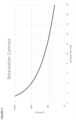
- FIG. 3 shows contrast versus incidence angle for the system of FIG. 1 , with the insertion of a tilted isotropic slab with a refractive index of 1.52.
- FIG. 4 shows the effect of retardation and diattenuation from a partially-reflective coating on a convex lens, as used in a polarization-based triple-pass lens.
- FIG. 5 shows contrast versus retardation for a polarization-based triple-pass lens, where the tilted surface produces only a retardation.
- FIG. 6 shows contrast versus transmission-difference for a polarization-based triple-pass lens, where the tilted surface produces only diattenuation.
- FIG. 7 shows contrast of the system of FIG. 3 with insertion of a z-partial-polarizer (ZPP) to compensate for slab diattenuation.
- ZPP z-partial-polarizer
- FIG. 8 A shows a simple optical system containing a linearly polarized input and a lens, in which diattenuation from the lens distorts the polarization at the output.
- FIG. 8 B shows a simple optical system containing a linearly polarized input and a lens, in which the addition of a Z-partial polarizer (ZPP) restores a uniform linear polarization.
- ZPP Z-partial polarizer
- FIG. 9 A shows a simple optical system containing a circularly polarized input and a lens, in which diattenuation from the lens distorts the polarization at the output.
- FIG. 9 B shows a simple optical system containing a circularly polarized input and a lens, in which the addition of a Z-partial polarizer (ZPP) restores a uniform circular polarization.
- ZPP Z-partial polarizer
- FIG. 10 A shows a simple optical system containing a circularly polarized input and a coated lens with a non-zero R th , in which diattenuation and retardation from the coated lens distort the polarization at the output.
- FIG. 10 B shows a simple optical system containing a circularly polarized input and a coated lens with a non-zero R th , in which the addition of a Z-partial polarizer (ZPP) and C-Plate restore a uniform circular polarization.
- ZPP Z-partial polarizer
- FIG. 11 shows a device using a ZPP to optimize the SOP for a geometric-phase switchable focal-length lens.
- polarization compensators for use with surfaces that are tilted relative to incident light that make it feasible to preserve the SOP over a range of ray angles and/or ray positions in an optical system.
- the compensators can be used in optical systems containing multiple plano surfaces that accommodate a wide range of incidence angles (e.g. converging or diverging light).
- the compensators can also be used in optical systems that are substantially collimated but contain non-plano surfaces, such as refracting elements.
- the system may contain elements of each, such as low f-number polarization-preserving optical systems that contain high-power refracting elements.
- the disclosed techniques may also be used in combination with diffractive optical components, such as geometric-phase lenses, which have circular eigen-polarizations.
- the surfaces may be uncoated dielectrics, multi-layer dielectrics (e.g. reflectors or partial reflectors), absorbing layers (e.g. metals or semi-conductors), or hybrids of these.
- the one or more tilted surfaces may produce a distortion in phase-difference, amplitude-difference, or both, that is compensated using the described structures.
- FIG. 1 shows an example of a transmissive optical system that demonstrates the problem.
- A e.g.
- point light source producing an angular distribution of ray angles (and likely a distribution of wavelengths) is incident on an ideal circular polarizer. That is, the ellipticity of the SOP exiting the CP for each ray and wavelength is unity, where the ellipticity is defined here as the magnitude of the ellipse field-ratio, with the larger of the components in the denominator. Note that this requires zero reflection at the exit face of the first CP and the entrance of the second in order to preserve polarization.
- the ideal orthogonal circular polarization analyzer followed by an optical receiver that collects light from the source over a range of angles.
- the latter may be the eye, a square-law detector, a digital camera, or additional (e.g. relay) optics.
- the circular polarizers generate/analyze the SOP perfectly, such that no light exits the system, and no optical power is incident on the receiver. This may be regarded an optical system with infinite contrast.
- the output can also be expressed as a Jones vector that resolves the SOP parallel/perpendicular to a linear analyzing polarizer. In the air space between the circular polarizers, elements can be inserted that demonstrate the change in ellipticity from a tilted surface and the resulting impact on contrast.
- the vector for the transmission resolved along the exit polarizer can be given by
- the first term in each vector is produced by the change in SOP due to diattenuation, which is the change in polarization introduced by a difference in transmission between P and S polarization.
- FIG. 2 illustrates the SOP between the tilted surface and the analyzing circular polarizer, due to the independent contribution of diattenuation and retardation. As shown, diattenuation causes a change in ellipticity of a circular input with orientation that contains the local POI.
- the second term in each vector is the result of a change in SOP due to retardation, or phase-difference between P and S polarization. Retardation tends to introduce ellipticity with orientation at ⁇ 45° to the POI, as shown in FIG. 2 .
- the leakage term (
- the above vector can also be expressed as a system contrast ratio, or
- T 0 is the average transmission of S and P light.
- a surface represents any change in (complex) refractive index, such as a slab of glass/polymer, a multi-layer coating on a substrate, an evaporated/sputtered metal, etc.
- a tilted dielectric slab in transmission the phase difference is zero, and only diattenuation is present.
- the difference between P and S transmission grows with AOI up to the Brewster angle.
- P transmission in general increases with AOI, while S transmission declines up to the Brewster angle.
- FIG. 3 shows the single-pass contrast of an uncoated (e.g. glass) isotropic slab with a refractive index of 1.52 in air.
- the contrast remains very high above 20°, but falls to 5,000:1 at 27°, 1,000:1 at 38°, 500:1 at 45°, 200:1 at 53°, and 100:1 at 60°.
- the contrast can be substantially independent of the azimuth of the POI.
- the loss in contrast can become more severe when the tilted surface is a multi-layer coating and produces both diattenuation and retardation.
- systems that generate large local surface normal distributions, via the source characteristics and/or the surface profile (e.g. lenses) can exacerbate the problem.
- the local AOI contains a contribution from both the ray angle with respect to the optic-axis, as well as that from the tilt of the lens surface with respect to the optic-axis.
- the tilts have azimuth independence (such as lenses aligned along a common axis), while others may have a large bias angle.
- dichroic splitters that separate bands of wavelengths e.g. for 3-panel RGB projection
- the disclosed techniques permit a suitable compensation for polarization distortion.
- Some coatings can improve the diattenuation by driving both P and S reflectivity to a very low value.
- a multi-layer AR coating may have an increased C-plate retardation, which can represent a tradeoff.
- More complex multi-layer coating designs may be called for in optical systems to achieve a particular set of functional requirements. This may be to create a particular reflectivity profile over a range of wavelengths and angles.
- Such coatings can greatly increase the diattenuation, the retardation, or both.
- broad-band, wide-angle coating designs that preserve the SOP in transmission/reflection have been elusive in practice.
- a convex isotropic surface e.g. a spherical partial reflector
- FIG. 4 Such configurations are useful in triple-pass polarization-based wide-angle lenses described in the prior art.
- Optimized designs are also described in co-pending application U.S. patent application Ser. No. 16/289,335, entitled “RETARDER STACK PAIRS FOR POLARIZATION BASIS VECTOR TRANSFORMATIONS”, the contents of which are incorporated herein by reference.
- an extended source such as a display device may be in close proximity, with the associated image magnified by the lens.
- an observer places the eye in close proximity on the opposite side of the lens.
- the figure shows light that may originate from an on-axis pixel.
- a wide-band partial-reflector coating on the convex surface passes approximately 50% of incident circular-polarized light. This light is ideally returned to the original SOP by the second quarter-wave retarder at all wavelengths and for all incidence angles. However, rays that are not normal to the lens surface can receive a polarization distortion, and the contrast as defined above, can be reduced.
- the analyzer is a reflective polarizer that ideally returns all (image) light for an additional round-trip of the cavity. The cavity is bounded by the partial-reflector and reflective polarizer.
- any light that leaks through the reflective polarizer in the first pass compromises contrast.
- the partial reflector again halves the image light, which is ideally allowed to fully pass through the reflective polarizer after the third pass.
- FIG. 5 shows that 4 nm of retardation is required to drop the contrast to 1,000:1, with 13 nm producing a contrast of 100:1.
- FIG. 6 shows that a difference in transmission of 4.4% is required to drop the contrast to 1,000:1, with a difference of 14% producing a contrast of 100:1.
- the overall contrast of the lens is given by the independent superposition of power from the retardation and diattenuation contributions.
- a lens that produces a retardation of 4 nm and a diattenuation of 4.4% at a particular AOI thus has a contrast of 500:1
- a lens that produces a retardation of 13 nm and a diattenuation of 14% at a particular AOI has a contrast of 50:1.
- the change in ellipticity introduced from (e.g.) a point-source on-axis may be substantially insensitive to azimuth.
- This ellipticity change, due to both retardation and diattenuation of the locally tilted surface, may be zero on-axis (i.e. at normal incidence).
- the incidence angle on the lens includes both the ray angle and the contribution of the lens surface-normal with respect to the optic-axis.
- the combination can easily exceed 20°, and in high power optical systems, can exceed 30° and even 40°.
- a compensation scheme is proposed that has minimal impact at normal incidence, while introducing a compensating effect for both phenomena.
- the magnitude of compensation grows with AOI in concert with the effects of the tilted surface.
- the combination can potentially nullify the ellipticity change and maintain a uniform SOP introduced to the second QW retarder.
- This compensator may proceed or follow the partial reflector. As discussed previously, the compensation needed differs for each effect.
- a compensation structure disclosed herein can independently manage the effects of both diattenuation and retardation when azimuth-independent compensation is required. This can be done using two layers, or a single layer that compensates for both phenomena.
- a uniaxial retarder with optic-axis normal to the substrate aka a C-Plate
- the sign of retardation (positive or negative anisotropy) can be selected as needed to offset the retardation introduced by the coating.
- the retardation in the thickness-direction (R th ) is selected to nullify that introduced by the partial reflector ( ⁇ ).
- a second layer is a uniaxial material with an absorption axis normal to the substrate.
- This layer acts as a partial-polarizer with absorption axis along the optic-axis, such that minimal absorption occurs at normal incidence.
- This is referred to as a z-partial-polarizer (ZPP).
- ZPP z-partial-polarizer
- the optical density of the ZPP is selected to reduce the transmission of P-polarized light to match that of S-polarization off-normal. When these are well-matched, the effect of diattenuation may be negligible.
- the AOI dependence of the ZPP can be determined by introducing a complex refractive index into the normal surface equation (see for example Yeh, Optical Waves in Layered Media, p. 230).
- ⁇ 0 is the free-space dielectric constant
- n o is the ordinary refractive index
- n e is the extraordinary refractive index.
- the extraordinary refractive index is complex.
- R th the difference between the real part of the ordinary and extraordinary refractive indexes gives the retardation in the thickness-direction (R th ), or the C-Plate retardation.
- the imaginary part gives rise to an attenuation that (like the retardation) depends upon the z-component of the k-vector.
- ⁇ is an extinction coefficient
- d is the layer thickness
- ⁇ is the AOI
- a single layer can be designed that provides the desired C-Plate compensation to correct the retardation, and the optical density can be selected to correct for the diattenuation introduced by the tilted surface.
- two layers can be stacked, one a non-absorbing C-Plate retarder, the other a ZPP.
- the ZPP may have a non-zero R th , which can be offset by a suitable adjustment to the C-Plate.
- FIG. 7 shows the contrast of the tilted slab combined with the ZPP versus incidence angle.
- An extinction coefficient of 0.19 was selected, which gives a contrast peak at approximately 46°.
- a decrease (increase) in the extinction coefficient shifts the peak to a longer (shorter) incidence angle.
- the contrast for the compensated example remains above 100k:1 out to 50° AOI, but as shown in FIG. 2 , the contrast at this angle is only 274:1.
- the ZPP disclosed herein can also be added to the triple-pass lens example of FIG. 4 .
- the diattenuation contrast is theoretically infinite.
- the contrast declines at a rate dependent upon the coating design and optical system design.
- the exponential decay from the ZPP can be approximated as linear.
- the previous (approximated) contrast equation can be modified by adding the ZPP term to the denominator,
- the contrast can be driven to virtually infinite at a second angle ( ⁇ 0 ) that can be selected. Inserting this, and for a smoothly varying ⁇ T ( ⁇ ) (as in the slab example), the contrast profile can thus be similar to that shown in FIG. 7 .
- FIGS. 8 - 10 show simplified optical systems with a polarized input that may contain diattenuation, C-plate retardation, or both. While illustrated as a single lens, the system may include multi-element lens systems with one or more groups. It may involve reflective optics, refractive optics, or diffractive optics. Such systems may be called for (e.g.) to produce an image, relay an image, or gather light over a range of angles in high-throughput radiometric/photometric optical systems.
- the invention is particularly beneficial for low f-number applications where a uniform polarization is required at the output while the range of angles through the optical system is large.
- FIG. 8 A shows a simple optical system in which a linear polarizer is placed in the input path, followed by a lens.
- the lens produces diattenuation, where the transmission of local S-polarization is low relative to local P-polarization. Since the 0/90° azimuth represents an eigenpolarization, there may be no polarization distortion in these planes. However, in the ⁇ 45° azimuth, there may be approximately equal field amplitudes projected along the eigenpolarizations, and hence maximal change in polarization distortion. In this case, the distortion represents a rotation in the linear polarization.
- FIG. 8 A shows a simple optical system in which a linear polarizer is placed in the input path, followed by a lens.
- the lens produces diattenuation, where the transmission of local S-polarization is low relative to local P-polarization. Since the 0/90° azimuth represents an eigenpolarization, there may be no polarization distortion in these planes. However, in the ⁇ 45° azi
- FIG. 9 A shows a simple optical system in which a circular polarizer is placed in the input path, followed by a lens.
- the lens produces diattenuation, where the transmission of local S-polarization is low relative to local P-polarization.
- FIG. 9 B shows the addition of a ZPP to the input, where the AOI-dependent absorption of local P-polarization is in approximate balance with the incremental excess loss of local S-polarization due to diattenuation. The result is a correction that restores a uniform circular polarization, as shown in the exit-pupil polarization plot of FIG. 9 B .
- FIG. 10 A shows a simple optical system in which a circular polarizer is placed in the input path, followed by a lens carrying a functional coating.
- the lens/coating produces both diattenuation and C-plate retardation (R th ).
- R th C-plate retardation
- FIG. 10 B shows the addition of a ZPP and a C-plate retarder to the input.
- the AOI-dependent absorption of local P-polarization and R th retardation values are in approximate balance with the incremental excess loss of local S-polarization due to diattenuation and the R th value of the coating, respectively.
- the result is a correction that restores a uniform circular polarization, as shown in the exit-pupil polarization plot of FIG. 10 B .
- the ZPP can be constructed using any anisotropic material that appropriately depletes the transmission of P-polarization more than the S-Polarization off-normal; to reduce the diattenuation effects on the SOP.
- Naturally occurring crystals e.g. tourmaline
- crystals e.g. tourmaline
- the ZPP can be made using (e.g.) nano-technology (see for example product from NanoPhoton), or by orienting long-chain molecules in the thickness direction, much like the fabrication of typical sheet polarizers.
- a guest-host liquid-crystal could also be used to homeotropically orient an absorbing material, which is then cross-linked (e.g. reactive mesogen LC).
- the concentration of the dye and layer thickness determine the strength of the absorption.
- the layer it is possible for the layer to appropriately compensate both retardation and diattenuation.
- the physical mechanism for implementing the ZPP need not be absorption, and can be any mechanism that appropriately depletes the transmission of P-polarization, including reflection and diffraction.
- GBO Gaant Birefringent Optics
- a GBO component may balance the transmission of local S and P polarizations, thus producing a desired functionality while preserving polarization.
- a thermoformed GBO partial reflector that functions as an isotropic 50:50 coating, exhibiting zero R th and balance of S and P transmission could be an ideal optical component for implementing a triple-pass lens as described previously.
- Circular polarizers are also used in conjunction with polarization optics having circular eigenstates, such as cholesteric liquid crystals and geometric-phase diffractive optical elements (e.g. lenses and beam-directors). Circular polarizers are also used in double-pass polarization isolators, where the degree of isolation depends upon the ellipticity at the specular reflection surface over a range of incidence angles. These may be passive or active systems, such as liquid crystal switchable focal-lengths as needed in AR/VR applications. FIG.
- An input circular polarizer provides an input SOP.
- An LC device that can switch between an isotropic SOP and a half-wave retardation SOP can switch the handedness of the circular state, or leave it unchanged.
- a geometric-phase lens structure can provide one optical power encoded in left-hand circular SOP and another power encoded in right-hand circular SOP. Switching the LC device can thus change a focus distance for a viewer.
- a ZPP possibly with additional C-plate retardation
- focal-length switching can be accomplished with minimal cross-talk.
- Polarization is used in stereoscopic 3D projection systems, microscopy, and general polarimetric/polarization imaging.
- Polarization can be information bearing in imaging applications used in computer vision (e.g. object classification), medical diagnostics, biological-research, and military detection/surveillance.
- Polarization can also be used in non-imaging applications such as high-throughput radiometry/photometry.
- the principles of the invention can be applied to a wide range of the electromagnetic spectrum, including UV, visible, near-infrared, and infrared.
Landscapes
- Physics & Mathematics (AREA)
- Nonlinear Science (AREA)
- General Physics & Mathematics (AREA)
- Optics & Photonics (AREA)
- Polarising Elements (AREA)
Abstract
Description
In the case where the induced diattenuation and retardation are small, the contrast can be expressed by
CR=½ cot2Γ/2.
εx=εy=ε0 n o 2, εz=ε0 n e 2.
I=I 0 e −κd
Claims (27)
Priority Applications (1)
| Application Number | Priority Date | Filing Date | Title |
|---|---|---|---|
| US16/846,843 US11573360B2 (en) | 2019-04-11 | 2020-04-13 | Polarization compensator for tilted surfaces |
Applications Claiming Priority (2)
| Application Number | Priority Date | Filing Date | Title |
|---|---|---|---|
| US201962832824P | 2019-04-11 | 2019-04-11 | |
| US16/846,843 US11573360B2 (en) | 2019-04-11 | 2020-04-13 | Polarization compensator for tilted surfaces |
Publications (2)
| Publication Number | Publication Date |
|---|---|
| US20200379155A1 US20200379155A1 (en) | 2020-12-03 |
| US11573360B2 true US11573360B2 (en) | 2023-02-07 |
Family
ID=72752094
Family Applications (1)
| Application Number | Title | Priority Date | Filing Date |
|---|---|---|---|
| US16/846,843 Active 2040-06-08 US11573360B2 (en) | 2019-04-11 | 2020-04-13 | Polarization compensator for tilted surfaces |
Country Status (5)
| Country | Link |
|---|---|
| US (1) | US11573360B2 (en) |
| EP (1) | EP3953750A4 (en) |
| JP (1) | JP2022526184A (en) |
| CN (1) | CN113874769A (en) |
| WO (1) | WO2020210814A1 (en) |
Families Citing this family (5)
| Publication number | Priority date | Publication date | Assignee | Title |
|---|---|---|---|---|
| WO2018165476A1 (en) | 2017-03-08 | 2018-09-13 | Sharp Gary D | Wide angle variable neutral density filter |
| US11294113B2 (en) | 2017-07-17 | 2022-04-05 | Gary Sharp Innovations, Llc | Wide-angle compensation of uniaxial retarder stacks |
| US11249355B2 (en) | 2018-01-29 | 2022-02-15 | Gary Sharp Innovations, Llc | Color switch for reduced color cross-talk |
| JP7304869B2 (en) | 2018-01-29 | 2023-07-07 | メタ プラットフォームズ テクノロジーズ, リミテッド ライアビリティ カンパニー | Hollow triple-pass optics |
| CN112219143B (en) | 2018-03-02 | 2022-11-22 | 加里夏普创新有限责任公司 | Retarder stack pair for polarization basis vector conversion |
Citations (1)
| Publication number | Priority date | Publication date | Assignee | Title |
|---|---|---|---|---|
| JP2018022153A (en) * | 2016-07-21 | 2018-02-08 | 富士フイルム株式会社 | Laminated body and liquid crystal display device |
Family Cites Families (15)
| Publication number | Priority date | Publication date | Assignee | Title |
|---|---|---|---|---|
| JP4014716B2 (en) * | 1997-06-24 | 2007-11-28 | オリンパス株式会社 | Optical system having polarization compensation optical system |
| JP4123193B2 (en) * | 2004-06-04 | 2008-07-23 | セイコーエプソン株式会社 | Image display device, projector, polarization compensation optical system |
| JP4459229B2 (en) * | 2004-11-12 | 2010-04-28 | エルジー・ケム・リミテッド | Vertical alignment liquid crystal display device |
| KR100789512B1 (en) * | 2005-06-01 | 2007-12-28 | 도시바 마쯔시따 디스플레이 테크놀로지 컴퍼니, 리미티드 | Liquid crystal display device |
| KR101686843B1 (en) * | 2006-09-29 | 2016-12-15 | 리얼디 인크. | Projection system and method for stereoscopic image projection |
| JP4902516B2 (en) * | 2007-12-17 | 2012-03-21 | 日東電工株式会社 | Viewing angle control system and image display device |
| JP5302119B2 (en) * | 2008-06-30 | 2013-10-02 | 富士フイルム株式会社 | Polarizing plate and liquid crystal display device using the same |
| JP2012145833A (en) * | 2011-01-13 | 2012-08-02 | Ricoh Co Ltd | Polarization conversion element |
| CN103688211B (en) * | 2011-05-12 | 2017-02-15 | 瑞尔D股份有限公司 | Polarization compensated stereoscopic systems |
| JP2015096874A (en) * | 2012-03-01 | 2015-05-21 | シャープ株式会社 | Liquid crystal display |
| JP2014027339A (en) * | 2012-07-24 | 2014-02-06 | Fujitsu Ltd | Information processing system, information processing method, information processing device, and relay device |
| CN108474886B8 (en) * | 2015-10-23 | 2022-10-11 | 加里夏普创新有限公司 | Optical filter with color enhancement |
| US10241345B2 (en) * | 2016-09-14 | 2019-03-26 | Candela Corporation | Laser system preserving polarization through a freely movable beam delivery system |
| JP6858206B2 (en) * | 2017-02-17 | 2021-04-14 | 富士フイルム株式会社 | Liquid crystal display device |
| JP6937591B2 (en) * | 2017-03-07 | 2021-09-22 | エルジー ディスプレイ カンパニー リミテッド | Display device and its manufacturing method |
-
2020
- 2020-04-13 US US16/846,843 patent/US11573360B2/en active Active
- 2020-04-13 CN CN202080038940.3A patent/CN113874769A/en active Pending
- 2020-04-13 WO PCT/US2020/027964 patent/WO2020210814A1/en not_active Ceased
- 2020-04-13 JP JP2021559903A patent/JP2022526184A/en active Pending
- 2020-04-13 EP EP20786815.9A patent/EP3953750A4/en not_active Withdrawn
Patent Citations (1)
| Publication number | Priority date | Publication date | Assignee | Title |
|---|---|---|---|---|
| JP2018022153A (en) * | 2016-07-21 | 2018-02-08 | 富士フイルム株式会社 | Laminated body and liquid crystal display device |
Also Published As
| Publication number | Publication date |
|---|---|
| CN113874769A (en) | 2021-12-31 |
| EP3953750A4 (en) | 2023-02-15 |
| WO2020210814A1 (en) | 2020-10-15 |
| JP2022526184A (en) | 2022-05-23 |
| EP3953750A1 (en) | 2022-02-16 |
| US20200379155A1 (en) | 2020-12-03 |
Similar Documents
| Publication | Publication Date | Title |
|---|---|---|
| US11573360B2 (en) | Polarization compensator for tilted surfaces | |
| US20220260845A1 (en) | Retarder stack pairs for polarization basis vector transformations | |
| EP3803500B1 (en) | Head mounted display including a reverse-order crossed pancake lens | |
| CN1869762B (en) | Tilted C-plate retarder compensator and display systems incorporating the same | |
| US11703622B2 (en) | Polarization-based filters with angle-sensitive transmission having circular polarizers | |
| US9459463B2 (en) | Polarization compensated stereoscopic projection | |
| JP4884380B2 (en) | LC panel compensator | |
| GB2321529A (en) | Broadband cholesteric optical device | |
| US10877277B1 (en) | Liquid crystal Alvarez lens | |
| EP1980902B1 (en) | Twisted nematic xLCD contrast compensation with tilted-plate retarders | |
| Tan et al. | 64.2: Design and Characterization of a Compensator for High Contrast LCoS Projection Systems | |
| EP4314695B1 (en) | Adjustable-magnification viewing system | |
| Luo et al. | 60‐2: Distinguished Student Paper: High‐Efficiency Folded Optics for Near‐Eye Displays | |
| CN121002435A (en) | Broadband polarization rotators and optical switches | |
| McKenzie et al. | Hybrid optical retarders fabricated from liquid crystal polymer and form birefringent thin films |
Legal Events
| Date | Code | Title | Description |
|---|---|---|---|
| FEPP | Fee payment procedure |
Free format text: ENTITY STATUS SET TO UNDISCOUNTED (ORIGINAL EVENT CODE: BIG.); ENTITY STATUS OF PATENT OWNER: LARGE ENTITY |
|
| FEPP | Fee payment procedure |
Free format text: ENTITY STATUS SET TO SMALL (ORIGINAL EVENT CODE: SMAL); ENTITY STATUS OF PATENT OWNER: LARGE ENTITY |
|
| STPP | Information on status: patent application and granting procedure in general |
Free format text: DOCKETED NEW CASE - READY FOR EXAMINATION |
|
| STPP | Information on status: patent application and granting procedure in general |
Free format text: NON FINAL ACTION MAILED |
|
| STPP | Information on status: patent application and granting procedure in general |
Free format text: RESPONSE TO NON-FINAL OFFICE ACTION ENTERED AND FORWARDED TO EXAMINER |
|
| STPP | Information on status: patent application and granting procedure in general |
Free format text: NON FINAL ACTION MAILED |
|
| AS | Assignment |
Owner name: GARY SHARP INNOVATIONS, INC., COLORADO Free format text: ASSIGNMENT OF ASSIGNORS INTEREST;ASSIGNOR:SHARP, GARY D;REEL/FRAME:059993/0120 Effective date: 20220429 |
|
| STPP | Information on status: patent application and granting procedure in general |
Free format text: RESPONSE TO NON-FINAL OFFICE ACTION ENTERED AND FORWARDED TO EXAMINER |
|
| AS | Assignment |
Owner name: META PLATFORMS TECHNOLOGIES, LLC, CALIFORNIA Free format text: SHARE PURCHASE AGREEMENT;ASSIGNOR:GARY SHARP INNOVATIONS, INC.;REEL/FRAME:061239/0452 Effective date: 20220613 |
|
| STPP | Information on status: patent application and granting procedure in general |
Free format text: NOTICE OF ALLOWANCE MAILED -- APPLICATION RECEIVED IN OFFICE OF PUBLICATIONS |
|
| FEPP | Fee payment procedure |
Free format text: ENTITY STATUS SET TO UNDISCOUNTED (ORIGINAL EVENT CODE: BIG.); ENTITY STATUS OF PATENT OWNER: LARGE ENTITY |
|
| STPP | Information on status: patent application and granting procedure in general |
Free format text: PUBLICATIONS -- ISSUE FEE PAYMENT VERIFIED |
|
| STCF | Information on status: patent grant |
Free format text: PATENTED CASE |