US11573357B2 - Lens assembly having circular reflective polarizer - Google Patents
Lens assembly having circular reflective polarizer Download PDFInfo
- Publication number
- US11573357B2 US11573357B2 US17/093,609 US202017093609A US11573357B2 US 11573357 B2 US11573357 B2 US 11573357B2 US 202017093609 A US202017093609 A US 202017093609A US 11573357 B2 US11573357 B2 US 11573357B2
- Authority
- US
- United States
- Prior art keywords
- light
- reflective polarizer
- handedness
- mirror
- clc
- Prior art date
- Legal status (The legal status is an assumption and is not a legal conclusion. Google has not performed a legal analysis and makes no representation as to the accuracy of the status listed.)
- Active, expires
Links
- 230000003287 optical effect Effects 0.000 claims abstract description 148
- 239000004986 Cholesteric liquid crystals (ChLC) Substances 0.000 claims description 205
- 239000011295 pitch Substances 0.000 claims description 29
- 238000001228 spectrum Methods 0.000 claims description 3
- 201000003478 cholangiolocellular carcinoma Diseases 0.000 description 221
- 235000012771 pancakes Nutrition 0.000 description 76
- 101710195281 Chlorophyll a-b binding protein Proteins 0.000 description 67
- 101710143415 Chlorophyll a-b binding protein 1, chloroplastic Proteins 0.000 description 67
- 101710181042 Chlorophyll a-b binding protein 1A, chloroplastic Proteins 0.000 description 67
- 101710091905 Chlorophyll a-b binding protein 2, chloroplastic Proteins 0.000 description 67
- 101710095244 Chlorophyll a-b binding protein 3, chloroplastic Proteins 0.000 description 67
- 101710127489 Chlorophyll a-b binding protein of LHCII type 1 Proteins 0.000 description 67
- 101710184917 Chlorophyll a-b binding protein of LHCII type I, chloroplastic Proteins 0.000 description 67
- 101710102593 Chlorophyll a-b binding protein, chloroplastic Proteins 0.000 description 67
- 230000010287 polarization Effects 0.000 description 27
- 230000006870 function Effects 0.000 description 24
- 239000000758 substrate Substances 0.000 description 23
- 238000010586 diagram Methods 0.000 description 19
- 239000000463 material Substances 0.000 description 16
- 230000001902 propagating effect Effects 0.000 description 14
- 230000008878 coupling Effects 0.000 description 11
- 238000010168 coupling process Methods 0.000 description 11
- 238000005859 coupling reaction Methods 0.000 description 11
- 238000000576 coating method Methods 0.000 description 8
- 230000005540 biological transmission Effects 0.000 description 7
- 239000011248 coating agent Substances 0.000 description 7
- 238000002834 transmittance Methods 0.000 description 7
- 238000001429 visible spectrum Methods 0.000 description 7
- 241000234479 Narcissus Species 0.000 description 6
- 239000000178 monomer Substances 0.000 description 6
- 238000012545 processing Methods 0.000 description 6
- 239000003086 colorant Substances 0.000 description 5
- 238000004590 computer program Methods 0.000 description 5
- 238000013461 design Methods 0.000 description 5
- 239000004973 liquid crystal related substance Substances 0.000 description 5
- 239000000853 adhesive Substances 0.000 description 4
- 230000001070 adhesive effect Effects 0.000 description 4
- 238000009826 distribution Methods 0.000 description 4
- 238000002329 infrared spectrum Methods 0.000 description 4
- 238000000034 method Methods 0.000 description 4
- 229920000642 polymer Polymers 0.000 description 4
- 210000001747 pupil Anatomy 0.000 description 4
- 238000002310 reflectometry Methods 0.000 description 4
- 230000008569 process Effects 0.000 description 3
- 239000002096 quantum dot Substances 0.000 description 3
- 230000003595 spectral effect Effects 0.000 description 3
- 239000002019 doping agent Substances 0.000 description 2
- 239000000203 mixture Substances 0.000 description 2
- 238000012986 modification Methods 0.000 description 2
- 230000004048 modification Effects 0.000 description 2
- 230000000737 periodic effect Effects 0.000 description 2
- 238000006116 polymerization reaction Methods 0.000 description 2
- 150000003254 radicals Chemical class 0.000 description 2
- 238000003860 storage Methods 0.000 description 2
- 238000006467 substitution reaction Methods 0.000 description 2
- 239000004988 Nematic liquid crystal Substances 0.000 description 1
- -1 acryl Chemical group 0.000 description 1
- 230000006978 adaptation Effects 0.000 description 1
- 238000007792 addition Methods 0.000 description 1
- 238000004026 adhesive bonding Methods 0.000 description 1
- 230000004075 alteration Effects 0.000 description 1
- 239000006117 anti-reflective coating Substances 0.000 description 1
- 230000000712 assembly Effects 0.000 description 1
- 238000000429 assembly Methods 0.000 description 1
- 230000003190 augmentative effect Effects 0.000 description 1
- 230000004323 axial length Effects 0.000 description 1
- 230000008901 benefit Effects 0.000 description 1
- 238000004891 communication Methods 0.000 description 1
- 239000002131 composite material Substances 0.000 description 1
- 239000013078 crystal Substances 0.000 description 1
- 238000000151 deposition Methods 0.000 description 1
- 239000003814 drug Substances 0.000 description 1
- 238000005530 etching Methods 0.000 description 1
- 125000000524 functional group Chemical group 0.000 description 1
- 239000011521 glass Substances 0.000 description 1
- 238000005286 illumination Methods 0.000 description 1
- 238000003384 imaging method Methods 0.000 description 1
- 239000003999 initiator Substances 0.000 description 1
- 238000005259 measurement Methods 0.000 description 1
- 239000002184 metal Substances 0.000 description 1
- 239000004033 plastic Substances 0.000 description 1
- 230000008707 rearrangement Effects 0.000 description 1
- 230000006798 recombination Effects 0.000 description 1
- 238000005215 recombination Methods 0.000 description 1
- 239000011347 resin Substances 0.000 description 1
- 229920005989 resin Polymers 0.000 description 1
- 229910052594 sapphire Inorganic materials 0.000 description 1
- 239000010980 sapphire Substances 0.000 description 1
- 229910052710 silicon Inorganic materials 0.000 description 1
- 239000010703 silicon Substances 0.000 description 1
- 238000004088 simulation Methods 0.000 description 1
- 239000007787 solid Substances 0.000 description 1
- 238000012549 training Methods 0.000 description 1
Images


Classifications
-
- G—PHYSICS
- G02—OPTICS
- G02B—OPTICAL ELEMENTS, SYSTEMS OR APPARATUS
- G02B27/00—Optical systems or apparatus not provided for by any of the groups G02B1/00 - G02B26/00, G02B30/00
- G02B27/01—Head-up displays
- G02B27/017—Head mounted
- G02B27/0172—Head mounted characterised by optical features
-
- G—PHYSICS
- G02—OPTICS
- G02B—OPTICAL ELEMENTS, SYSTEMS OR APPARATUS
- G02B5/00—Optical elements other than lenses
- G02B5/08—Mirrors
-
- G—PHYSICS
- G02—OPTICS
- G02B—OPTICAL ELEMENTS, SYSTEMS OR APPARATUS
- G02B5/00—Optical elements other than lenses
- G02B5/30—Polarising elements
- G02B5/3016—Polarising elements involving passive liquid crystal elements
-
- G—PHYSICS
- G02—OPTICS
- G02B—OPTICAL ELEMENTS, SYSTEMS OR APPARATUS
- G02B7/00—Mountings, adjusting means, or light-tight connections, for optical elements
- G02B7/02—Mountings, adjusting means, or light-tight connections, for optical elements for lenses
-
- G—PHYSICS
- G02—OPTICS
- G02B—OPTICAL ELEMENTS, SYSTEMS OR APPARATUS
- G02B27/00—Optical systems or apparatus not provided for by any of the groups G02B1/00 - G02B26/00, G02B30/00
- G02B27/01—Head-up displays
- G02B27/0101—Head-up displays characterised by optical features
- G02B2027/0123—Head-up displays characterised by optical features comprising devices increasing the field of view
-
- G—PHYSICS
- G02—OPTICS
- G02B—OPTICAL ELEMENTS, SYSTEMS OR APPARATUS
- G02B5/00—Optical elements other than lenses
- G02B5/08—Mirrors
- G02B5/10—Mirrors with curved faces
-
- G—PHYSICS
- G02—OPTICS
- G02F—OPTICAL DEVICES OR ARRANGEMENTS FOR THE CONTROL OF LIGHT BY MODIFICATION OF THE OPTICAL PROPERTIES OF THE MEDIA OF THE ELEMENTS INVOLVED THEREIN; NON-LINEAR OPTICS; FREQUENCY-CHANGING OF LIGHT; OPTICAL LOGIC ELEMENTS; OPTICAL ANALOGUE/DIGITAL CONVERTERS
- G02F1/00—Devices or arrangements for the control of the intensity, colour, phase, polarisation or direction of light arriving from an independent light source, e.g. switching, gating or modulating; Non-linear optics
- G02F1/01—Devices or arrangements for the control of the intensity, colour, phase, polarisation or direction of light arriving from an independent light source, e.g. switching, gating or modulating; Non-linear optics for the control of the intensity, phase, polarisation or colour
- G02F1/13—Devices or arrangements for the control of the intensity, colour, phase, polarisation or direction of light arriving from an independent light source, e.g. switching, gating or modulating; Non-linear optics for the control of the intensity, phase, polarisation or colour based on liquid crystals, e.g. single liquid crystal display cells
- G02F1/133—Constructional arrangements; Operation of liquid crystal cells; Circuit arrangements
- G02F1/1333—Constructional arrangements; Manufacturing methods
- G02F1/1335—Structural association of cells with optical devices, e.g. polarisers or reflectors
- G02F1/133526—Lenses, e.g. microlenses or Fresnel lenses
-
- G—PHYSICS
- G02—OPTICS
- G02F—OPTICAL DEVICES OR ARRANGEMENTS FOR THE CONTROL OF LIGHT BY MODIFICATION OF THE OPTICAL PROPERTIES OF THE MEDIA OF THE ELEMENTS INVOLVED THEREIN; NON-LINEAR OPTICS; FREQUENCY-CHANGING OF LIGHT; OPTICAL LOGIC ELEMENTS; OPTICAL ANALOGUE/DIGITAL CONVERTERS
- G02F1/00—Devices or arrangements for the control of the intensity, colour, phase, polarisation or direction of light arriving from an independent light source, e.g. switching, gating or modulating; Non-linear optics
- G02F1/01—Devices or arrangements for the control of the intensity, colour, phase, polarisation or direction of light arriving from an independent light source, e.g. switching, gating or modulating; Non-linear optics for the control of the intensity, phase, polarisation or colour
- G02F1/13—Devices or arrangements for the control of the intensity, colour, phase, polarisation or direction of light arriving from an independent light source, e.g. switching, gating or modulating; Non-linear optics for the control of the intensity, phase, polarisation or colour based on liquid crystals, e.g. single liquid crystal display cells
- G02F1/133—Constructional arrangements; Operation of liquid crystal cells; Circuit arrangements
- G02F1/1333—Constructional arrangements; Manufacturing methods
- G02F1/1335—Structural association of cells with optical devices, e.g. polarisers or reflectors
- G02F1/133528—Polarisers
- G02F1/133543—Cholesteric polarisers
-
- G—PHYSICS
- G02—OPTICS
- G02F—OPTICAL DEVICES OR ARRANGEMENTS FOR THE CONTROL OF LIGHT BY MODIFICATION OF THE OPTICAL PROPERTIES OF THE MEDIA OF THE ELEMENTS INVOLVED THEREIN; NON-LINEAR OPTICS; FREQUENCY-CHANGING OF LIGHT; OPTICAL LOGIC ELEMENTS; OPTICAL ANALOGUE/DIGITAL CONVERTERS
- G02F1/00—Devices or arrangements for the control of the intensity, colour, phase, polarisation or direction of light arriving from an independent light source, e.g. switching, gating or modulating; Non-linear optics
- G02F1/01—Devices or arrangements for the control of the intensity, colour, phase, polarisation or direction of light arriving from an independent light source, e.g. switching, gating or modulating; Non-linear optics for the control of the intensity, phase, polarisation or colour
- G02F1/13—Devices or arrangements for the control of the intensity, colour, phase, polarisation or direction of light arriving from an independent light source, e.g. switching, gating or modulating; Non-linear optics for the control of the intensity, phase, polarisation or colour based on liquid crystals, e.g. single liquid crystal display cells
- G02F1/133—Constructional arrangements; Operation of liquid crystal cells; Circuit arrangements
- G02F1/1333—Constructional arrangements; Manufacturing methods
- G02F1/1335—Structural association of cells with optical devices, e.g. polarisers or reflectors
- G02F1/133553—Reflecting elements
Definitions
- the present disclosure generally relates to optical devices and, more specifically, to a lens assembly having a circular reflective polarizer.
- NEDs Near-eye displays
- One application of NEDs is to realize virtual reality (“VR”), augmented reality (“AR”) and/or mixed reality (“MR”), or a combination thereof. It is often desirable to have NEDs that are compact and light weight, and have a high resolution, a large field of view (“FOV”), and small form factors.
- An NED generally includes a light source (e.g., a display element) configured to generate an image light and a lens system configured to direct the image light towards eyes of a user.
- the lens system includes multiple optical elements, such as lenses, waveplates, reflectors, etc., for focusing the image light to the eyes.
- optical elements such as lenses, waveplates, reflectors, etc.
- an NED often adopts a pancake lens in the lens system to fold the optical path, thereby reducing the back focal distance in the NED.
- the device includes a light source configured to generate an image light.
- the device also includes a lens assembly coupled with the light source.
- the lens assembly includes a mirror configured to transmit a first portion of the image light and reflect a second portion of the image light.
- the lens assembly also includes a reflective polarizer including a birefringent medium with a chirality and configured to substantially reflect the first portion of the image light output from the mirror as a polarized light having a predetermined handedness toward the mirror.
- the lens assembly further includes a lens disposed between the mirror and the reflective polarizer and configured to provide an optical power to the image light.
- the lens assembly includes a mirror configured to transmit a first portion of a light and reflect a second portion of the light.
- the lens assembly also includes a reflective polarizer including a birefringent medium with a chirality and configured to substantially reflect the first portion of the light output from the mirror as a polarized light having a predetermined handedness toward the mirror.
- the lens assembly further includes a lens disposed between the mirror and the reflective polarizer and configured to provide an optical power to the light.
- FIG. 1 illustrates a schematic diagram of an optical system including a pancake lens assembly, according to an embodiment of the present disclosure
- FIG. 2 A illustrates a schematic diagram of a director configuration in cholesteric liquid crystals (“CLCs”), according to an embodiment of the present disclosure
- FIG. 2 B illustrates polarization selective reflectivity of the CLCs shown in FIG. 2 A , according to an embodiment of the present disclosure
- FIG. 3 A illustrates a cross section of a CLC reflective polarizer, according to an embodiment of the present disclosure
- FIG. 3 B illustrates a cross section of a CLC reflective polarizer, according to another embodiment of the present disclosure
- FIG. 3 C illustrates a cross section of a CLC reflective polarizer, according to another embodiment of the present disclosure
- FIG. 4 illustrates a schematic optical path of the pancake lens assembly shown in FIG. 1 , according to an embodiment of the present disclosure
- FIG. 5 A illustrates a schematic diagram of an optical including a pancake lens assembly, according to another embodiment of the present disclosure
- FIG. 5 B illustrates a schematic optical path of the pancake lens assembly shown in FIG. 5 A , according to an embodiment of the present disclosure
- FIG. 6 A illustrates a schematic diagram of a pancake lens assembly, according to another embodiment of the present disclosure
- FIG. 6 B illustrates a schematic optical path of the pancake lens assembly shown in FIG. 6 A , according to an embodiment of the present disclosure
- FIG. 7 A illustrates a schematic diagram of an optical system including a pancake lens assembly, according to another embodiment of the present disclosure
- FIG. 7 B illustrates a schematic optical path of the pancake lens assembly shown in FIG. 7 A , according to an embodiment of the present disclosure
- FIG. 7 C illustrates a schematic diagram of an optical system including a pancake lens assembly, according to another embodiment of the present disclosure
- FIG. 7 D illustrates a schematic diagram of an optical system including a pancake lens assembly, according to another embodiment of the present disclosure
- FIG. 8 illustrates a schematic diagram of an electronic display including a CLC reflective polarizer, according to an embodiment of the present disclosure
- FIG. 9 illustrates a schematic diagram of an electronic display including a CLC reflective polarizer, according to another embodiment of the present disclosure.
- FIG. 10 A illustrates a diagram of a near-eye display (“NED”), according to an embodiment of the present disclosure.
- FIG. 10 B schematically illustrates a cross sectional view of a front body of the NED shown in FIG. 10 A , according to an embodiment of the present disclosure.
- the disclosed embodiments and the features of the disclosed embodiments may be combined.
- the described embodiments are some but not all of the embodiments of the present disclosure.
- persons of ordinary skill in the art may derive other embodiments consistent with the present disclosure.
- modifications, adaptations, substitutions, additions, or other variations may be made based on the disclosed embodiments.
- Such variations of the disclosed embodiments are still within the scope of the present disclosure. Accordingly, the present disclosure is not limited to the disclosed embodiments. Instead, the scope of the present disclosure is defined by the appended claims.
- the terms “couple,” “coupled,” “coupling,” or the like may encompass an optical coupling, a mechanical coupling, an electrical coupling, an electromagnetic coupling, or a combination thereof.
- An “optical coupling” between two optical elements refers to a configuration in which the two optical elements are arranged in an optical series, and a light output from one optical element may be directly or indirectly received by the other optical element.
- An optical series refers to optical positioning of a plurality of optical elements in a light path, such that a light output from one optical element may be transmitted, reflected, diffracted, converted, modified, or otherwise processed or manipulated by one or more of other optical elements.
- the sequence in which the plurality of optical elements are arranged may or may not affect an overall output of the plurality of optical elements.
- a coupling may be a direct coupling or an indirect coupling (e.g., coupling through an intermediate element).
- phrases “at least one of A or B” may encompass all combinations of A and B, such as A only, B only, or A and B.
- the phrase “at least one of A, B, or C” may encompass all combinations of A, B, and C, such as A only, B only, C only, A and B, A and C, B and C, or A and B and C.
- the phrase “A and/or B” may be interpreted in a manner similar to that of the phrase “at least one of A or B.”
- the phrase “A and/or B” may encompass all combinations of A and B, such as A only, B only, or A and B.
- phrase “A, B, and/or C” has a meaning similar to that of the phrase “at least one of A, B, or C.”
- the phrase “A, B, and/or C” may encompass all combinations of A, B, and C, such as A only, B only, C only, A and B, A and C, B and C, or A and B and C.
- first element When a first element is described as “attached,” “provided,” “formed,” “affixed,” “mounted,” “secured,” “connected,” “bonded,” “recorded,” or “disposed,” to, on, at, or at least partially in a second element, the first element may be “attached,” “provided,” “formed,” “affixed,” “mounted,” “secured,” “connected,” “bonded,” “recorded,” or “disposed,” to, on, at, or at least partially in the second element using any suitable mechanical or non-mechanical manner, such as depositing, coating, etching, bonding, gluing, screwing, press-fitting, snap-fitting, clamping, etc.
- the first element may be in direct contact with the second element, or there may be an intermediate element between the first element and the second element.
- the first element may be disposed at any suitable side of the second element, such as left, right, front, back, top, or bottom.
- first element When the first element is shown or described as being disposed or arranged “on” the second element, term “on” is merely used to indicate an example relative orientation between the first element and the second element. The description may be based on a reference coordinate system shown in a figure, or may be based on a current view or example configuration shown in a figure. For example, when a view shown in a figure is described, the first element may be described as being disposed “on” the second element. It is understood that the term “on” may not necessarily imply that the first element is over the second element in the vertical, gravitational direction. For example, when the assembly of the first element and the second element is turned 180 degrees, the first element may be “under” the second element (or the second element may be “on” the first element).
- first element when a figure shows that the first element is “on” the second element, the configuration is merely an illustrative example.
- the first element may be disposed or arranged at any suitable orientation relative to the second element (e.g., over or above the second element, below or under the second element, left to the second element, right to the second element, behind the second element, in front of the second element, etc.).
- the first element When the first element is described as being disposed “on” the second element, the first element may be directly or indirectly disposed on the second element.
- the first element being directly disposed on the second element indicates that no additional element is disposed between the first element and the second element.
- the first element being indirectly disposed on the second element indicates that one or more additional elements are disposed between the first element and the second element.
- communicatively coupled or “communicatively connected” indicates that related items are coupled or connected through an electrical and/or electromagnetic coupling or connection, such as a wired or wireless communication connection, channel, or network.
- the wavelength ranges, spectra, or bands mentioned in the present disclosure are for illustrative purposes.
- the disclosed optical device, system, element, assembly, and method may be applied to a visible wavelength range, as well as other wavelength ranges, such as an ultraviolet (“UV”) wavelength range, an infrared wavelength range, or a combination thereof.
- UV ultraviolet
- processor used herein may encompass any suitable processor, such as a central processing unit (“CPU”), a graphics processing unit (“GPU”), an application-specific integrated circuit (“ASIC”), a programmable logic device (“PLD”), or a combination thereof. Other processors not listed above may also be used.
- a processor may be implemented as software, hardware, firmware, or a combination thereof.
- non-transitory computer-readable medium may encompass any suitable medium for storing, transferring, communicating, broadcasting, or transmitting data, signal, or information.
- the non-transitory computer-readable medium may include a memory, a hard disk, a magnetic disk, an optical disk, a tape, etc.
- the memory may include a read-only memory (“ROM”), a random-access memory (“RAM”), a flash memory, etc.
- controller may encompass any suitable electrical circuit, software, or processor configured to generate a control signal for controlling a device, a circuit, an optical element, etc.
- a “controller” may be implemented as software, hardware, firmware, or a combination thereof.
- a controller may include a processor, or may be included as a part of a processor.
- substantially (or primarily) transmitted or “substantially (or primarily) reflected” or the like that describes a light means that a majority portion, including all, of a light is transmitted or reflected. In some situations, when a light is substantially transmitted, a small portion of the light may be reflected. When a light is substantially reflected, a small portion of the light may be transmitted. For example, when greater than 50 percent of the light is transmitted, the light may be referred to as being substantially transmitted. Likewise, when greater than 50 percent of the light is reflected, the light may be referred to as being substantially reflected.
- the actual percentage for determining whether the light is substantially reflected or transmitted may be any suitable percentage that may be determined based on a specific application, such as 90 percent, 80 percent, 70 percent, 60 percent, etc.
- the present disclosure provides a device (e.g., an optical device) that may include a light source configured to generate a light, such as an image light.
- the device may include a lens assembly coupled with the light source and configured to guide the image light to an eye-box of the device.
- the lens assembly may include a mirror configured to transmit a first portion of the image light and reflect a second portion of the image light.
- the lens assembly may include a reflective polarizer including a birefringent medium with a chirality and configured to substantially (e.g., primarily) reflect the first portion of the image light output from the mirror as a first circularly polarized light having a first handedness toward the mirror.
- the lens assembly may include a lens disposed between the mirror and the reflective polarizer and configured to provide an optical power to the image light.
- the mirror may be further configured to reflect the first circularly polarized light having the first handedness as a second circularly polarized light having a second handedness opposite to the first handedness toward the reflective polarizer.
- the reflective polarizer may be further configured to substantially (e.g., primarily) transmit the second circularly polarized light having the second handedness.
- the chirality of the birefringent material may be a property of the birefringent material itself.
- the birefringent material may include chiral crystal molecules, or molecules of the birefringent material may include a chiral functional group.
- the chirality of the birefringent material may be introduced by chiral dopants doped into the birefringent material.
- the birefringent material with a chirality may include twist-bend nematic liquid crystals (“LCs”) (or LCs in twist-bend nematic phase), in which the LC directors may exhibit periodic twist and bend deformations forming a conical helix with doubly degenerate domains having opposite handedness.
- the LC directors in twist-bend nematic LCs may be tilted with respect to the helical axis and, thus, twist-bend nematic phase may be considered as the generalized case of the nematic phase in which the LC directors are orthogonal to the helical axis.
- CLCs Cholesteric liquid crystals
- CLCs are a type of birefringent material or medium with a chirality.
- CLCs are used as an example of the birefringent material or medium with a chirality.
- CLC reflective polarizers i.e., reflective polarizers based on CLCs
- reflective polarizers that are configured based on another suitable birefringent material with a chirality may also be implemented in the disclosed device or lens assembly following the same design principles for the device including the CLC reflective polarizer as described below.
- FIG. 1 illustrates a schematic diagram of a system (e.g., an optical system) 10 including a lens assembly 100 , such as a pancake lens assembly 100 , according to an embodiment of the present disclosure.
- the lens assembly 100 is referred to as a pancake lens assembly 100 .
- the pancake lens assembly 100 may be implemented into an NED to fold the optical path, thereby reducing the back focal distance in the NED.
- the optical system 10 may be part of the NED.
- the system 10 may include an electronic display or a light source assembly (or a light source) 150 configured to emit an image light 121 (representing a virtual image).
- the pancake lens assembly 100 may focus the image light 121 emitted from the electronic display 150 to an eye-box of the system 10 located at an exit pupil 160 .
- the exit pupil 160 may be a spatial region in an eye-box where an eye 170 may be positioned when a user wears the NED.
- the electronic display 150 may be a monochromatic display that includes a narrowband monochromatic light source (e.g., a 10-nm-bandwidth light source).
- the electronic display 150 may be a polychromatic display (e.g., a red-green-blue (RGB) display) that includes a broadband polychromatic light source (e.g., 300-nm-bandwidth light source covering the visible wavelength range).
- the electronic display 150 may be a polychromatic display (e.g., an RGB display) formed by stacking multiple monochromatic displays, which include corresponding narrowband monochromatic light sources respectively.
- the pancake lens assembly 100 may include a first optical element 105 and a second optical element 110 that are coupled together to form, for example, a monolithic optical element.
- one or more surfaces of the first optical element 105 and the second optical element 110 may be configured with a shape, e.g., to correct a field curvature.
- one or more surfaces of the first optical element 105 and the second optical element 110 may be configured with a spherically concave shape (e.g., a portion of a sphere), a spherically convex shape, a rotationally symmetric asphere shape, a freeform shape, or other shapes that may mitigate a field curvature.
- the shape of one or more surfaces of the first optical element 105 and the second optical element 110 may be configured to additionally correct other forms of optical aberrations.
- the first optical element 105 and the second optical element 110 may function as a first lens 105 and a second lens 110 , respectively.
- one of the first optical element 105 and the second optical element 110 may be a lens, and the other one may be another suitable type of optical element other than a lens.
- one or more of the optical elements within the pancake lens assembly 100 may have one or more coatings, such as anti-reflective coatings, to reduce ghost images and enhance contrast.
- the first optical element 105 and the second optical element 110 may be coupled (e.g., bonded) together by an adhesive 115 . At least one (e.g., each) of the first optical element 105 and the second optical element 110 may include one or more optical lenses.
- the first optical element 105 may include a first surface facing a direction toward the electronic display 150 and a second surface facing a direction toward the eye 170 .
- a first circular absorptive polarizer 102 may be disposed at the first surface of the first optical element 105 facing the electronic display 150 .
- the first circular absorptive polarizer 102 may be a layer or coating disposed at (e.g., bonded to or formed on) the first surface of the first optical element 105 . In some embodiments, the first circular absorptive polarizer 102 may be disposed at (e.g., bonded to or formed on) a second surface of the first optical element 105 facing the eye 170 .
- the first circular absorptive polarizer 102 may be configured to convert an unpolarized image light 121 emitted from the electronic display 150 into a circularly polarized light with a predetermined handedness. In some embodiments, when the image light 121 output from the electronic display 150 is a circularly polarized light with the predetermined handedness, the first circular absorptive polarizer 102 may be omitted.
- the image light 121 output from the electronic display 150 may be a linearly polarized light
- the first optical element 105 may include a quarter-wave plate (“QWP”) in place of the first circular absorptive polarizer 102 .
- the QWP may include a polarization axis, which may be oriented relative to the polarization direction of the linearly polarized image light to convert the linearly polarized image light to a circularly polarized light for a visible spectrum and/or an infrared spectrum.
- the QWP may include a multilayer birefringent material (e.g., polymer or liquid crystals) configured to produce a quarter-wave birefringence across a wide spectral range.
- a multilayer birefringent material e.g., polymer or liquid crystals
- an angle between the polarization axis (i.e., fast axis) of the QWP and the polarization direction of the incident linearly polarized light may be approximately 45 degrees.
- the pancake lens assembly 100 may include a mirror 104 disposed at the first surface or second surface of the first optical element 105 .
- the first circular absorptive polarizer 102 may be disposed between the mirror 104 and the electronic display 105 .
- the mirror 104 may be a layer or coating that is disposed at (e.g., bonded to or formed on) the first or second surface of the first optical element 105 .
- FIG. 1 shows that the mirror 104 is disposed at (e.g., bonded to or formed on) the second surface of the first optical element 105 .
- the mirror 104 may be a partial reflector that is partially reflective to reflect a portion of the received image light, and partially transmissive to transmit another portion of the received image light. In some embodiments, the mirror 104 may be configured to transmit about 50% of an incident light and reflect about 50% of the incident light. Such a mirror may be referred to as a 50/50 mirror.
- the second optical element 110 may have a first surface facing the first optical element 105 and an opposing second surface facing the eye 170 .
- the pancake lens assembly 100 may include a circular reflective polarizer 108 disposed at the first surface or the second surface of the second optical element 110 .
- the circular reflective polarizer 108 may be a layer or coating disposed at (e.g., bonded to or formed on) the first or second surface of the second optical element 110 .
- FIG. 1 shows that the circular reflective polarizer 108 is disposed at (e.g., bonded to or formed on) the second surface of the second optical element 110 .
- the circular reflective polarizer 108 may function as a partially reflective polarizing film that substantially (e.g., primarily) reflects a received light of a first polarization and substantially (e.g., primarily) transmits a received light of a second polarization.
- the circular reflective polarizer 108 may be configured to substantially (e.g., primarily) reflect or transmit a circularly polarized light depending on the handedness of the circular polarization of the light.
- the circular reflective polarizer 108 may be a cholesteric liquid crystal (“CLC”) reflective polarizer (for discussion purposes, the circular reflective polarizer 108 may also be referred to as a CLC reflective polarizer 108 ).
- CLC cholesteric liquid crystal
- the mirror 104 is disposed at the second surface of the first optical element 105
- the circular reflective polarizer 108 is disposed at the second surface of the second optical element 110
- the adhesive 115 may bond the mirror 104 disposed at the second surface of the first optical element 105 and the first surface of the second optical element 110 .
- the mirror 104 may be disposed at the first surface of the first optical element 105 and the circular reflective polarizer 108 may be disposed at the first surface of the second optical element 110 .
- the adhesive 115 may bond the second surface of the first optical element 105 and the circular reflective polarizer 108 disposed at the first surface of the second optical element 110 .
- the mirror 104 may be disposed at the first surface of the first optical element 105 and the circular reflective polarizer 108 may be disposed at the second surface of the second optical element 110 .
- the adhesive 115 may bond the second surface of the first optical element 105 and the first surface of the second optical element 110 .
- the pancake lens assembly 100 may include a second circular absorptive polarizer 112 configured to reduce or eliminate an undesirable ghost image formed by the image light directly transmitted from the electronic display 150 toward the eye 170 .
- the second circular absorptive polarizer 112 may be disposed at the second surface of the second optical element 110 , between the circular reflective polarizer 108 and the eye 170 .
- the second circular absorptive polarizer 112 may be configured to block (e.g., absorb) or transmit a circularly polarized light depending on the handedness of the circularly polarized light.
- the second circular absorptive polarizer 112 may be configured to transmit a circularly polarized light (or a circularly polarized light component) having a predetermined handedness and block (e.g., absorb) a circularly polarized light (or a circularly polarized light component) having an opposite handedness (e.g., a handedness opposite to the predetermined handedness).
- the second circular absorptive polarizer 112 may also function as an anti-narcissus film.
- an ambient light incident onto eyes of the user may be scattered by the eyes, then reflected from the electronic display 150 toward the eyes. As a result, the user may perceive an image of his or her own eyes.
- the second circular absorptive polarizer 112 functioning as an anti-narcissus film may be configured to suppress the narcissus such that the user may not perceive images of his or her own eyes.
- the second circular absorptive polarizer 112 may be a film disposed at (e.g., bonded to or formed on) the first surface of the second optical element 110 .
- the circular reflective polarizer 108 may be a CLC reflective polarizer having a structure shown in FIG. 2 A and FIG. 2 B .
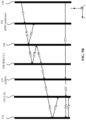
- FIG. 2 A illustrates a schematic diagram of a director configuration 200 of cholesteric liquid crystals (“CLCs”)
- FIG. 2 B illustrates polarization selective reflectivity of the CLCs shown in FIG. 2 A , according to an embodiment of the present disclosure.
- CLCs are liquid crystals that have a helical structure and, thus, exhibit a chirality, i.e., a handedness.
- CLCs are also known as chiral nematic liquid crystals. As shown in FIG. 2 A , nematic LC molecules may be represented by solid rods.
- CLCs may be arranged in layers 210 with no positional ordering within the layers 210 .
- the nematic LC directors e.g., long axes of the CLC molecules
- the nematic LC directors may rotate along an axial direction (or helical axis direction) (e.g., z-direction shown in FIG. 2 A ) of the layers 210 due to the presence of a chiral dopant.
- the LC directors may be oriented in the same direction.
- the spatial variation of the LC directors may be periodic.
- the period of the variation i.e., an axial length or distance over which the LC directors rotate by 360°, may be referred to as a helix pitch P.
- the spatial variation of the orientations of the LC directors may repeat at every half-pitch (2/P), because the LC directors oriented at 0° and ⁇ 180° are equivalent.
- the helix pitch P may determine a reflection band of the CLCs, i.e., a band of wavelengths of incident lights that may be reflected (e.g., through Bragg Reflection) by the CLCs.
- the helix pitch P may be of the same order as the wavelengths of visible lights.
- a circularly polarized incident light with the same handedness as that of the helix structure of the CLCs may be substantially (e.g., primarily) reflected, whereas a circularly polarized light with the opposite handedness may be substantially (e.g., primarily) transmitted.
- the polarization states may be unchanged.
- a right-handed CLC (“RHCLC”) 250 may exhibit a high reflection characteristic for a right-handed circular polarized (“RHCP”) light and a high transmission characteristic for a left-handed circular polarized (“LHCP”) light.
- the RHCLC 250 may substantially (e.g., primarily) reflect an RHCP light and primary transmit an LHCP light.
- a circularly polarized incident light may be transmitted by the CLCs regardless of the handedness.
- An unpolarized light or a linearly polarized light may be decomposed into an RHCP light (or an RHCP component) and an LHCP light (or an LHCP component), and the RHCLC 250 may substantially (e.g., primarily) reflect the RHCP component and substantially (e.g., primarily) transmit the LHCP component.
- FIG. 3 A illustrates a y-z cross section of a CLC reflective polarizer 300 , according to an embodiment of the present disclosure.
- the CLC reflective polarizer 300 may be an embodiment of the circular reflective polarizer 108 .
- the CLC reflective polarizer 300 may include two parallel substrates 305 (e.g., a first substrate and a second substrate) and a CLC layer 315 disposed between the two substrates 305 .
- the axial or helical axis direction of CLCs in the CLC layer 315 is along the z-direction.
- At least one (e.g., each) of the substrates 305 may be provided with an alignment layer 310 .
- the alignment layer 310 may be configured to provide an initial alignment of the CLCs in the CLC layer 315 .
- the two alignment layers 310 may provide anti-parallel homogeneous alignments to the CLCs.
- the substrates 305 may be substantially transparent in the visible band (about 380 nm to about 700 nm).
- the substrates 305 may also be transparent in some or all of the infrared (“IR”) band (about 700 nm to about 1 mm).
- IR infrared
- Each of the substrates 305 may include a suitable material that is substantially transparent to lights in the above-listed wavelength range, e.g., glass, plastic, sapphire, etc.
- the substrates 305 may be rigid or flexible.
- At least one (e.g., each) of the substrates 305 may be a part of another optical device or another optoelectrical device.
- at least one (e.g., each) of the substrates 305 may be a part of a functional device, such as a display screen.
- at least one (e.g., each) of the substrates 305 may be a part of an optical lens assembly, such as the pancake lens assembly 100 shown in FIG. 1 .
- the CLC layer 315 may have a helical structure that includes a constant helix pitch distribution.
- the axis of the helix may be normal to the surface of the CLC layer 315 .
- the helix pitch may be of the same order as the wavelengths of visible lights, and the CLC layer 315 may have a reflection band in the visible spectrum.
- the CLC reflective polarizer 300 may be a narrowband CLC reflective polarizer with a narrow reflection bandwidth (e.g., tens of nanometers).
- the CLC reflective polarizer 300 may be operated along with a narrowband light source (e.g., a 10-nm-bandwidth monochromatic light source).
- a circularly polarized incident light with the same handedness as the helix structure of the CLC reflective polarizer 300 may be substantially (e.g., primarily) reflected, whereas a circularly polarized light with the opposite handedness may be substantially (e.g., primarily) transmitted.
- the CLC reflective polarizer 300 shown in FIG. 3 A may be a right-handed CLC (“RHCLC”) refractive circular polarizer 300 .
- Unpolarized lights 302 and 304 having wavelengths within the reflection band of the CLC reflective polarizer 300 may be incident onto the CLC reflective polarizer 300 at a small incidence angle ⁇ 1 (including zero incidence angle) and a large incidence angle ⁇ 2 , respectively.
- the unpolarized light 302 may be decomposed into a right-handed circularly polarized (“RHCP”) light 302 R and a left-handed circularly polarized (“LHCP”) light 302 L.
- RHCP right-handed circularly polarized
- LHCP left-handed circularly polarized
- the propagating direction of the unpolarized light 302 may be aligned substantially parallel with the helical axis of the helical structure. Accordingly, the unpolarized light 302 may encounter a substantially circular cross section of the helixes of the CLCs in the RHCLC reflective polarizer 300 .
- the LHCP light 302 L may be substantially (e.g., primarily) transmitted (e.g., about 80% to about 100% transmitted) by the RHCLC refractive circular polarizer 300 as an LHCP light 302 L′
- the RHCP light 302 R may be substantially (e.g., primarily) reflected (e.g., about 80% to about 100% reflected) by the RHCLC refractive circular polarizer 300 as an RHCP light 302 R′.
- the unpolarized light 304 may be decomposed into an RHCP light 304 R and an LHCP light 304 L. Due to the large incidence angle ⁇ 2 , the unpolarized light 304 may encounter an elliptical cross section of the helixes of the CLCs in the RHCLC reflective polarizer 300 . Thus, the LHCP light 304 L and the RHCP light 304 R may be distorted when propagating through the RHCLC refractive circular polarizer 300 , which may reduce the transmittance of the LHCP light 304 L and the reflectance of the RHCP light 304 R. That is, the reflectance of the LHCP light 304 L may be increased, and the transmittance of the RHCP light 304 R may be increased.
- a portion of the unpolarized light 304 may be reflected by the RHCLC reflective polarizer 300 as a reflected light 304 ′, which may include a combination of an RHCP light and an LHCP light. Accordingly, the reflected light 304 ′ may be elliptically polarized.
- another portion of the unpolarized light 304 may be transmitted by the RHCLC reflective polarizer 300 as a transmitted light 304 ′′, which may include a combination of an RHCP light and an LHCP light. Accordingly, the transmitted light 304 ′′ may be elliptically polarized.
- one or more compensation films may be paired with the CLC reflective polarizer 300 to provide a polarization compensation at large incidence angles.
- the CLC reflective polarizer may include a plurality of CLC layers stacked together.
- the CLC layers may have narrow reflection bandwidths corresponding to narrowband light sources (e.g., 10-nm-bandwidth) emitting lights in different colors.
- the reflection bandwidths of the respective CLC layers may be superimposed, such that an overall reflection bandwidth of the CLC reflective polarizer may be broadened.
- An exemplary CLC reflective polarizer 320 will be explained with reference to FIG. 3 B .
- a variation of helix pitch e.g., a pitch gradient
- An exemplary CLC reflective polarizer 340 will be explained with reference to FIG. 3 C .
- FIG. 3 B illustrates a cross section of a CLC reflective polarizer 320 , according to another embodiment of the present disclosure, and the CLC reflective polarizer 320 shown in FIG. 3 B may include elements, structures, or functions that are the same as or similar to those of the CLC reflective polarizer 300 shown in FIG. 3 A . Detailed descriptions of the same or similar elements, structures, or functions can refer to the above descriptions with respect to FIG. 3 A .
- the CLC reflective polarizer 320 may include a plurality of CLC layers stacked together. Each of the CLC layers may have a helical structure with a constant helix pitch distribution. The helical pitches may spatially vary between layers.
- the CLC layers may have narrow reflection bandwidths corresponding to the bandwidths of narrowband light sources (e.g., 10-nm-bandwidth) emitting lights in different colors.
- the reflection bands of the CLC layers may not overlap with each other.
- the reflection bands of the CLC layers may slightly overlap with each other, such that an overall reflection band of the CLC reflective polarizer 320 may be continuous and broadened.
- Each CLC layer may be configured to substantially (e.g., primarily) reflect a circularly polarized incident light having a wavelength within the reflection band and having the same handedness as that of the helix structure of the CLC layer, and substantially (e.g., primarily) transmit a circularly polarized incident light having a wavelength within the reflection band and having the opposite handedness.
- Each CLC layer may transmit incident lights having wavelengths outside of the reflection band.
- each CLC layer may be disposed between two parallel substrates 305 . At least one (e.g., each) of the substrates 305 may be provide with an alignment layer 310 may be respectively disposed. In some embodiments, each CLC layer may be disposed between two substrates 305 . In some embodiments, two adjacent CLC layers may share a same substrate disposed between the two adjacent CLC layers, as shown in FIG. 3 B .
- FIG. 3 B shows that the CLC reflective polarizer 320 may include three CLC layers 325 , 330 , and 335 , each of which may have a helical structure that includes a respective constant helix pitch distribution.
- the helical pitches of the CLC layers 325 , 330 , and 335 may be different, e.g., gradually increase.
- the CLC layers 325 , 330 , and 335 may have narrow reflection bandwidths corresponding to those of a plurality of narrowband light sources (e.g., 10-nm-bandwidth) configured to emit lights in different colors.
- the CLC layers 325 , 330 , and 335 may have a reflection band in the wavelength ranges of blue, green and red lights, respectively, and the CLC layers 325 , 330 and 335 may be paired with narrowband blue, green and red light sources having a central wavelength of about 448 nm, 524 nm, and 638 nm, respectively.
- the CLC reflective polarizer 320 shown in FIG. 3 B may be a right-handed CLC (“RHCLC”) refractive circular polarizer 320 .
- Unpolarized lights 322 , 324 , and 364 may have wavelengths within the reflection bands of the CLC layers 325 , 330 , and 335 , respectively.
- the unpolarized lights 322 , 324 , and 364 may be blue, green, red lights, respectively.
- the unpolarized lights 322 , 324 , and 326 may be incident onto the CLC reflective polarizer 300 at a small incidence angle (including the zero-degree incidence angle). The incidence angles may or may not be the same.
- the unpolarized light (e.g., blue light) 322 may be decomposed into an RHCP light 322 R and an LHCP light 322 L. Because the wavelength of the unpolarized light (e.g., blue light) 322 falls within the reflection band of the CLC layer 325 , the LHCP light 322 L may be substantially (e.g., primarily) transmitted (e.g., about 80% to about 100% transmitted) by the CLC layer 325 as an LHCP light 322 L′, and the RHCP light 322 R may be substantially (e.g., primarily) reflected (e.g., about 80% to about 100% reflected) by the CLC layer 325 as an RHCP light 322 R′. Because the wavelength of the LHCP light 322 L′ is not within the reflection bands of the CLC layers 330 and 335 , the LHCP light 322 L′ may be transmitted through the CLC layers 325 and 330 .
- the unpolarized light (e.g., green light) 324 may be decomposed into an RHCP light 324 R and an LHCP light 324 L. Because the wavelength of the unpolarized light (e.g., green light) 324 is not within the reflection band of the CLC layer 325 , the unpolarized light (e.g., green light) 324 may be transmitted through the CLC layer 325 .
- the LHCP light 324 L may be substantially (e.g., primarily) transmitted (e.g., about 80% to about 100% transmitted) by the CLC layer 330 as an LHCP light 324 L′
- the RHCP light 324 R may be substantially (e.g., primarily) reflected (e.g., about 80% to about 100% reflected) by the CLC layer 330 as a RHCP light 324 R′.
- the LHCP light 324 L′ may be transmitted through the CLC layer 335 . Because the wavelength of the RHCP light 324 R′ is not within the reflection bands of the CLC layer 325 , the RHCP light 324 R′ may be transmitted through the CLC layer 325 .
- the unpolarized light (e.g., red light) 326 may be decomposed into an RHCP light 326 R and an LHCP light 326 L. Because the wavelength of the unpolarized light (e.g., red light) 326 is not within the reflection bands of the CLC layer 325 and 330 , the unpolarized light (e.g., red light) 326 may be substantially (e.g., primarily) transmitted through the CLC layers 325 and 330 .
- the LHCP light 326 L may be substantially (e.g., primarily) transmitted (e.g., about 80% to about 100% transmitted) by the CLC layer 335 as an LHCP light 326 L′
- the RHCP light 326 R may be substantially (e.g., primarily) reflected (e.g., about 80% to about 100% reflected) by the CLC layer 335 as an RHCP light 326 R′. Because the wavelength of the RHCP light 326 R′ is not within the reflection bands of the CLC layers 330 and 325 , the RHCP light 326 R′ may be transmitted through the CLC layers 330 and 325 .
- FIG. 3 C illustrates a cross section of a CLC reflective polarizer 340 , according to another embodiment of the present disclosure.
- the CLC reflective polarizer 340 may include elements, structures, or functions that are the same as or similar to those included in the reflective polarizer 300 shown in FIG. 3 A or the reflective polarizer 320 shown in FIG. 3 B . Detailed descriptions of the same or similar elements, structures, or functions can refer to the above descriptions with respect to FIG. 3 A or FIG. 3 B .
- the CLC reflective polarizer 340 may include two parallel substrates 305 and a CLC layer 345 disposed between the two substrates 305 .
- At least one (e.g., each) of the substrates 305 may be provided with an alignment layer 310 , which may provide an initial alignment for the CLCs in the CLC layer 345 .
- the CLC layer 345 may have a helical structure that includes a spatially varying helix pitch distribution, e.g., the helix pitch may gradually increase along the +z-axis direction (or the thickness direction).
- the reflection band of the CLC layer 345 may cover a broad band.
- the lights having a spectrum in the covered broad band and the same handedness as that of the helical structures of the CLC reflective polarizer 340 may be substantially (e.g., primarily) reflected by the CLC reflective polarizer 340 .
- the CLC reflective polarizer 340 may be referred to as a broadband CLC reflective polarizer 340 .
- the CLC reflective polarizer 340 may be paired with a broadband polychromatic light source, such as a 300-nm-bandwidth light source covering the visible wavelength range.
- the CLC reflective polarizer 340 may be a right-handed CLC (“RHCLC”) refractive circular polarizer 340 having a 300-nm-bandwidth reflection band covering the visible wavelength range.
- RHCLC right-handed CLC
- a broadband unpolarized light 342 may be incident onto a shorter pitch side (e.g., the side where the helical pitch is shorter) of the CLC reflective polarizer 340 at a substantially small incidence angle (including a zero-degree incidence angle).
- the broadband unpolarized light 342 may be decomposed into an unpolarized blue light 3422 , an unpolarized green light 3424 , and an unpolarized red light 3426 having a central wavelength of about 448 nm, about 524 nm, and about 638 nm, respectively.
- Each of the unpolarized blue light 3422 , the unpolarized green light 3424 , and the unpolarized red light 3426 may be decomposed into an RHCP light (or component) and an LHCP light (or component).
- the RHCP component of the unpolarized blue light 3422 , the unpolarized green light 3424 , and the unpolarized red light 3426 may be substantially (e.g., primarily) reflected (e.g., about 80% to about 100% reflected) by the CLC layer 345 as an RHCP blue light 3422 R′, an RHCP green light 3424 R′, and an RHCP red light 3426 R′, respectively.
- the LHCP component of the unpolarized blue light 3422 , the unpolarized green light 3424 , and the unpolarized red light 3426 may be substantially (e.g., primarily) transmitted (e.g., about 80% to about 100% transmitted) by the CLC layer 345 as an LHCP blue light 3422 L′, an LHCP green light 3424 L′ and an LHCP red light 3426 L′, respectively.
- the broadband CLC reflective polarizer 340 may be fabricated based on CLC and/or polymer composites.
- CLCs may be mixed with mono-functional chiral monomers, multi-functional monomers, and/or a photo-initiator.
- the mixture may be filled into a cell formed by two parallel substrates and the mixture may be disposed between the two substrates.
- the cell may be irradiated by, e.g., a UV light, and the monomers may be polymerized. During the polymerization, a UV intensity gradient may be generated across the cell in the thickness direction, which in turn produces a free radical density gradient.
- the chiral monomers When the chiral monomers diffuse to the high free radical density region, the chiral monomers may be polymerized there. Thus, the formed chiral polymer density may vary across the cell, which induces a variation of the helix pitch of the CLCs.
- the helical structure with a pitch gradient may be stabilized by the crosslinked multi-functional monomers after the polymerization.
- FIG. 4 illustrates a schematic optical path of the pancake lens assembly 100 shown in FIG. 1 , according to an embodiment of the present disclosure.
- the first optical element 105 and the second optical element 110 are omitted in FIG. 4 .
- letter “R” following a number denotes a right-handed circularly polarized (“RHCP”) light
- letter “L” following a number denotes a left-handed circularly polarized (“LHCP”) light.
- the electronic display 150 may generate an unpolarized image light 121 .
- the first circular absorptive polarizer 102 and the second circular absorptive polarizer 112 may be a right-handed circular absorptive polarizer (“RHC polarizer”) and a left-handed circular absorptive polarizer (“LHC polarizer”), respectively.
- the circular reflective polarizer 108 may be a right-handed CLC (“RHCLC”) reflective polarizer.
- the electronic display 150 , the first circular absorptive polarizer 102 , the circular reflective polarizer 108 , and the second circular absorptive polarizer 112 are drawn as having flat surfaces. In some embodiments, one or more of the electronic display 150 , the first circular absorptive polarizer 102 , the circular reflective polarizer 108 , and the second circular absorptive polarizer 112 may have curved surfaces.
- the unpolarized image light 121 may be transmitted by the first circular absorptive polarizer 102 (e.g., a right-handed circular absorptive polarizer) as an RHCP light 123 R towards the mirror 104 .
- a first portion of the RHCP light 123 R may be reflected by the mirror 104 as an LHCP light 125 L propagating towards the first circular absorptive polarizer 102 .
- a second portion of the RHCP light 123 R may be transmitted by the mirror 104 as an RHCP light 125 R propagating toward the circular reflective polarizer 108 (e.g., an RHCLC reflective polarizer).
- the LHCP light 125 L may be blocked (e.g., absorbed) by the first circular absorptive polarizer 102 (e.g., a right-handed circular absorptive polarizer) from propagating towards the electronic display 150 .
- the RHCLC reflective polarizer 108 may substantially (e.g., primarily) reflect an RHCP light and transmit an LHCP light.
- the RHCP light 125 R propagating in the +z-direction may be substantially (e.g., primarily) reflected by the RHCLC reflective polarizer 108 as an RHCP light 127 R propagating in the ⁇ z-direction, which may be further reflect by the mirror 104 as an LHCP light 129 L.
- the LHCP light 129 L may be substantially (e.g., primarily) transmitted by the RHCLC reflective polarizer 108 as an LHCP light 131 L toward the second circular absorptive polarizer 112 (e.g., a left-handed circular absorptive polarizer).
- the LHCP light 131 L may be transmitted by the second circular absorptive polarizer 112 as an LHCP light 133 L that may be delivered to the eye 170 .
- the second circular absorptive polarizer 112 may be configured to reduce the intensity of an undesirable ghost image caused by an image light 121 ′ directly received from the electronic display 150 .
- the image light 121 ′ may be an unpolarized light.
- the second circular absorptive polarizer 112 (e.g., a left-handed circular absorptive polarizer) may transmit the left-handed circularly polarized component of the image light 121 ′ as an LHCP light 122 L, and absorb the right-handed circularly polarized component of the image light 121 ′, thereby reducing the intensity of an undesirable ghost image caused by the image light 121 ′.
- the second circular absorptive polarizer 112 may also function as an anti-narcissus film.
- the LHCP light 133 L and the LHCP light 122 L may be reflected by the eye 170 as an RHCP light 135 R and an RHCP light 124 R each propagating in the ⁇ z-direction.
- both of the RHCP light 135 R and the RHCP light 124 R may be blocked (e.g., absorbed) by the second circular absorptive polarizer 112 (e.g., a left-handed circular absorptive polarizer).
- the second circular absorptive polarizer 112 e.g., a left-handed circular absorptive polarizer.
- narcissus may be suppressed, and the user may not observe the image of the eye 170 .
- FIG. 4 shows that each of the image light 121 and 121 ′ emitted from the electronic display 150 is an unpolarized light.
- the first circular absorptive polarizer 102 may be omitted.
- the light emitted from the electronic display 150 may be a linearly polarized light, and a quarter-wave plate (“QWP”) may be arranged between the electronic display 150 and the mirror 104 to convert the linearly polarized light to a circularly polarized light, e.g., an RHCP light.
- QWP quarter-wave plate
- FIG. 5 A illustrates a schematic diagram of a pancake lens assembly 500 , which may be included in the system 10 , according to another embodiment of the present disclosure.
- the pancake lens assembly 500 may include elements, structures, or functions that are the same as or similar to those of the pancake lens assembly 100 shown in FIG. 1 . Detailed descriptions of the same or similar elements, structures, or functions can refer to the above descriptions with respect to FIG. 1 . As shown in FIG. 1 .
- a QWP 125 and a linear polarizer 130 may be arranged in an optical series and disposed at the second surface of the second optical element 110 .
- the QWP 125 may be disposed between the linear polarizer 130 and the first circular reflective polarizer 108 at the second surface of the second optical element 110 .
- Each of the QWP 125 and the linear polarizer 130 may be a film or coating disposed at (e.g., bonded to or formed on) the second surface of the second optical element 110 .
- the QWP 125 and the linear polarizer 130 may be disposed at the first surface of the second optical element 110 .
- the QWP 125 may be configured to transmit an image light received from the circular reflective polarizer 108 toward the linear polarizer 130 .
- the linear polarizer 130 may be disposed between the QWP 125 and the eye 170 .
- a polarization axis of the QWP 125 may be oriented relative to the transmission axis of the linear polarizer 130 to convert a linearly polarized light to a circularly polarized light or vice versa for a visible spectrum and/or infrared spectrum.
- the QWP 125 may include a multi-layer birefringent material (e.g., polymer or liquid crystals) to produce a quarter wave birefringence across a wide spectral range.
- an angle between the polarization axis (e.g., fast axis) of the QWP 125 and the transmission axis of the linear polarizer 130 may be approximately 45 degrees.
- FIG. 5 B illustrates a schematic optical path of the pancake lens assembly 500 in FIG. 5 A , according to an embodiment of the present disclosure.
- the first optical element 105 and the second optical element 110 are omitted.
- the optical path of the image light 121 from the electronic display 150 to the QWP 125 may have components that are similar to those included in the optical path of the image light 121 from the electronic display 150 to the second circular absorptive polarizer 112 in FIG. 4 .
- the optical path components that are the same as or similar to those shown in FIG. 4 are not repeated.
- the difference between the optical paths shown in FIG. 5 B and FIG. 4 is that, in FIG.
- the LHCP light 131 L may be converted to an s-polarized light 133 s by the QWP 125 (note the letter “s” following a number denotes s-polarization).
- the linear polarizer 130 arranged between the QWP 125 and the eye 170 may be configured to transmit an s-polarized light and block a p-polarized light.
- the s-polarized light 133 s may be transmitted by the linear polarizer 130 as an s-polarized light 135 s , which may be focused to the eye 170 .
- the unpolarized image light 121 ′ incident onto the QWP 125 which is directly received from the electronic display 150 , may be transmitted as an unpolarized light 123 ′ toward the linear polarizer 130 .
- the s-polarized component of the unpolarized light 123 ′ may be transmitted by the linear polarizer 130 as an s-polarized light 125 's, and the p-polarized component of the unpolarized light 123 ′ may be blocked (e.g., absorbed) by the linear polarizer 130 , thereby reducing the intensity of an undesirable ghost image caused by the image light 121 ′ directly received from the electronic display 150 .
- the combination of the QWP 125 and the linear polarizer 130 may also function as an anti-narcissus film.
- the s-polarized light 135 s and the s-polarized light 125 's may be reflected by the eye 170 as a p-polarized light 137 p and a p-polarized light 197 p propagating in the ⁇ z-direction, respectively.
- the linear polarizer 130 transmits an s-polarized light and blocks a p-polarized light, both of the p-polarized light 137 p and the p-polarized light 197 p may be blocked (e.g., absorbed) by the linear polarizer 130 . Accordingly, the narcissus may be suppressed, and the user may not observe the image of the eye 170 .
- FIG. 6 A illustrates a schematic diagram of a pancake lens assembly 600 , which may be included in the system 10 , according to another embodiment of the present disclosure.
- the pancake lens assembly 600 may include elements, structures, or functions that are the same as or similar to those of the pancake lens assembly 500 shown in FIG. 5 A . Descriptions of the same or similar elements, structures, or functions may refer to the descriptions rendered above with respect to FIG. 5 A . As shown in FIG.
- the pancake lens assembly 600 may include the QWP 125 (e.g., a first QWP), the linear polarizer 130 , and a second QWP 135 , each of which may be a film or coating disposed at (e.g., bonded to or formed on) the second surface of the second optical element 110 .
- the first QWP 125 , the linear polarizer 130 , and the second QWP 135 may be disposed at (e.g., bonded to or formed on) the first surface of the second optical element 110 .
- the first QWP 125 may be configured to transmit an image light output from the circular reflective polarizer 108 toward the linear polarizer 130 .
- a polarization axis of the first QWP 125 may be oriented relative to the transmission axis of the linear polarizer 130 to convert a linearly polarized light into a circularly polarized light or vice versa for a visible spectrum and/or infrared spectrum.
- the second QWP 135 may be configured to transmit an image light output from the linear polarizer 130 toward the eye 170 .
- a polarization axis of the second QWP 135 may be oriented relative to the transmission axis of the linear polarizer 130 to convert a linearly polarized light into a circularly polarized light or vice versa for a visible spectrum and/or infrared spectrum.
- FIG. 6 B illustrates a schematic optical path of the pancake lens assembly 600 shown in FIG. 6 A , according to an embodiment of the present disclosure.
- the similarities between the optical paths shown in FIG. 6 B and FIG. 5 B are not repeated.
- the optical path of the image light 121 from the electronic display 150 to the linear polarizer 130 may be similar, e.g., the light output from the linear polarizer 130 may be an s-polarized light 135 s .
- the difference between the optical paths shown in FIG. 6 B and FIG. 5 B is that, in FIG.
- the second QWP 135 may convert the s-polarized light 135 s output from the linear polarizer 130 into an LHCP light 137 L, which may be focused to the eye 170 .
- the unpolarized image light 121 ′ incident onto the first QWP 125 which is directly received from the electronic display 150 , may be transmitted as an unpolarized light 123 ′ toward the linear polarizer 130 .
- the s-polarized component of the unpolarized light 123 ′ may be transmitted by the linear polarizer 130 as an s-polarized light 195 s , which is converted to an LHCP light 197 L by the second QWP 135 , and the p-polarized component of the unpolarized light 123 ′ may be blocked (e.g., absorbed) by the linear polarizer 130 , thereby reducing the intensity of an undesirable ghost image caused by the image light 121 ′ directly received from the electronic display 150 .
- the combination of the first QWP 125 , the linear polarizer 130 , and the second QWP 135 may function as an enhanced anti-narcissus film.
- the LHCP light 137 L and the LHCP light 197 L may be reflected by the eye 170 as an RHCP light 139 R and an RHCP light 199 R propagating in the ⁇ z-direction, respectively.
- the RHCP light 139 R and the RHCP light 199 R may be converted into a p-polarized light 141 p and a p-polarized light 191 p by the second QWP 135 , respectively.
- both the p-polarized light 141 p and the p-polarized light 191 p may be blocked (e.g., absorbed) by the linear polarizer 130 . Accordingly, the narcissus may be suppressed, and the user may not observe the image of the eye 170 .
- the CLC reflective polarizer 108 that is arranged between the first QWP 125 and the mirror 104 may be a first CLC reflective polarizer.
- the pancake lens assembly 600 may further include a second CLC reflective polarizer disposed between the electronic display 150 and the mirror 104 to enhance the light transmittance of the pancake lens assembly 600 , thereby increasing the light efficiency of an optical assembly or system including the pancake lens assembly 600 and the electronic display 150 .
- Exemplary structures are shown in FIG. 7 A , FIG. 7 C , and FIG. 7 D .
- FIG. 7 A illustrates a schematic diagram of a pancake lens assembly 700 , which may be included in the system 10 , according to another embodiment of the present disclosure.
- FIG. 7 A may include elements, structures, or functions that are the same as or similar to those of the pancake lens assembly 500 shown in FIG. 5 A , or the pancake lens assembly 600 shown in FIG. 6 A . Descriptions of the same or similar elements, structures, or functions may refer to the above descriptions with respect to FIG. 5 A and FIG. 6 A .
- the first CLC reflective polarizer 108 may be disposed at the second surface of the second optical element 110 .
- a second CLC reflective polarizer 106 may be disposed at the first surface of the first optical element 105 .
- the second CLC reflective polarizer 106 may be arranged between the mirror 104 and the electronic display 150 .
- the second CLC reflective polarizer 106 may be a film or coating disposed at (e.g., bonded to or formed on) the first surface of the first optical element 105 .
- the second CLC reflective polarizer 106 may be disposed at the second surface of the first optical element 105 , between the mirror 104 and the first optical element 105 .
- the helical structures of the first CLC reflective polarizer 108 and the second CLC reflective polarizer 106 may be configured with opposite handednesses.
- FIG. 7 B illustrates a schematic optical path of the pancake lens assembly 700 shown in FIG. 7 A , according to an embodiment of the present disclosure.
- the optical path shown in FIG. 7 B may include similar or the same optical path segments as the optical path shown in FIG. 5 B . Descriptions of the same or similar optical path segments may refer to the above descriptions of FIG. 5 B .
- the first CLC reflective polarizer 108 may be an RHCLC reflective polarizer and the second CLC reflective polarizer 106 may be an LHCLC reflective polarizer.
- the electronic display 150 may emit an unpolarized image light 121 toward the LHCLC reflective polarizer 106 .
- the unpolarized image light 121 may be decomposed into an RHCP light 121 R and an LHCP light 121 L.
- the LHCLC reflective polarizer 106 may substantially (e.g., primarily) transmit the RHCP light 121 R as an RHCP light 141 R toward the mirror 104 .
- a first portion of the RHCP light 141 R may be reflected by the mirror 104 as an LHCP light 143 L propagating toward the LHCLC reflective polarizer 106
- a second portion of the RHCP light 141 R may be transmitted by the mirror 104 as an RHCP light 143 R propagating toward the RHCLC reflective polarizer 108 .
- the subsequent optical path of the RHCP light 143 R in FIG. 7 B may be similar to that of the RHCP light 125 R in FIG. 5 B , the details of which are not repeated.
- the LHCP light 143 L may be substantially (e.g., primarily) reflected by the LHCLC reflective polarizer 106 as an LHCP light 144 L, a portion of which may be transmitted by the mirror 104 as an LHCP light 146 L propagating toward the RHCLC reflective polarizer 108 . Then the LHCP light 146 L may be substantially (e.g., primarily) transmitted by the RHCLC reflective polarizer 108 as an LHCP light 148 L, which may be converted into an s-polarized light 150 s by the QWP 125 .
- the s-polarized light 150 s may be transmitted through the linear polarizer 130 as an s-polarized light 152 s , which may be focused to the eye 170 .
- the image light 143 L reflected by the mirror 104 away from the eye 170 which may not be directed to the eye 170 if the second CLC reflective polarizer 106 were not included, may be reflected back to the eye 170 , thereby increasing the light transmittance and achieving a double pancake configuration.
- the double pancake configuration may be a high transmittance pancake configuration for imaging and illumination applications.
- FIG. 7 C illustrates a schematic diagram of a pancake lens assembly 730 , which may be included in the system 10 , according to another embodiment of the present disclosure.
- the pancake lens assembly 730 shown in FIG. 7 C may include elements, structures, or functions that are the same as or similar to those of the pancake lens assembly 500 shown in FIG. 5 A , the pancake lens assembly 600 shown in FIG. 6 A , or the pancake lens assembly 700 shown in FIG. 7 A . Descriptions of the same or similar elements, structures, or functions may refer to the above descriptions with respect to FIG. 5 A , FIG. 6 A , and FIG. 7 A .
- the first CLC reflective polarizer 108 may be disposed at the second surface of the second optical element 110 .
- the second CLC reflective polarizer 106 and the mirror 104 may be disposed at the first surface of the first optical element 105 .
- the second CLC reflective polarizer 106 may be arranged between the mirror 104 and the electronic display 150 .
- the first optical element 105 and the second optical element 110 may be arranged between the first CLC reflective polarizer 108 and the mirror 104 (also between the first CLC reflective polarizer 108 and the second CLC reflective polarizer 106 ).
- the optical path of the pancake lens assembly 730 shown in FIG. 7 C may include similar or the same optical path segments as the optical path shown in FIG. 7 B . Descriptions of the same or similar optical path segments may refer to the above descriptions of FIG. 7 B .
- FIG. 7 D illustrates a schematic diagram of a pancake lens assembly 750 , which may be included in the system 10 , according to another embodiment of the present disclosure.
- the pancake lens assembly 750 shown in FIG. 7 D may include elements, structures, or functions that are the same as or similar to those of the pancake lens assembly 500 shown in FIG. 5 A , the pancake lens assembly 600 shown in FIG. 6 A , the pancake lens assembly 700 shown in FIG. 7 A , or the pancake lens assembly 730 shown in FIG. 7 C . Descriptions of the same or similar elements, structures, or functions may refer to the above descriptions with respect to FIG. 5 A , FIG. 6 A , FIG. 7 A , and FIG. 7 C . As shown in FIG.
- the pancake lens assembly 750 may include a third optical element (e.g., a third lens) 120 having a first surface facing a direction toward the electronic display 150 and a second surface facing a direction toward the eye 170 .
- the first optical element 105 may be disposed between the third optical element 120 and the second optical element 110 .
- the first CLC reflective polarizer 108 may be disposed at the second surface of the second optical element 110 .
- the second CLC reflective polarizer 106 may be disposed at the first surface of the third optical element 120 .
- the third optical element 120 may be disposed between the mirror 104 and the second CLC reflective polarizer 106 .
- the first optical element 105 and the second optical element 110 may be disposed between the first CLC reflective polarizer 108 and the mirror 104 .
- the optical path of the pancake lens assembly 750 shown in FIG. 7 D may include similar or the same optical path segments as the optical path shown in FIG. 7 B . Descriptions of the same or similar optical path segments may refer to the above descriptions of FIG. 7 B .
- the electronic display 150 may be any suitable display.
- the electronic display 150 may include a self-emissive panel, such as an organic light-emitting diode (“OLED”) display panel, a micro light-emitting diode (“micro-LED”) display panel, a quantum dot (“QD”) display panel, or a combination thereof.
- OLED organic light-emitting diode
- micro-LED micro light-emitting diode
- QD quantum dot
- the electronic display 150 may include a non-emissive display, i.e., a display panel that is illuminated by an external light source, such as a liquid crystal display (“LCD”) panel, a liquid-crystal-on-silicon (“LCoS”) display panel, or a digital light processing (“DLP”) display panel, or a combination thereof.
- an external light source such as a liquid crystal display (“LCD”) panel, a liquid-crystal-on-silicon (“LCoS”) display panel, or a digital light processing (“DLP”) display panel, or a combination thereof.
- the external light source may include a laser, an LED, an OLED, or a combination thereof.
- the external light source may be narrowband or broadband.
- an unpolarized image light from the electronic display 150 has been used as an example image light emitted by the electronic display 150 .
- the electronic display 150 may be configured to emit a circularly polarized image light.
- the light transmission efficiency of the system 10 may be further increased when the electronic display 150 emits a circularly polarized image light.
- An example configuration of the electronic display 150 configured to emit a circularly polarized image light is shown in FIG. 8 .
- FIG. 8 illustrates a schematic electronic display 800 including a circular reflective polarizer, according to an embodiment of the present disclosure.
- the electronic display 800 may be an embodiment of the electronic display 150 shown in, e.g., FIG. 1 , FIG. 5 A , FIG. 6 A , FIG. 7 A , FIG. 7 C , and FIG. 7 D .
- the electronic display 800 may include a display panel 805 and a backlight module 810 .
- the display panel 805 may be a non-emissive display panel, such as an LCD panel, an LCoS display panel.
- the backlight module 810 may be configured to emit a light to illuminate the display panel 805 .
- the display panel 805 may be an emissive display panel, such as a quantum dot display panel where quantum dots absorb a backlight emitted from the backlight module 810 to emit a visible light.
- the backlight module 810 may include a backlight source assembly 8102 , a light guide plate 8104 , a circular reflective polarizer 8106 , a reflector (or reflective sheet) 8108 , and a back frame 8110 .
- the backlight module 810 may include other elements, such as a diffuser sheet and/or a prism sheet arranged between the circular reflective polarizer 8106 and the display panel 805 .
- the backlight source assembly 8102 may output backlight to a light incident surface 802 of the light guide plate 8104 .
- the backlight source assembly 8102 may be disposed adjacent the light incident surface 802 .
- the backlight source assembly 8102 may include one or more light-emitting diodes (“LEDs”), an electroluminescent panel (“ELP”), one or more cold cathode fluorescent lamps (“CCFLs”), one or more hot cathode fluorescent lamps (“HCFLs”), or one or more external electrode fluorescent lamps (“EEFLs”), etc.
- the LED backlight source may include a plurality of white LEDs or a plurality of RGB (red, green, blue) LEDs, etc.
- the light guide plate 8104 may be fabricated based on a transparent acryl resin or the like.
- the backlight entering from the light incident surface 802 may propagate inside the light guide plate 8104 , and may exit the light guide plate 8104 at a light output surface 804 to illuminate display function materials, such as liquid crystals, in the display panel 805 .
- the circular reflective polarizer 8106 may be disposed at the light output surface 804 of the light guide plate 8104 .
- the reflector 8108 may be disposed at a bottom surface 806 of the light guide plate 8104 , such that the circular reflective polarizer 8106 and reflector 8108 may be disposed at opposite sides of the light guide plate 8104 .
- the circular reflective polarizer 8106 may be configured to selectively transmit a backlight of a first polarization, and selectively reflect a backlight of a second polarization different from the first polarization (e.g., orthogonal to the first polarization) toward the light guide plate 8104 .
- the reflector 8108 may have a substantially high reflectivity (e.g., above 90%) and may convert the backlight of the second polarization into a backlight of the first polarization when reflecting the backlight received from the circular reflective polarizer 8106 back to the circular reflective polarizer 8106 .
- the reflected backlight of the first polarization may be transmitted by the circular reflective polarizer 8106 to illuminate the display panel 805 .
- a polarization recirculation may be achieved by the circular reflective polarizer 8106 and the reflector 8108 , which may significantly improve the light efficiency of the backlight module 810 .
- FIG. 8 shows that the reflector 8108 and the circular reflective polarizer 8106 are spaced apart from the light guide plate 8104 , and the circular reflective polarizer 8106 is spaced apart from the display panel 805 .
- This configuration is for discussion purposes and is not intended to limit the structural relationship between the reflector 8108 and the circular reflective polarizer 8106 and the light guide plate 8104 , and the structural relationship between the circular reflective polarizer 8106 and the display panel 805 .
- the display panel 805 , the circular reflective polarizer 8106 , the light guide plate 8104 , and/or the reflector 8108 may be stacked together without any gap.
- the circular reflective polarizer 8106 may be a CLC reflective polarizer in accordance with an embodiment of the present discourse, such as the CLC reflective polarizer 300 shown in FIG. 3 A , the CLC reflective polarizer 320 in FIG. 3 B , or the CLC reflective polarizer 340 shown in FIG. 3 C .
- a backlight emitted from the backlight source assembly 8102 may be an unpolarized backlight 811 that may be decomposed into an RHCP backlight or component 815 and an LHCP backlight or component 813 .
- the CLC reflective polarizer 8106 may substantially (e.g., primarily) reflect a circularly polarized backlight having the same handedness as the helix structure of the CLCs of the CLC reflective polarizer 8106 toward the reflector 8108 , and substantially (e.g., primarily) transmit a circularly polarized backlight having the opposite handedness toward the display panel 805 .
- the CLC reflective polarizer 8106 may be an LHCLC reflective polarizer, which may substantially (e.g., primarily) reflect the LHCP backlight 813 toward the reflector 8108 and substantially (e.g., primarily) transmit the RHCP backlight 815 toward the display panel 805 .
- the LHCP backlight 813 may be reflected by the reflector 8108 as an RHCP backlight 817 back to the CLC reflective polarizer 8106 .
- the RHCP backlight 817 may be substantially (e.g., primarily) transmitted by the CLC reflective polarizer 8106 as an RHCP backlight 819 toward the display panel 805 .
- an unpolarized backlight may be incident onto the reflector 8108 .
- the reflected backlight from the reflector 8108 may still be unpolarized and may be incident onto the CLC reflective polarizer 8106 .
- the CLC reflective polarizer 8106 e.g., an LHCLC reflective polarizer
- the CLC reflective polarizer 8106 may substantially (e.g., primarily) reflect an LHCP backlight or component of the unpolarized backlight toward the reflector 8108 , and substantially (e.g., primarily) transmit an RHCP backlight or component of the unpolarized backlight toward the display panel 805 .
- the reflector 8108 may reflect the LHCP backlight as an RHCP backlight, which may be substantially (e.g., primarily) transmitted by the CLC reflective polarizer 8106 toward the display panel 805 .
- a polarization recirculation of the backlight may be achieved in the light guide plate 805 disposed between the CLC reflective polarizer 8106 and the reflector 8108 , which may significantly improve the light efficiency of the backlight module 800 .
- the CLC reflective polarizer 8106 may be configured according to the characteristics of the backlight source assembly 8102 .
- the reflection band of the CLC reflective polarizer 8106 may be configured to correspond to the wavelength range of the backlight source assembly 8102 .
- the CLC reflective polarizer 8106 may be configured as a narrowband CLC reflective polarizer with a constant helix pitch.
- the CLC reflective polarizer 8106 may be configured as a broadband CLC reflective polarizer with a gradient helix pitch.
- the CLC reflective polarizer 8106 may be configured to include a plurality of CLC layers stacked together with the CLC layers having different helix pitches (e.g., at least two of the CLC layers may have different helix pitches).
- the helix structures of the CLC reflective polarizer 8106 and the CLC reflective polarizer 108 may have opposite handednesses.
- the circular absorptive polarizer 102 may be omitted.
- the electronic display 800 may be implemented along with any other device, assembly, or system to provide a circularly polarized light at a high light transmittance or output efficiency. In addition, the light efficiency of a device, assembly, or system including the electronic display 800 may be improved.
- FIG. 9 illustrates a schematic diagram of an electronic display 900 , according to another embodiment of the present disclosure.
- the electronic display 900 may be an embodiment of the electronic display 150 shown in FIG. 1 , FIG. 5 A , FIG. 6 A , FIG. 7 A , FIG. 7 C , and FIG. 7 D .
- the electronic display 900 shown in FIG. 9 may include elements, structures, or functions that are the same as or similar to those of the electronic display 800 shown in FIG. 8 . Descriptions of the same or similar elements, structures, or functions may refer to the descriptions rendered above in connection with FIG. 8 .
- the electronic display 900 may be implemented along with any other device, assembly, or system to provide a circularly polarized light at a high light transmittance or output efficiency.
- the electronic display 900 may include a display panel 905 disposed between a circular reflective polarizer 910 and a reflector 915 .
- the display panel 905 may be a self-emissive panel, such as an OLED display panel, a micro-LED display panel, or a combination thereof.
- the display panel 905 may have a first surface 902 facing a viewer (e.g., an eye of the viewer, or a pancake lens assembly disclosed herein) and an opposing, parallel second surface 904 .
- the first surface 902 may be a light output surface 902 where an image light is output toward the viewer (or a pancake lens assembly disclosed herein).
- the circular reflective polarizer 910 and the reflector 915 may be disposed at the first surface 902 and the second surface 904 of the display panel 905 , respectively.
- the circular reflective polarizer 910 may be a CLC reflective polarizer 910 , such as the CLC reflective polarizer 300 shown in FIG. 3 A , the CLC reflective polarizer 320 shown in FIG. 3 B , or the CLC reflective polarizer 340 shown in FIG. 3 C .
- an image light 921 emitted from the display panel 905 may be an unpolarized image light that may be decomposed into an RHCP image light or component 923 and an LHCP image light or component 925 .
- the unpolarized image light 921 may be incident onto the CLC reflective polarizer 910 , which may substantially (e.g., primarily) reflect a circularly polarized image light having the same handedness as the helix structure of the CLCs of the CLC reflective polarizer 910 toward the reflector 915 , and substantially (e.g., primarily) transmit a circularly polarized image light with an opposite handedness toward the viewer (or a pancake lens assembly disclosed herein).
- the CLC reflective polarizer 910 may substantially (e.g., primarily) reflect a circularly polarized image light having the same handedness as the helix structure of the CLCs of the CLC reflective polarizer 910 toward the reflector 915 , and substantially (e.g., primarily) transmit a circularly polarized image light with an opposite handedness toward the viewer (or a pancake lens assembly disclosed herein).
- the CLC reflective polarizer 910 may be an LHCLC reflective polarizer, which may substantially (e.g., primarily) reflect the LHCP image light 925 toward the reflector 915 and substantially (e.g., primarily) transmit the RHCP image light 923 toward the viewer (or a pancake lens assembly disclosed herein).
- the LHCP image light 925 propagating toward the reflector 915 may be reflected by reflector 915 as an RHCP image light 927 , which may be further transmitted by the CLC reflective polarizer 910 as an RHCP image light 929 toward the viewer (or a pancake lens assembly disclosed herein).
- an unpolarized image light may be incident onto the reflector 915 directly, the reflected image light may remain unpolarized and be incident onto the CLC reflective polarizer 910 after being transmitted through the display panel 905 .
- the LHCP image light or component of the unpolarized image light may be substantially (e.g., primarily) reflected by the CLC reflective polarizer 910 toward the reflector 915
- the RHCP image light or component of the unpolarized image light may be substantially (e.g., primarily) transmitted by the CLC reflective polarizer 910 toward the viewer (or a pancake lens assembly disclosed herein).
- the reflector 915 may reflect the LHCP image light as an RHCP image light, which may be further transmitted through the CLC reflective polarizer 910 toward the viewer (or a pancake lens assembly disclosed herein). Due to the handedness selectivity of the CLC reflective polarizer 910 and the handedness reversion of the reflector 915 , a polarization recirculation of the image light may be achieved, which may significantly improve the light transmission efficiency of the display panel 905 .
- the structure of the CLC reflective polarizer 910 may be determined according to the characteristics of the display panel 905 .
- the reflection band of the CLC reflective polarizer 910 may correspond to the wavelength range of the image light emitted by the display panel 905 .
- the CLC reflective polarizer 910 may be configured as a narrowband CLC reflective polarizer with a constant helix pitch.
- the CLC reflective polarizer 910 may be configured as a broadband CLC reflective polarizer with a gradient helix pitch.
- the image light emitted by the display panel 905 includes a plurality of narrowband monochromatic lights of different colors (e.g., narrowband blue light, green light and red light)
- the CLC reflective polarizer 910 may be configured to include a plurality of CLC layers stacked together with the CLC layers having different helix pitches.
- the helix structures of the CLC reflective polarizer 910 and the CLC reflective polarizer 108 may have opposite handednesses.
- the display panel 905 may include one or more substrates for supporting and protection purposes, an anode, an emissive layer, and a cathode disposed on the substrate. Under a typical bias condition, electrons and holes may be injected from the respective electrodes into the emissive layer, where the recombination of the electrons and holes may result in light emission from the emissive layer.
- both the anode and the cathode may be transparent electrodes, and the reflector 915 may be disposed adjacent one of the anode and the cathode.
- one of the anode and cathode may be a transparent electrode and the other may be a reflective electrode, such as a metal electrode with a high reflectivity.
- the reflective electrode may be arranged at the second surface 904 of the display panel 905 and function as the reflector to realize a polarization recirculation of the image light together with the CLC reflective polarizer 910 .
- the reflector 915 may be omitted.
- FIG. 10 A illustrates a diagram of a near-eye display (“NED”) 1000 , according to another embodiment of the present disclosure.
- the NED 1000 may include a front body 1005 and a band 1010 .
- the front body 1005 may include one or more electronic display elements of the electronic display and optics block (not shown in FIG. 10 A ), an inertial measurement unit (“IMU”) 1030 , one or more position sensors 1025 , and one or more locators 1020 .
- the position sensors 1025 may be located within the IMU 1030 .
- the locators 1020 may be located at fixed positions on the front body 1005 relative to one another and relative to a reference point 1015 . In the embodiment shown in FIG.
- the reference point 1015 may be located at the center of the IMU 1030 .
- One or more of the locators 1020 may be located on a front side 1020 A, a top side 1020 B, a bottom side 1020 C, a right side 1020 D, and a left side 1020 E of the front body 1005 .
- FIG. 10 B is a cross-sectional view of the front body 1005 of the NED 1000 shown in FIG. 10 A .
- the front body 1005 may include an electronic display 1035 and a pancake lens assembly 1040 configured to provide an image light of predetermined properties to an exit pupil 1045 .
- the electronic display 1035 may be any electronic display disclosed herein, such as the electronic display 150 shown in e.g., FIG. 1 , the electronic display 800 shown in FIG. 8 , or the electronic display 900 shown in FIG. 9 .
- the pancake lens assembly 1040 may be any pancake lens assembly disclosed herein, such as the pancake lens assembly 100 shown in FIG. 1 , the pancake lens assembly 500 shown in FIG. 5 A , the pancake lens assembly 600 shown in FIG.
- the exit pupil 1045 may be at a location of the front body 1005 where an eye 1050 of a user may be positioned.
- FIG. 10 B shows a cross-section of the front body 1005 associated with a single eye 1050 .
- another electronic display separate from the electronic display 1035 may be provided for another eye of the user.
- a software module is implemented with a computer program product including a computer-readable medium containing computer program code, which can be executed by a computer processor for performing any or all of the steps, operations, or processes described.
- a hardware module may include hardware components such as a device, a system, an optical element, a controller, an electrical circuit, a logic gate, etc.
- Embodiments of the disclosure may also relate to an apparatus for performing the operations herein.
- This apparatus may be specially constructed for the specific purposes, and/or it may include a general-purpose computing device selectively activated or reconfigured by a computer program stored in the computer.
- a computer program may be stored in a non-transitory, tangible computer readable storage medium, or any type of media suitable for storing electronic instructions, which may be coupled to a computer system bus.
- the non-transitory computer-readable storage medium can be any medium that can store program codes, for example, a magnetic disk, an optical disk, a read-only memory (“ROM”), or a random access memory (“RAM”), an Electrically Programmable read only memory (“EPROM”), an Electrically Erasable Programmable read only memory (“EEPROM”), a register, a hard disk, a solid-state disk drive, a smart media card (“SMC”), a secure digital card (“SD”), a flash card, etc.
- any computing systems described in the specification may include a single processor or may be architectures employing multiple processors for increased computing capability.
- the processor may be a central processing unit (“CPU”), a graphics processing unit (“GPU”), or any processing device configured to process data and/or performing computation based on data.
- the processor may include both software and hardware components.
- the processor may include a hardware component, such as an application-specific integrated circuit (“ASIC”), a programmable logic device (“PLD”), or a combination thereof.
- ASIC application-specific integrated circuit
- PLD programmable logic device
- the PLD may be a complex programmable logic device (“CPLD”), a field-programmable gate array (“FPGA”), etc.
- elements shown in one embodiment may be included in the other embodiment.
- Elements shown in one embodiment may be repeated to form a stacked configuration.
- Elements shown in different embodiments may be combined to form a variation of the disclosed embodiments.
- Elements shown in different embodiments may be repeated and combined to form variations of the disclosed embodiments.
- Elements mentioned in the descriptions but not shown in the figures may still be included in a disclosed embodiment or a variation of the disclosed embodiment.
Landscapes
- Physics & Mathematics (AREA)
- General Physics & Mathematics (AREA)
- Optics & Photonics (AREA)
- Chemical & Material Sciences (AREA)
- Crystallography & Structural Chemistry (AREA)
- Polarising Elements (AREA)
Abstract
Description
Claims (20)
Priority Applications (6)
| Application Number | Priority Date | Filing Date | Title |
|---|---|---|---|
| US17/093,609 US11573357B2 (en) | 2019-12-04 | 2020-11-09 | Lens assembly having circular reflective polarizer |
| KR1020227020869A KR20220108785A (en) | 2019-12-04 | 2020-11-29 | Lens assembly with circular reflective polarizer |
| EP20828903.3A EP4070141A1 (en) | 2019-12-04 | 2020-11-29 | Lens assembly having circular reflective polarizer |
| CN202080084133.5A CN114761843A (en) | 2019-12-04 | 2020-11-29 | Lens assembly with circular reflective polarizer |
| PCT/US2020/062528 WO2021113156A1 (en) | 2019-12-04 | 2020-11-29 | Lens assembly having circular reflective polarizer |
| JP2022521065A JP2023504982A (en) | 2019-12-04 | 2020-11-29 | Lens assembly with circular reflective polarizer |
Applications Claiming Priority (2)
| Application Number | Priority Date | Filing Date | Title |
|---|---|---|---|
| US201962943379P | 2019-12-04 | 2019-12-04 | |
| US17/093,609 US11573357B2 (en) | 2019-12-04 | 2020-11-09 | Lens assembly having circular reflective polarizer |
Publications (2)
| Publication Number | Publication Date |
|---|---|
| US20210173134A1 US20210173134A1 (en) | 2021-06-10 |
| US11573357B2 true US11573357B2 (en) | 2023-02-07 |
Family
ID=76210878
Family Applications (1)
| Application Number | Title | Priority Date | Filing Date |
|---|---|---|---|
| US17/093,609 Active 2040-12-04 US11573357B2 (en) | 2019-12-04 | 2020-11-09 | Lens assembly having circular reflective polarizer |
Country Status (6)
| Country | Link |
|---|---|
| US (1) | US11573357B2 (en) |
| EP (1) | EP4070141A1 (en) |
| JP (1) | JP2023504982A (en) |
| KR (1) | KR20220108785A (en) |
| CN (1) | CN114761843A (en) |
| WO (1) | WO2021113156A1 (en) |
Families Citing this family (8)
| Publication number | Priority date | Publication date | Assignee | Title |
|---|---|---|---|---|
| JPWO2022260134A1 (en) * | 2021-06-10 | 2022-12-15 | ||
| EP4338005A2 (en) * | 2021-07-02 | 2024-03-20 | Apple Inc. | Electronic device with a lens module |
| TWI805207B (en) * | 2022-01-27 | 2023-06-11 | 國立陽明交通大學 | Pancake lens assembly |
| TW202407422A (en) * | 2022-03-24 | 2024-02-16 | 美商元平台技術有限公司 | Accommodation integrated folding lens assembly |
| TWI797010B (en) * | 2022-04-28 | 2023-03-21 | 大陸商業成科技(成都)有限公司 | Curved optic structure and method of manufacturing thereof |
| CN115509022B (en) * | 2022-08-17 | 2024-10-18 | 业成光电(深圳)有限公司 | Folded lens system and method of manufacturing the same |
| TWI823809B (en) * | 2023-04-13 | 2023-11-21 | 新鉅科技股份有限公司 | Optical lens assembly and head-mounted electronic device |
| WO2026044104A1 (en) * | 2024-08-21 | 2026-02-26 | Meta Platforms Technologies, Llc | Apparatus, systems, and methods for see-through augmented reality displays |
Citations (6)
| Publication number | Priority date | Publication date | Assignee | Title |
|---|---|---|---|---|
| EP0718645A2 (en) | 1994-12-19 | 1996-06-26 | Sharp Kabushiki Kaisha | Optical device and head-mounted display using said optical device |
| US5715023A (en) | 1996-04-30 | 1998-02-03 | Kaiser Electro-Optics, Inc. | Plane parallel optical collimating device employing a cholesteric liquid crystal |
| US20100177113A1 (en) | 2007-06-01 | 2010-07-15 | Gregory Gay | Optical system and display |
| US20170242258A1 (en) | 2016-02-01 | 2017-08-24 | Kopin Corporation | Embedded Reflective Eyepiece |
| US20190293978A1 (en) * | 2018-03-22 | 2019-09-26 | Liqxtal Technology Inc. | Ocular optical system |
| US20190353906A1 (en) | 2018-05-18 | 2019-11-21 | Facebook Technologies, Llc | Optical Assembly with Polarization Volume Holographic Element |
Family Cites Families (12)
| Publication number | Priority date | Publication date | Assignee | Title |
|---|---|---|---|---|
| AU7352994A (en) * | 1994-02-07 | 1995-08-21 | Richard Dennis Rallison | Intensified visual display |
| JPH11326896A (en) * | 1998-03-10 | 1999-11-26 | Dainippon Printing Co Ltd | Liquid crystal display |
| JP4419281B2 (en) * | 2000-06-13 | 2010-02-24 | コニカミノルタホールディングス株式会社 | Eyepiece optics |
| JP2002341343A (en) * | 2001-05-14 | 2002-11-27 | Nitto Denko Corp | Lighting device and liquid crystal display device |
| US7733443B2 (en) * | 2004-03-09 | 2010-06-08 | Nitto Denko Corporation | LCD comprising backlight and reflective polarizer on front panel |
| CN100501459C (en) * | 2005-05-31 | 2009-06-17 | 索尼株式会社 | Liquid crystal display, method of manufacturing optical sheet, and optical sheet |
| KR101331814B1 (en) * | 2009-12-09 | 2013-11-22 | 엘지디스플레이 주식회사 | Polariation sheet and lliquid crystal display device having therof |
| KR101836183B1 (en) * | 2010-11-04 | 2018-03-08 | 엘지디스플레이 주식회사 | Glasses for watching 3d image and method for watching of 3d image using the same |
| US10571692B2 (en) * | 2016-03-02 | 2020-02-25 | Facebook Technologies, Llc | Field curvature corrected display |
| JP6688807B2 (en) * | 2016-06-09 | 2020-04-28 | スリーエム イノベイティブ プロパティズ カンパニー | Optical system |
| US10175489B1 (en) * | 2017-07-05 | 2019-01-08 | Microsoft Technology Licensing, Llc | Compact optical system with MEMS scanners for image generation and object tracking |
| KR102490630B1 (en) * | 2017-12-26 | 2023-01-20 | 엘지디스플레이 주식회사 | Display apparatus having an eyepiece |
-
2020
- 2020-11-09 US US17/093,609 patent/US11573357B2/en active Active
- 2020-11-29 EP EP20828903.3A patent/EP4070141A1/en not_active Withdrawn
- 2020-11-29 KR KR1020227020869A patent/KR20220108785A/en not_active Ceased
- 2020-11-29 CN CN202080084133.5A patent/CN114761843A/en active Pending
- 2020-11-29 JP JP2022521065A patent/JP2023504982A/en active Pending
- 2020-11-29 WO PCT/US2020/062528 patent/WO2021113156A1/en not_active Ceased
Patent Citations (6)
| Publication number | Priority date | Publication date | Assignee | Title |
|---|---|---|---|---|
| EP0718645A2 (en) | 1994-12-19 | 1996-06-26 | Sharp Kabushiki Kaisha | Optical device and head-mounted display using said optical device |
| US5715023A (en) | 1996-04-30 | 1998-02-03 | Kaiser Electro-Optics, Inc. | Plane parallel optical collimating device employing a cholesteric liquid crystal |
| US20100177113A1 (en) | 2007-06-01 | 2010-07-15 | Gregory Gay | Optical system and display |
| US20170242258A1 (en) | 2016-02-01 | 2017-08-24 | Kopin Corporation | Embedded Reflective Eyepiece |
| US20190293978A1 (en) * | 2018-03-22 | 2019-09-26 | Liqxtal Technology Inc. | Ocular optical system |
| US20190353906A1 (en) | 2018-05-18 | 2019-11-21 | Facebook Technologies, Llc | Optical Assembly with Polarization Volume Holographic Element |
Non-Patent Citations (2)
| Title |
|---|
| International Preliminary Report on Patentability for International Application No. PCT/US2020/062528, dated Jun. 16, 2022, 9 pages. |
| International Search Report and Written Opinion dated Mar. 17, 2021, in International Application No. PCT/US2020/062528, filed on Nov. 29, 2020 (10 pages). |
Also Published As
| Publication number | Publication date |
|---|---|
| JP2023504982A (en) | 2023-02-08 |
| CN114761843A (en) | 2022-07-15 |
| KR20220108785A (en) | 2022-08-03 |
| EP4070141A1 (en) | 2022-10-12 |
| US20210173134A1 (en) | 2021-06-10 |
| WO2021113156A1 (en) | 2021-06-10 |
Similar Documents
| Publication | Publication Date | Title |
|---|---|---|
| US11573357B2 (en) | Lens assembly having circular reflective polarizer | |
| CN114341681A (en) | Optical stack for privacy display | |
| JP4931929B2 (en) | Polarization control system and display device | |
| JP2010262813A (en) | Illumination device and liquid crystal display device | |
| US20220155513A1 (en) | Liquid crystal reflective polarizer and pancake lens assembly having the same | |
| US20180017729A1 (en) | Display device | |
| CN111999898A (en) | Optical display system and display device | |
| US11624864B2 (en) | Optical device including optically anisotropic molecules having intermediate pretilt angles | |
| US12274125B2 (en) | Color conversion display with polarized emission enhancement | |
| US20220269092A1 (en) | Display device including polarization selective microlens array | |
| US11215743B2 (en) | Achromatic optical device based on birefringent materials having positive and negative birefringence dispersions | |
| US20220269120A1 (en) | Devices including birefringent medium having chirality | |
| CN104903778A (en) | Optical system providing polarized light | |
| US12066648B2 (en) | Apochromatic liquid crystal polarization hologram device | |
| US12259616B1 (en) | Heliconical liquid crystal polarization hologram and device including the same | |
| US11796881B2 (en) | Blue phase liquid crystal polarization hologram comprising liquid crystal molecules having a spatially varying in-plane orientation pattern and device including the same | |
| US20260086385A1 (en) | Optical device and luminance and color compensation method | |
| US20230152750A1 (en) | Method for birefringence patterning | |
| WO2022178345A1 (en) | Devices including birefringent medium having chirality | |
| CN117413220A (en) | Blue phase liquid crystal polarization hologram and equipment including the same | |
| WO2025239164A1 (en) | Head-mounted display | |
| WO2022245680A1 (en) | Color conversion display with polarized emission enhancement |
Legal Events
| Date | Code | Title | Description |
|---|---|---|---|
| FEPP | Fee payment procedure |
Free format text: ENTITY STATUS SET TO UNDISCOUNTED (ORIGINAL EVENT CODE: BIG.); ENTITY STATUS OF PATENT OWNER: LARGE ENTITY |
|
| STPP | Information on status: patent application and granting procedure in general |
Free format text: APPLICATION DISPATCHED FROM PREEXAM, NOT YET DOCKETED |
|
| STPP | Information on status: patent application and granting procedure in general |
Free format text: DOCKETED NEW CASE - READY FOR EXAMINATION |
|
| STPP | Information on status: patent application and granting procedure in general |
Free format text: NON FINAL ACTION MAILED |
|
| STPP | Information on status: patent application and granting procedure in general |
Free format text: RESPONSE TO NON-FINAL OFFICE ACTION ENTERED AND FORWARDED TO EXAMINER |
|
| STPP | Information on status: patent application and granting procedure in general |
Free format text: NON FINAL ACTION MAILED |
|
| AS | Assignment |
Owner name: FACEBOOK TECHNOLOGIES, LLC, CALIFORNIA Free format text: ASSIGNMENT OF ASSIGNORS INTEREST;ASSIGNORS:PENG, FENGLIN;WANG, JUNREN;HUANG, YUGE;AND OTHERS;SIGNING DATES FROM 20201109 TO 20220510;REEL/FRAME:059950/0709 |
|
| AS | Assignment |
Owner name: META PLATFORMS TECHNOLOGIES, LLC, CALIFORNIA Free format text: CHANGE OF NAME;ASSIGNOR:FACEBOOK TECHNOLOGIES, LLC;REEL/FRAME:060345/0029 Effective date: 20220318 |
|
| STPP | Information on status: patent application and granting procedure in general |
Free format text: RESPONSE TO NON-FINAL OFFICE ACTION ENTERED AND FORWARDED TO EXAMINER |
|
| STPP | Information on status: patent application and granting procedure in general |
Free format text: NOTICE OF ALLOWANCE MAILED -- APPLICATION RECEIVED IN OFFICE OF PUBLICATIONS |
|
| STPP | Information on status: patent application and granting procedure in general |
Free format text: NOTICE OF ALLOWANCE MAILED -- APPLICATION RECEIVED IN OFFICE OF PUBLICATIONS |
|
| STPP | Information on status: patent application and granting procedure in general |
Free format text: PUBLICATIONS -- ISSUE FEE PAYMENT RECEIVED |
|
| STPP | Information on status: patent application and granting procedure in general |
Free format text: PUBLICATIONS -- ISSUE FEE PAYMENT VERIFIED |
|
| STCF | Information on status: patent grant |
Free format text: PATENTED CASE |