US11566657B2 - Vibration resistant torsionally compliant transmission shaft - Google Patents
Vibration resistant torsionally compliant transmission shaft Download PDFInfo
- Publication number
- US11566657B2 US11566657B2 US16/697,485 US201916697485A US11566657B2 US 11566657 B2 US11566657 B2 US 11566657B2 US 201916697485 A US201916697485 A US 201916697485A US 11566657 B2 US11566657 B2 US 11566657B2
- Authority
- US
- United States
- Prior art keywords
- rod
- transmission shaft
- torque
- ribs
- section
- Prior art date
- Legal status (The legal status is an assumption and is not a legal conclusion. Google has not performed a legal analysis and makes no representation as to the accuracy of the status listed.)
- Active, expires
Links
- 230000005540 biological transmission Effects 0.000 title claims abstract description 164
- 238000012546 transfer Methods 0.000 claims abstract description 8
- 230000008878 coupling Effects 0.000 claims description 30
- 238000010168 coupling process Methods 0.000 claims description 30
- 238000005859 coupling reaction Methods 0.000 claims description 30
- 238000000034 method Methods 0.000 claims description 15
- 238000004519 manufacturing process Methods 0.000 claims description 6
- 239000002131 composite material Substances 0.000 claims description 5
- 239000000853 adhesive Substances 0.000 claims description 2
- 230000001070 adhesive effect Effects 0.000 claims description 2
- 239000007787 solid Substances 0.000 description 21
- 230000010355 oscillation Effects 0.000 description 15
- 239000000463 material Substances 0.000 description 8
- 238000001125 extrusion Methods 0.000 description 7
- 230000008901 benefit Effects 0.000 description 6
- 238000013461 design Methods 0.000 description 6
- 230000009365 direct transmission Effects 0.000 description 4
- 230000000694 effects Effects 0.000 description 4
- 230000007935 neutral effect Effects 0.000 description 4
- 239000011800 void material Substances 0.000 description 4
- 238000010276 construction Methods 0.000 description 2
- 230000002093 peripheral effect Effects 0.000 description 2
- 238000012360 testing method Methods 0.000 description 2
- 229910000838 Al alloy Inorganic materials 0.000 description 1
- 229910000831 Steel Inorganic materials 0.000 description 1
- 230000003466 anti-cipated effect Effects 0.000 description 1
- 230000009286 beneficial effect Effects 0.000 description 1
- 238000005219 brazing Methods 0.000 description 1
- 238000006073 displacement reaction Methods 0.000 description 1
- 238000009826 distribution Methods 0.000 description 1
- 230000004927 fusion Effects 0.000 description 1
- 238000005304 joining Methods 0.000 description 1
- 238000003754 machining Methods 0.000 description 1
- 239000011159 matrix material Substances 0.000 description 1
- 229910001092 metal group alloy Inorganic materials 0.000 description 1
- 230000008569 process Effects 0.000 description 1
- 238000012545 processing Methods 0.000 description 1
- 230000009467 reduction Effects 0.000 description 1
- 230000004044 response Effects 0.000 description 1
- 238000004513 sizing Methods 0.000 description 1
- 238000005476 soldering Methods 0.000 description 1
- 239000010959 steel Substances 0.000 description 1
- 229910000601 superalloy Inorganic materials 0.000 description 1
- 238000012956 testing procedure Methods 0.000 description 1
- 238000011144 upstream manufacturing Methods 0.000 description 1
- 238000003466 welding Methods 0.000 description 1
Images


Classifications
-
- F—MECHANICAL ENGINEERING; LIGHTING; HEATING; WEAPONS; BLASTING
- F16—ENGINEERING ELEMENTS AND UNITS; GENERAL MEASURES FOR PRODUCING AND MAINTAINING EFFECTIVE FUNCTIONING OF MACHINES OR INSTALLATIONS; THERMAL INSULATION IN GENERAL
- F16C—SHAFTS; FLEXIBLE SHAFTS; ELEMENTS OR CRANKSHAFT MECHANISMS; ROTARY BODIES OTHER THAN GEARING ELEMENTS; BEARINGS
- F16C3/00—Shafts; Axles; Cranks; Eccentrics
- F16C3/02—Shafts; Axles
-
- B—PERFORMING OPERATIONS; TRANSPORTING
- B64—AIRCRAFT; AVIATION; COSMONAUTICS
- B64C—AEROPLANES; HELICOPTERS
- B64C13/00—Control systems or transmitting systems for actuating flying-control surfaces, lift-increasing flaps, air brakes, or spoilers
- B64C13/24—Transmitting means
- B64C13/26—Transmitting means without power amplification or where power amplification is irrelevant
- B64C13/28—Transmitting means without power amplification or where power amplification is irrelevant mechanical
-
- F—MECHANICAL ENGINEERING; LIGHTING; HEATING; WEAPONS; BLASTING
- F16—ENGINEERING ELEMENTS AND UNITS; GENERAL MEASURES FOR PRODUCING AND MAINTAINING EFFECTIVE FUNCTIONING OF MACHINES OR INSTALLATIONS; THERMAL INSULATION IN GENERAL
- F16C—SHAFTS; FLEXIBLE SHAFTS; ELEMENTS OR CRANKSHAFT MECHANISMS; ROTARY BODIES OTHER THAN GEARING ELEMENTS; BEARINGS
- F16C1/00—Flexible shafts; Mechanical means for transmitting movement in a flexible sheathing
- F16C1/02—Flexible shafts; Mechanical means for transmitting movement in a flexible sheathing for conveying rotary movements
- F16C1/08—End connections
-
- F—MECHANICAL ENGINEERING; LIGHTING; HEATING; WEAPONS; BLASTING
- F16—ENGINEERING ELEMENTS AND UNITS; GENERAL MEASURES FOR PRODUCING AND MAINTAINING EFFECTIVE FUNCTIONING OF MACHINES OR INSTALLATIONS; THERMAL INSULATION IN GENERAL
- F16C—SHAFTS; FLEXIBLE SHAFTS; ELEMENTS OR CRANKSHAFT MECHANISMS; ROTARY BODIES OTHER THAN GEARING ELEMENTS; BEARINGS
- F16C2202/00—Solid materials defined by their properties
- F16C2202/02—Mechanical properties
-
- F—MECHANICAL ENGINEERING; LIGHTING; HEATING; WEAPONS; BLASTING
- F16—ENGINEERING ELEMENTS AND UNITS; GENERAL MEASURES FOR PRODUCING AND MAINTAINING EFFECTIVE FUNCTIONING OF MACHINES OR INSTALLATIONS; THERMAL INSULATION IN GENERAL
- F16C—SHAFTS; FLEXIBLE SHAFTS; ELEMENTS OR CRANKSHAFT MECHANISMS; ROTARY BODIES OTHER THAN GEARING ELEMENTS; BEARINGS
- F16C2208/00—Plastics; Synthetic resins, e.g. rubbers
- F16C2208/02—Plastics; Synthetic resins, e.g. rubbers comprising fillers, fibres
-
- F—MECHANICAL ENGINEERING; LIGHTING; HEATING; WEAPONS; BLASTING
- F16—ENGINEERING ELEMENTS AND UNITS; GENERAL MEASURES FOR PRODUCING AND MAINTAINING EFFECTIVE FUNCTIONING OF MACHINES OR INSTALLATIONS; THERMAL INSULATION IN GENERAL
- F16C—SHAFTS; FLEXIBLE SHAFTS; ELEMENTS OR CRANKSHAFT MECHANISMS; ROTARY BODIES OTHER THAN GEARING ELEMENTS; BEARINGS
- F16C2220/00—Shaping
- F16C2220/40—Shaping by deformation without removing material
- F16C2220/48—Shaping by deformation without removing material by extrusion, e.g. of metallic profiles
-
- F—MECHANICAL ENGINEERING; LIGHTING; HEATING; WEAPONS; BLASTING
- F16—ENGINEERING ELEMENTS AND UNITS; GENERAL MEASURES FOR PRODUCING AND MAINTAINING EFFECTIVE FUNCTIONING OF MACHINES OR INSTALLATIONS; THERMAL INSULATION IN GENERAL
- F16C—SHAFTS; FLEXIBLE SHAFTS; ELEMENTS OR CRANKSHAFT MECHANISMS; ROTARY BODIES OTHER THAN GEARING ELEMENTS; BEARINGS
- F16C2226/00—Joining parts; Fastening; Assembling or mounting parts
-
- F—MECHANICAL ENGINEERING; LIGHTING; HEATING; WEAPONS; BLASTING
- F16—ENGINEERING ELEMENTS AND UNITS; GENERAL MEASURES FOR PRODUCING AND MAINTAINING EFFECTIVE FUNCTIONING OF MACHINES OR INSTALLATIONS; THERMAL INSULATION IN GENERAL
- F16C—SHAFTS; FLEXIBLE SHAFTS; ELEMENTS OR CRANKSHAFT MECHANISMS; ROTARY BODIES OTHER THAN GEARING ELEMENTS; BEARINGS
- F16C2326/00—Articles relating to transporting
- F16C2326/01—Parts of vehicles in general
- F16C2326/06—Drive shafts
-
- F—MECHANICAL ENGINEERING; LIGHTING; HEATING; WEAPONS; BLASTING
- F16—ENGINEERING ELEMENTS AND UNITS; GENERAL MEASURES FOR PRODUCING AND MAINTAINING EFFECTIVE FUNCTIONING OF MACHINES OR INSTALLATIONS; THERMAL INSULATION IN GENERAL
- F16C—SHAFTS; FLEXIBLE SHAFTS; ELEMENTS OR CRANKSHAFT MECHANISMS; ROTARY BODIES OTHER THAN GEARING ELEMENTS; BEARINGS
- F16C2326/00—Articles relating to transporting
- F16C2326/43—Aeroplanes; Helicopters
-
- F—MECHANICAL ENGINEERING; LIGHTING; HEATING; WEAPONS; BLASTING
- F16—ENGINEERING ELEMENTS AND UNITS; GENERAL MEASURES FOR PRODUCING AND MAINTAINING EFFECTIVE FUNCTIONING OF MACHINES OR INSTALLATIONS; THERMAL INSULATION IN GENERAL
- F16D—COUPLINGS FOR TRANSMITTING ROTATION; CLUTCHES; BRAKES
- F16D3/00—Yielding couplings, i.e. with means permitting movement between the connected parts during the drive
-
- Y—GENERAL TAGGING OF NEW TECHNOLOGICAL DEVELOPMENTS; GENERAL TAGGING OF CROSS-SECTIONAL TECHNOLOGIES SPANNING OVER SEVERAL SECTIONS OF THE IPC; TECHNICAL SUBJECTS COVERED BY FORMER USPC CROSS-REFERENCE ART COLLECTIONS [XRACs] AND DIGESTS
- Y02—TECHNOLOGIES OR APPLICATIONS FOR MITIGATION OR ADAPTATION AGAINST CLIMATE CHANGE
- Y02T—CLIMATE CHANGE MITIGATION TECHNOLOGIES RELATED TO TRANSPORTATION
- Y02T50/00—Aeronautics or air transport
- Y02T50/40—Weight reduction
Definitions
- the present disclosure relates to a transmission shaft, for example, for a power transmission shaft assembly, and to a method of manufacturing such a transmission shaft.
- transmission shaft refers to any form of shaft which is used to transfer torque between two components, for example, a driveshaft, actuator shaft, or other output shaft delivering rotational movement.
- Torsional compliant shafts can act as springs, protecting the rest of the transmission system from sudden spikes of torque originating from jams or sudden changes of load.
- the torsional compliance is usually obtained by replacing a torsionally stiff section of a transmission shaft, typically in the form of a tube, with a solid rod of narrower section.
- the solid rod is less rigid in torsion than the tube section of the transmission shaft and provides the power transmission system with a degree of torsional compliance.
- a solid rod design also does not have as much stiffness in a transverse direction as a tubular shaft.
- it can be susceptible to harmonic vibration induced by nearby components such as engines, compressors or pumps. If the frequency of these nearby components is close to the natural frequency of the shaft it can induce resonance in the shaft. This resonance is more significant during a failure such as a loss of a rotor blade in an engine, which leads to a rotor imbalance. In these circumstances the vibrations in the rod can become severe and cause large deflections in the shaft and may lead to failure of the shaft or cause it to impact other components.
- any oscillations in the rod would be generally within predetermined limits, though it is also possible for resonance to set in at certain harmonic frequencies. Large oscillation amplitudes, for example, during “one-off” events, can induce large stresses in the transmission shaft which can lead to component failure.
- the transmission shaft will also experience large deflections in normal use.
- the transmission shaft is typically employed in areas where it is desired to reduce space and arrange components together compactly.
- the transmission shaft will therefore be positioned very close to other components. Large deflections in the shaft can therefore cause the shaft to impact the other nearby components resulting in further damage to the overall system.
- transverse (lateral) deflection can be allowed in a transmission shaft during normal use as well as during such “one-off” events when spikes of torque may be experienced. These amounts may depend on where the transmission shaft is positioned on the aircraft, for example, whether it is within the wing, in which case stricter requirements may apply. Any transmission shaft within the wing of the aircraft will also be closer to the engine which is a source of significant vibrations which may induce failure.
- the present disclosure provides a transmission shaft comprising, a first side for inputting torque, a second side for outputting torque, and a rod extending in a longitudinal direction between the first side and the second side to transfer torque along the transmission shaft.
- the rod comprises a first end provided at the first side, a second end provided at the second side and a torsional compliant section extending therebetween providing the transmission shaft with a torsional stiffness.
- the torsional compliant section comprises a cross-section which extends in the longitudinal direction to define a central core for transmitting torque directly from the first end to the second end and a radially outer section comprising a plurality ribs which extend radially and longitudinally from an outer periphery of the central core for increasing transverse stiffness of the rod.
- the first end of the rod and the first side of the transmission shaft may be coupled through a first circumferentially extending interface to deliver torque into the torsional compliant section, i.e., from the first side to the first end.
- the second end of the rod and the second side of the transmission shaft may be coupled through a second circumferentially extending interface to deliver torque out of the torsional compliant section, i.e., from the second side to the second end.
- End surfaces of the ribs of the torsional compliant section may be spaced from the first and second circumferentially extending interfaces. In other words the ribs may terminate before the first and second circumferentially extending interfaces. In this way the ribs may be de-coupled, as far as possible, from direct transmission of torque from the input side to the output side through the ribs.
- the input side may be arranged to transmit torque into the first end of the rod through the central core only.
- the ribs may be configured to be functionally isolated at the first end from the inputted torque as the torque enters the rod.
- the output side may be arranged to transmit torque out of the second end of the rod through the central core only.
- the ribs may be configured to be functionally isolated at the second end from the outputted torque as the torque exits the rod.
- the first side may be arranged to transmit torque into the first end of the rod through a first portion of a circumferential outer surface of the central core only, the ribs comprising first end surfaces which extend from the circumferential outer surface spaced from the first side and the first circumferentially extending interface so as to be functionally isolated from the inputted torque as the torque enters the first end of the rod.
- the second side may be arranged to transmit torque out of the second end of the rod through a second portion of the circumferential outer surface of the central core only, the ribs comprising second end surfaces which extend from the circumferential outer surface spaced from the second side and the second circumferentially extending interface so as to be functionally isolated from the outputted torque as the torque exits the second end of the rod.
- the transmission shaft may provide a primary load path for torque to pass along between the first side and the second side of the transmission shaft via the central core of the rod.
- the rod may be coupled to the first side and the second side so that the primary load path can only enter the first end of the rod through the central core and/or only exit from the second end of the rod through the central core.
- the first end may be viewed as the input end and the second end may be viewed as the second end.
- the transmission shaft comprises a longitudinal axis which will be linear when no torsional or lateral forces are present.
- the rod may comprise a continuous cross-section.
- the rod may have four or more ribs arranged around the central core.
- the rod may have six or eight ribs.
- the central core may have an outer diameter dimension which is more than twice the lateral thickness of any rib.
- the central core may have an outer diameter dimension which is three times or more the lateral thickness of any rib.
- the ribs may be arranged around a hollow central core.
- Fillet portions may be provided at the radially inner end of the ribs where they join the outer periphery of the central core.
- the ribs or a plurality of the ribs may comprise a laterally extending flange arranged at a radially outer end of the rib, the flange may extend in a generally circumferential or tangential direction to the rib.
- Each flange may be arranged symmetrically at the radially outer end of the rib with the rib extending along a midline of the flange.
- the laterally extending flange of one rib may be spaced from the laterally extending flange of an adjacent rib such that an axially-extending gap is present between the flanges under all working torsional loads.
- the transmission shaft may comprise a first flexible coupling provided at the first/input side with a universal joint or self-aligning bearing for inputting torque and a second flexible coupling provided at the second/output side with a universal joint or self-aligning bearing for outputting torque.
- the rod may comprise a composite material.
- the rod may comprise fibres extending longitudinally the entire length of the rod.
- the transmission shaft may be for an aircraft.
- the transmission shaft may be for driving an actuator in a wing of the aircraft.
- the transmission shaft may be able to comply with the High Level Short Duration (HLSD) curve P (+/ ⁇ 10G n ⁇ pk) of the DO160G requirements.
- HLSD High Level Short Duration
- the present disclosure provides a method of making a transmission shaft, the transmission shaft comprising a first side for inputting torque, a second side for outputting torque, a rod extending in a longitudinal direction between the first side and the second side to transfer torque along the transmission shaft, the rod comprising a first end provided at the first side, a second end provided at the second side and a torsional compliant section extending therebetween providing the transmission shaft with a torsional stiffness.
- the rod comprises a cross-section which extends in the longitudinal direction to define a central core for transmitting torque directly from the first end to the second end and a radially outer section comprising a plurality ribs which extend longitudinally and radially from an outer periphery of the central core for increasing transverse stiffness of the rod.
- the method comprises coupling the first side to the first end and coupling the second side to the second end without coupling the ribs at the first and/or second ends.
- the coupling of the first end of the rod and the first side of the transmission shaft may be through a first circumferentially extending interface which is able to deliver torque into the torsional compliant section from the first side to the first end.
- the coupling of the second end of the rod and the second side of the transmission shaft may be through a second circumferentially extending interface which is able to deliver torque out of the torsional compliant section from the second side to the second end.
- the ribs of the torsional compliant section may be formed so as to terminate before the first circumferentially extending interface and the second circumferentially extending interface. In this way there may be no direct transmission of torque, at least as far as possible, between the first side and the second side via the ribs.
- the rod may be formed by extrusion or pultrusion through a die defining the cross-section of the rod.
- the method may comprise forming the central core with a longitudinally extending cavity provided therein.
- the method may comprise forming the ribs or at least a plurality of the ribs with a circumferentially or tangentially extending flange.
- Each flange may be formed symmetrically at a radially outer end of the rib.
- an aircraft transmission shaft for use in a wing or fuselage to drive an actuator, comprising a first side for inputting torque, a second side for outputting torque, and a rod extending in a longitudinal direction between the first side and the second side to transfer torque along the transmission shaft, the rod comprising a first end provided at the first side, a second end provided at the second side and a torsional compliant section extending therebetween providing the transmission shaft with a torsional stiffness, wherein the torsional compliant section comprises a cross-section which extends in the longitudinal direction to define a central core for transmitting torque directly from the first end to the second end and a radially outer section comprising a plurality ribs which extend radially and longitudinally from an outer periphery of the central core for increasing transverse stiffness of the rod.
- the aircraft transmission shaft of this aspect may additionally comprise any of the features described in the above statements, in any combination.
- FIG. 1 A shows a perspective view of a known transmission shaft with a torsional compliant section in a neutral position
- FIG. 1 B shows the transmission shaft of FIG. 1 a under deflection
- FIG. 2 shows a perspective view of an exemplary embodiment of a transmission shaft in accordance with the present disclosure
- FIG. 3 A shows a cross-section of a central section of an exemplary transmission shaft in accordance with the present disclosure comprising a solid central core
- FIG. 3 B shows a cross-section of a central section of an exemplary transmission shaft in accordance with the present disclosure comprising a hollow central core
- FIG. 4 A shows a cross-section of a central section of an exemplary transmission shaft in accordance with the present disclosure comprising a solid central core
- FIG. 4 B shows a cross-section of a central section of an exemplary transmission shaft in accordance with the present disclosure comprising a hollow central core
- FIG. 5 A shows a cross-section of a central section of an exemplary transmission shaft in accordance with the present disclosure comprising a solid core
- FIG. 5 B shows a cross-section of a central section of an exemplary transmission shaft in accordance with the present disclosure comprising a hollow core
- FIG. 6 A shows a cross-section of a central section of an exemplary transmission shaft in accordance with the present disclosure comprising a solid core
- FIG. 6 B shows a cross-section of a central section of an exemplary transmission shaft in accordance with the present disclosure comprising a hollow core
- FIG. 7 A shows a cross-section of a central section of an exemplary transmission shaft in accordance with the present disclosure comprising a solid core
- FIG. 7 B shows a cross-section of a central section of an exemplary transmission shaft in accordance with the present disclosure comprising a hollow core
- FIG. 8 A shows a cross-section of a central section of an exemplary transmission shaft in accordance with the present disclosure comprising a solid core
- FIG. 8 B shows a cross-section of a central section of an exemplary transmission shaft in accordance with the present disclosure comprising a hollow core
- FIG. 9 A shows a cross-section of a central section of an exemplary transmission shaft in accordance with the present disclosure comprising a solid core and filleted portions;
- FIG. 9 B shows a cross-section of a central section of an exemplary transmission shaft in accordance with the present disclosure comprising a hollow core and filleted portions;
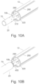
- FIG. 10 A shows a riveted fitting of an end of the transmission shaft
- FIG. 10 B shows a spline fitting of an end of the transmission shaft
- FIG. 11 shows a schematic representation of an exemplary power transmission system
- FIG. 12 shows a rod with fibres.
- FIGS. 1 A and 1 B show an example of a transmission shaft 100 ′ with a rod 1 extending between an input side 20 (first side) and an output side 30 (second side) of the transmission shaft 100 ′.
- the input side 20 is for inputting torque to the transmission shaft 100 ′ and the output side 30 is outputting torque from the transmission shaft 100 ′.
- Torque can also be delivered in the other direction via the transmission shaft, in which case the first and second sides are swapped over.
- the input side 20 and the output side 30 may comprise flexible couplings 70 , for example, comprising a universal joint 60 or other form of torque connector, that are connected to a first end 1 c and a second end 1 c of the rod 1 .
- the transmission shaft 100 ′ may be coupled with two such flexible couplings to provide a power transmission shaft assembly for a drive train.
- the flexible couplings 70 may be identical on the input side 20 and output side 30 .
- the flexible couplings 70 may comprise a fitting 80 on one side of the universal joint 60 , and a torque plate 90 and connector mount 110 on the other (rod) side of the universal joint 60 , for example as shown, though other arrangements are possible.
- the flexible couplings can be used to connect the input side 2 and the output side 3 of the transmission shaft 100 ′, respectively, to other components in the drive train or transmission system.
- fitting 80 at the input side 2 can receive torque from a component 150 upstream of the fitting 80 such as a motor, gearbox or power transmission shaft and couple that torque through the universal joint 60 and the torque plate 90 and connector mount 110 into the first end 1 b of the rod 1 .
- a second torque connector 70 comprising a torque plate 90 , a universal joint 60 and a fitting 80 , can receive torque from the second end 1 b of the rod 1 and output the torque to a component 160 downstream of the transmission shaft 100 ′, for example, an actuator, a gearbox, generator, or other component requiring a rotational drive.
- the flexible coupling 60 may comprise any type of coupling for example self-aligning bearings.
- the rod 1 extends longitudinally from the first end 1 b to the second end 1 c for transferring the torque between the input side 20 and the output side 30 of the transmission shaft 100 ′.
- the rod 1 additionally comprises a torsional compliant section 1 a , extending between the first end 1 b and the second end 1 c .
- the torsional compliant section 1 a may extend the full length between the wider diameter first end 1 b and the second end 1 c.
- the torsional compliant section 1 a is provided to allow the transmission shaft 100 ′ to respond to and to take up sudden spikes in torque.
- the rod 1 is compliant in a torsional direction to allow the shaft to twist and act as a spring to protect the other components of the transmission system.
- the rod 1 is typically a solid rod and the torsional compliant section 1 a is an extended section between the ends that is of reduced diameter, providing a spring-like torsional resilience to the transmission system.
- FIG. 1 A shows the transmission shaft 100 ′ in a neutral position.
- neutral position used herein, it is meant the position that the transmission shaft 100 ′ naturally adopts at rest as well as positions during normal use where the differences in torque between the first and second ends 1 b , 1 c are relatively small compared to a full working range of allowable deflection, e.g., when small oscillations within the rod 1 may be present.
- neutral position includes the condition where there is a minor amount of deflection along the rod 1 in accordance with normal operational tolerances at the lower end of the working range.
- FIG. 1 B shows the known transmission shaft 100 ′ in use when significant oscillations are experienced having an excessive amplitude, i.e., towards the upper end of a working range.
- oscillations may be experienced during use when harmonic resonance is encountered, but more particularly can be witnessed as a result of a component failing or jamming, such as a rotor blade being lost from an engine causing a rotor imbalance.
- a transmission shaft 100 ′ with a torsional compliant section 1 a is naturally more flexible and so will lack the lateral stiffness of a regular transmission shaft 100 ′, for example, which may comprise a tubular section of wider diameter having much greater lateral stiffness. As a result, the torsional compliant section 10 a is more susceptible to harmonic vibration.
- FIG. 2 shows a transmission shaft 100 that includes a rod 10 which comprises a first end 10 b connected to the input side 20 of the transmission shaft and a second end 10 c connected to the output side 30 of the transmission shaft 100 . Between the first and second ends, the rod 10 provides the transmission shaft 100 with a torsional compliant central section 10 a . Thus the rod 10 , through this torsional compliant section, sets the torsional stiffness of the transmission shaft 100 .
- the rod 10 has a cross-section which extends in a longitudinal direction to define a central core 200 for transmitting torque directly from the first end 10 b to the second end 10 c . This is seen more easily with reference to FIGS. 3 A through to 10 B.
- the cross-section also defines a radially outer section 270 comprising a plurality ribs 210 which extend radially and longitudinally from an outer periphery 260 of the central core 200 . These ribs 210 are for increasing transverse stiffness of the rod 10 .
- the ribs 210 are essentially “decoupled” from the torque transmission, in the sense that there is no direct transmission of torque between the first end 10 b and the second end 10 c through the ribs 210 . More particularly there may be no direct transmission of torque, as far as possible, between the input side 20 and the first end 10 b through the ribs 210 and/or between the output side 30 and the second end 10 c through the ribs 210 .
- the central core 200 of the rod 10 is configured to transmit torque from the input side 20 to the output side 30 of the transmission shaft 100 through the first end 10 b and second end 10 c of the rod 10 .
- the central core 200 may be responsible for transmitting substantially all of the torque, for example, more than 90% of the torque, may be more than 95% of the torque, more than 98% of the torque, or even more than 99% of the torque.
- the cross-section of the torsionally compliant section 10 a of the rod 10 also defines a radially outer section 270 , which may extend a majority of the length of the rod 10 .
- the radially outer section 270 comprises a plurality of stiffening ribs 210 extending from the outer periphery 260 of the central core 200 of the rod 10 . These ribs 210 may be continuous and extend along the entire length of the rod 10 . Alternatively they may include breaks or may only extend along a portion of the rod 10 .
- the ribs 210 are configured to resist lateral deflection in the rod 10 during operation through vibration or sudden spikes of torque, and have no significant effect on the torsional compliance of the central core 200 of the rod 10 (e.g., less than 10%, may be less than 5%, less than 2%, or even less than 1% effect). This allows the rod 10 to provide a desired degree of torsional compliance while also limiting the amount of transverse deflection that can result from vibrational oscillations and deflection in the rod 10 .
- the central core 200 , 300 may have an outer diameter dimension which is more than twice the lateral thickness of any or each rib. It may have an outer diameter dimension of three, four, five, six or more times the lateral thickness of the ribs 210 .
- the core is configured to provide desired torsional compliance characteristics for the transmission shaft 100 in a dedicated part of the rod 10 having a generally cylindrical form.
- the ribs 210 may appear elongate in a radial direction when viewed in transverse cross-section. For example, they may extend radially a distance of three times longer than they are wide or more, optionally the radial distance (height) may be four, five, six times, or more the lateral width dimension.
- the ribs 210 may be arranged symmetrically about an axis of the rod 10 . For example, for every rib 210 , there may be a diametrically opposed rib 210 arranged on the other side of the rod 10 .
- ribs 210 There maybe three or more ribs 210 , for example, four, six, eight or ten ribs 210 , symmetrically arranged around the central core 200 .
- the ribs 210 may include a flange 220 , 240 , for example, at a distal end of the respective rib 210 , to improve the lateral stiffness of the transmission shaft 100 .
- a flange 220 , 240 may also be provided at other locations on the ribs 210 to improve the lateral stiffness of the transmission shaft 100 .
- Such flanges 220 , 240 may extend laterally from the radial extension of the rib 210 , for example, in a straight, tangential configuration 240 or a curved, circumferential configuration 220 . In such an embodiment, flanges 220 , 240 may be provided on each rib 210 or on every other rib 210 .
- the laterally extending flange 220 , 240 of one rib 210 should be spaced from the laterally extending flange 220 , 240 of an adjacent rib 210 such that an axially-extending gap 280 is present between the flanges 220 , 240 under all working torsional loads. In this way, a load path cannot develop between the flanges 220 , 240 .
- the ribs 210 of the radially outer section 270 of the rod 10 may increase the lateral stiffness of the transmission shaft 100 by more than 10%, 25%, 50%, 75%, 90%, or even more than 100%.
- the amount of deflection in the transmission shaft 100 during oscillations is reduced significantly. It may reduce the oscillation amplitude by 50% or more, for example, by more than 75%. In some embodiments the oscillation amplitude of the transmission shaft 100 is reduced by up to 90% compared to a transmission shaft 100 having a similar central core 200 but without the associated ribs 210 .
- the ribs 210 may be made of the same material as the rod 10 , ensuring compatibility with the rod 10 .
- the rod 10 may be formed by extrusion or pultrusion to produce a rod 10 having ribs 210 that is made of a uniform material, for example, a lightweight metal alloy or a composite material. It would also be possible to make the ribs 210 from a material with a higher stiffness than the torsional compliant section of the rod 10 . For example, they may be reinforced with fibres in a different orientation or made from a stiffer aluminium alloy, steel, superalloy material, etc., than the central core 200 of the rod 10 . Such processing may be achievable through three-dimensional fabrication techniques or through known hardening techniques.
- oscillation amplitudes may be reduced below 30 mm, or even less than 25 mm on such a transmission shaft 100 subjected to a HLSD curve P (+/ ⁇ 10G n ⁇ pk) of the DO160G test.
- the rod 10 comprising the torsional compliant section 10 a and the radially outer section 270 may be manufactured by extrusion.
- the extrusion apparatus can be provided with a die corresponding in shape to the intended cross-section of the rod 10 .
- Extrusion also offers the possibility to produce the central core 200 with a hollow centre (central hollow 300 ), as a way to reduce the overall weight of the rod 10 .
- the rod 10 may be manufactured by pultrusion, for example, where fibres are pulled through a die drawing matrix material with them to produce a profiled product with fibres running along the centre.
- Such techniques can produce accurate cross-sections for a rod 10 which has multiple ribs 210 and flanges 220 , 240 as well as a central core 200 .
- the rod 10 can be machined afterwards to remove portions of ribs 210 , for example, to decouple the ribs 210 as a primary load path for transmitting torque from the first end 10 b to the second and of the rod, or to tune the vibrational characteristics of the rod.
- the central core 200 and radially outer section 270 may be formed as one piece for ease of production, the ribs 210 could also be formed separately and connected to the central core 200 .
- the rib connections with the central core 200 could be made by a suitable fusion technique, for example, welding, brazing, soldering, an adhesive or any other type of joining method.
- FIG. 3 A shows a first exemplary cross section of the central section 10 a of the rod 10 .
- the cross section comprises a central core 200 which is circular in cross-section.
- the central core 200 of the rod 10 may be other profiles, for example, the central core 200 may include fillet portions or maybe more angular in the spaces between the ribs 210 .
- the input side 20 and output side 30 of the transmission shaft 100 are coupled to the first end 10 b and second end 10 c of the rod 10 respectively through a first circumferentially extending interface and a second circumferentially extending interface 290 (see FIGS.
- the mechanical interface may be between a first portion of a circumferential outer surface 260 (outer periphery) of the central core 200 and a circumferential inner surface of a fitting providing the first side 20 .
- a second portion of the circumferential outer surface 260 of the central core 200 may provide a similar mechanical interface with a circumferential inner surface of a fitting providing the second side 30 of the transmission shaft 100 .
- the ribs 210 in addition to extending along the length of the torsional compliant section (i.e. longitudinally), extend in a radial direction to the flanges 220 , 240 , to provide an outer dimension of the rod 10 .
- the rod may comprise fibres 1001 extending longitudinally the entire length of the rod as shown in FIG. 12 .
- FIG. 3 A comprises four ribs 210 arranged to stiffen the rod, each separated by 90 degrees around the circumference of the central core 200 . It will be appreciated that any number of ribs 210 can be used.
- the ribs 210 may be arranged as pairs, with one rib 210 arranged diametrically opposed to the other rib 210 of the pair.
- each rib may be connected to a laterally extending flange 220 , for example, in the form of a circumferentially extending flange.
- Each circumferentially extending flange 220 may follow around an arc of the circumference of the outer section 270 .
- the outer circumference is not continuous.
- each circumferentially extending flange 220 is of equal width and separate, and so the circumferential spacing between each arc portion is also equal.
- the axially extending gaps between the flanges 220 , 240 helps to ensure that torque is not transmitted through the flanges 220 , 240 (via the ribs) from the first end 10 b to the second end 10 c of the rod, and instead the central core 200 remains the primary load path for the torsional forces.
- Circumferentially extending flanges 220 as compared to tangentially extending flanges 240 offer benefits in terms of aerodynamic operation.
- the laterally extending flange can be in the form of a tangentially extending flange 240 , which might offer benefits in terms of ease of construction.
- Each laterally extending flange 220 , 240 is also depicted at the radially outermost end of the rib 210 .
- a circumferentially or tangentially extending flange may be formed at any distance along the rib 210 .
- the flange may be at 25%, 50%, or 75% the distance between the outer periphery 260 of the central core 200 and the radially outermost end of the rib 210 .
- laterally extending flanges 220 , 240 may cover a larger portion of the circumference of the rod 10 than others, meaning that the circumferential spacing 280 between each laterally extending flange 220 , 240 may also differ.
- the sizing of each laterally extending flange 220 , 240 will be determined by the expected load distribution in the rod 10 .
- the cross-section of the rod 10 may be uniform in diameter.
- the diameter of the central core 200 , the length of the ribs 210 and the circumferentially extending flanges 220 , 240 may vary along the length of the rod 10 .
- Increasing the diameter of the central core 200 of the rod 10 will increase the torsional stiffness and reduce the torsional compliance of the rod 10 , and vice versa.
- increasing the length of the ribs 210 in the radial direction will further increase the lateral stiffness of the rod. Adjustments, e.g., through machining or other forming processes, may be made to the profile to help tune the vibrational characteristics of the rod 10 and the transmission shaft 100 .
- the ribs 210 are positioned so that they increase the lateral stiffness of the rod 10 when in use, but do not significantly affect the torsional compliance of the central core 200 of the rod 10 . It will be appreciated that the torsional compliance of the rod 10 as a whole will also be reduced slightly due to the presence of the material of the ribs 210 , however this can be taken into account when designing the transmission shaft 100 to have particular levels of torsional compliance, e.g., as required to smooth out occasional torque spikes which can be anticipated during the operation of the component.
- the outer diameter dimension may be between 0.05% and 1% smaller, optionally less than 0.5% smaller, than for a rod 10 having no ribs 210 that is able to provide the same torsional stiffness.
- the present disclosure also provides a method of transmitting torque along a transmission shaft 100 , the transmission shaft 100 comprising a rod 10 with a central core 200 to provide the transmission shaft 100 with a torsional compliant section having a desired torsional stiffness and a plurality of longitudinally and radially extending ribs 210 arranged about the central core 200 to improve the transverse stiffness of the rod, wherein the transmission shaft 100 is configured so that the ribs 210 are, as far as possible, decoupled from transmitting torque between an input side 20 and an output side 30 of the transmission shaft 100 , the method comprising introducing torque into the rod 10 from the input side through the central core 200 only, the rod 10 transmitting the torque along the central core 200 directly to the output side 30 of the transmission side of the transmission shaft 100 .
- the central section 10 a of the rod 10 with the cross section shown in FIG. 3 A can be formed by extrusion or pultrusion. This would enable the part to be made as one piece.
- the profiled portion of the rod 10 with the cross section of FIG. 3 A may then be connected to a first shaft portion and a second shaft portion at the ends of the rod, for example, through a mechanical connection or through being fused or bonded together to create a mechanical interface.
- the mechanical interface may have a radial extent corresponding to the cross-sectional profile of the central core 200 so that torque is transmitted directly into the central core 200 rather than the ribs 210 .
- the ribs 210 may be machined to remove the ribs 210 to provide a first shaft portion and a second shaft portion at the ends of the rod 10 without ribs 210 or with the ribs 210 decoupled.
- the first and second shaft portions can be connected to flexible couplings providing the input side 20 and the output side 30 of the transmission shaft 100 where the torque is inputted and outputted from the transmission shaft 100 .
- the flexible couplings 70 can be arranged to deliver the torque through a circumferentially extending interface 290 with the rod 10 , for example, in the form of a male/female connection comprising bonded or fused parts, and/or some form of mechanical connection, such as rivets or splined surfaces (see FIGS. 10 A and 10 B ).
- FIG. 3 B shows another exemplary cross-section for the central section 10 a of the rod 10 10 .
- the cross section shown in FIG. 3 B matches that of FIG. 3 A in that it also comprises a central core 200 with a required degree of torsional compliance, four ribs and a circumferential flange connected to each rib.
- the central core 300 of the cross section shown in FIG. 3 B comprises a void 300 , rather than the solid construction shown in FIG. 3 A .
- a hollow central core 300 will have a higher torsional compliance (lower torsional stiffness) compared to a solid central core of the same diameter, but less overall strength. It also requires a more complex mandrel for the extrusion or pultrusion operation.
- a benefit of the hollow central core 300 is that the rod 10 will require less material, hence reducing costs and also making the transmission shaft 100 lighter, leading to improvements in efficiency of the aircraft on which the transmission shaft 100 is employed.
- FIGS. 4 A and 4 B show further exemplary cross-sections of the rod 10 .
- FIG. 4 A comprises a central core 200 , eight ribs 210 extending from the peripheral surface of the central core and circumferentially extending flanges 220 at the outer end of each rib 210 .
- the stiffening ribs 210 are separated by 45 degrees.
- the cross section of the rod 10 shown in FIG. 4 A differs from the cross section shown in FIG. 3 A in that there are four additional ribs 210 and corresponding circumferentially extending flanges 220 .
- ribs 210 also further reduces the torsional compliance of the rod 10 as a whole. There is therefore a trade-off between providing a rod 10 that is sufficiently stiff in a transverse direction, while still providing the required torsional compliance. Experimentation or finite analysis may be conducted with different central core diameters, rib radial length, and numbers of ribs 210 to determine the best combination for torsional stiffness, transverse stiffness, weight considerations and other factors.
- the cross section shown in FIG. 4 B corresponds to the cross section shown in FIG. 4 A , except that the central core 200 is hollow, similar to FIG. 3 B .
- the reduced torsional compliance in the rod 10 from the additional ribs 210 may be offset, at least in part, by making the central core 200 hollow.
- FIG. 5 A shows another cross section of the central section 10 a of the rod 10 of the present disclosure.
- FIG. 5 A comprises a solid central core 200 and four ribs 210 extending from the outer periphery 260 of the central core 200 , as in FIG. 3 A .
- the cross section in FIG. 5 A further includes laterally extending flanges 240 at the radially outer point of each stiffening rib, this time presented as tangentially extending flanges 240 .
- the tangentially extending flanges 240 in FIG. 5 A are straight (planar), as opposed to the curved (arcuate) circumferentially extending flanges 220 shown in FIG. 3 A .
- the circumferentially extending flanges 220 together form an overall circular cross section (providing the appearance of a cylindrical rod), whereas in FIG. 5 A they collectively form an overall square cross section (providing the appearance of a square bar), each of these arrangements comprising longitudinally extending gaps 280 between the flanges 240 .
- the straight, tangentially extending flanges may be simpler to manufacture and also may provide additional stiffness to the rod 10 compared to the circumferentially extending flanges 220 , providing more of an I-beam effect.
- the circumferentially extending flanges 220 can offer benefits in terms of improved aerodynamics. Thus one form may be more suited for a particular situation than the other.
- the tangentially extending flanges 240 can be positioned at any point along the radial length of the ribs 210 . Additionally, each of the tangentially extending flanges 240 can be of equal size, or if desired, there may be differences in size, e.g. alternate pairs of ribs 210 and flanges, so the spacing between them may also different in size.
- FIG. 5 B shows another cross section of the rod 10 which corresponds to the cross section in FIG. 5 A but the central core 200 comprises a central void 300 and is hollow instead of solid, similar to the embodiment in FIG. 3 B .
- FIGS. 6 A and 6 B show further cross sections of the rod 10 . Both cross sections show a central core 200 and eight ribs 210 extending from the outer periphery 260 of the central core 200 .
- the central core 200 in FIG. 6 A is solid, while the central core 200 in FIG. 6 B comprises a central void 300 and is hollow. Similar to FIGS. 5 A and 5 B the laterally extending flanges 240 are straight, as opposed to the curved, circumferentially extending flanges in FIGS. 4 A and 4 B .
- FIGS. 7 A- 8 B show further exemplary cross sections of the central section 10 a of the rod 10 , each including a central core and symmetrically arranged, radially extending ribs 210 .
- the cross sections of FIGS. 7 A and 8 A have a solid central core 200
- the cross sections of FIGS. 7 B and 8 B have a hollow central core 200 comprising a central void 300 .
- the cross sections of FIGS. 7 A and 7 B have four ribs 210
- the cross sections of FIGS. 8 A and 8 B each have eight ribs 210 .
- circumferentially extending flanges 220 are not present at any point along the stiffening ribs 210 . This may be beneficial in some scenarios in that it leads to material and rotational weight savings.
- FIGS. 9 A and 9 B show other exemplary embodiments, with a central core 200 being either solid or hollow and ribs 210 extending from the central core 200 to laterally (circumferentially) extending flanges 220 .
- a central core 200 being either solid or hollow and ribs 210 extending from the central core 200 to laterally (circumferentially) extending flanges 220 .
- the fillet portion 260 strengthens the connection between the stiffening ribs 250 and the central core 300 by reducing stress concentrations. This means that the stiffening ribs 210 may be made of a lighter material without failing.
- the fillet portion 260 may also increase the lateral stiffness of the rod 10 and reduce the torsional compliance of the rod 10 but this can be factored into the design of the rod 10 for the transmission shaft 100 .
- fillet portions 260 shown in FIGS. 9 A and 9 B may be applied to any of the preceding cross sections. There may be more or less than four ribs 210 , and the laterally extending flanges 220 , 240 may be straight or curved depending on the design requirements of the rod 10 and the overall torsional response required of the transmission shaft 100 .
- the ends 10 b , 10 c will also be hollow. However, the ends 10 b , 10 c may be solid, even if the core 200 is hollow. Similarly, if the central core 200 is solid, the ends 10 b , 10 c may be hollow, or the ends 10 b , 10 c may also be hollow.
- FIGS. 10 A and 10 B show two exemplary embodiments of the circumferential coupling arrangement between the first end 10 b and the input side 20 .
- a similar arrangement may be provided between the second end 10 c and the output side 30 .
- FIG. 10 A the flexible coupling 70 is shown coupled to the first end 10 b of the rod 10 using rivets 310 , screws, bolts or other types of fastener.
- the torsional forces are transmitted from the fitting across the circumferential interface 290 between the flexible coupling 70 and the circumferential surface of the first end 10 b of the rod 10 (i.e., in a location ahead of the ribs 210 ).
- the torsional compliant central section 10 a is not coupled to the flexible coupling 70 by rivets 300 or other fastener that can transmit torsional forces; only the first end 10 b extending form the central core 200 of the torsional compliant central section 10 a is riveted to the flexible coupling 70 .
- FIG. 10 B shows the fitting 80 as a splined fitting engaging a plurality of splines 400 provided around the circumference of the central core 200 at the first end 10 b.
- the end surfaces 320 of the ribs 210 are spaced from the circumferentially extending interface between the flexible coupling 70 of the input side 20 and the first end 10 b of the rod 10 .
- ends of the rod 10 may be glued, welded or otherwise fused, or press-fitted.
- Each of the fitting types may be used for both the solid core 200 and the hollow core.
- both the first end 10 b and second end 10 c of the rod 10 can be connected to the flexible coupling 70 by the same method.
- they may use different forms of connection, for example the first end 10 b may be connected to the flexible coupling 70 by rivets 310 and the second end 10 c may be connected to the flexible coupling by a spline fitting 400 .
Landscapes
- Engineering & Computer Science (AREA)
- General Engineering & Computer Science (AREA)
- Mechanical Engineering (AREA)
- Automation & Control Theory (AREA)
- Aviation & Aerospace Engineering (AREA)
- Ocean & Marine Engineering (AREA)
- Health & Medical Sciences (AREA)
- Oral & Maxillofacial Surgery (AREA)
- Shafts, Cranks, Connecting Bars, And Related Bearings (AREA)
Abstract
Description
Claims (14)
Applications Claiming Priority (3)
| Application Number | Priority Date | Filing Date | Title |
|---|---|---|---|
| EP19461531 | 2019-05-02 | ||
| EP19461531.6 | 2019-05-02 | ||
| EP19461531.6A EP3734091B1 (en) | 2019-05-02 | 2019-05-02 | Vibration resistant torsionally compliant transmission shaft |
Publications (2)
| Publication Number | Publication Date |
|---|---|
| US20200347875A1 US20200347875A1 (en) | 2020-11-05 |
| US11566657B2 true US11566657B2 (en) | 2023-01-31 |
Family
ID=66429304
Family Applications (1)
| Application Number | Title | Priority Date | Filing Date |
|---|---|---|---|
| US16/697,485 Active 2040-12-30 US11566657B2 (en) | 2019-05-02 | 2019-11-27 | Vibration resistant torsionally compliant transmission shaft |
Country Status (2)
| Country | Link |
|---|---|
| US (1) | US11566657B2 (en) |
| EP (1) | EP3734091B1 (en) |
Cited By (1)
| Publication number | Priority date | Publication date | Assignee | Title |
|---|---|---|---|---|
| US20220348308A1 (en) * | 2021-05-03 | 2022-11-03 | Airbus Operations Gmbh | Wing for an aircraft |
Families Citing this family (2)
| Publication number | Priority date | Publication date | Assignee | Title |
|---|---|---|---|---|
| CN112324791A (en) * | 2020-11-27 | 2021-02-05 | 吉林聚鑫碳纤维科技有限公司 | Carbon fiber composite material transmission shaft tube joint structure |
| US12607232B2 (en) | 2023-03-27 | 2026-04-21 | Goodrich Corporation | Flexible metallic coupling for drive shafts made by additive manufacturing |
Citations (14)
| Publication number | Priority date | Publication date | Assignee | Title |
|---|---|---|---|---|
| US1339970A (en) * | 1919-12-24 | 1920-05-11 | Jr Thomas E Murray | Method of producing longitudinal ribs on the exteriors of tubes |
| US2000997A (en) * | 1932-04-13 | 1935-05-14 | Peter F Sharpe | Universal shaft connection |
| US2822677A (en) * | 1955-12-27 | 1958-02-11 | Ingersoll Rand Co | Spring holder |
| US3869877A (en) * | 1971-06-03 | 1975-03-11 | George R Brahler | Drive shaft |
| DE4010901A1 (en) | 1990-04-04 | 1991-10-17 | Gkn Automotive Ag | Drive shaft for motor vehicle |
| US5894753A (en) * | 1996-10-04 | 1999-04-20 | Lemforder Nacam | Method of producing splines on a shaft |
| US20120001397A1 (en) | 2010-07-01 | 2012-01-05 | The Pullman Company | Extruded torque rods |
| US9527368B2 (en) | 2012-07-03 | 2016-12-27 | Pantero Technologies Inc. | Semi-independent suspension system for a low-floor vechicle |
| EP3128196A1 (en) | 2015-08-04 | 2017-02-08 | The Boeing Company | Torque tube assemblies for use with aircraft high lift devices |
| CN206111820U (en) | 2016-07-04 | 2017-04-19 | 郑州市东鼎干燥设备有限公司 | Bending resistance transmission shaft |
| US20170191559A1 (en) | 2016-01-06 | 2017-07-06 | Hamilton Sundstrand Corporation | Tuned rat driveshaft |
| WO2018050812A1 (en) | 2016-09-15 | 2018-03-22 | Jaguar Land Rover Limited | Driveshaft tube |
| US10531610B2 (en) * | 2016-03-21 | 2020-01-14 | Andreas Stihl Ag & Co. Kg | Guard tube for supporting a drive shaft of a hand-guided power tool |
| US11020827B2 (en) * | 2018-03-08 | 2021-06-01 | Steering Solutions Ip Holding Corporation | Torsion bar active length control and method of manufacturing |
-
2019
- 2019-05-02 EP EP19461531.6A patent/EP3734091B1/en active Active
- 2019-11-27 US US16/697,485 patent/US11566657B2/en active Active
Patent Citations (15)
| Publication number | Priority date | Publication date | Assignee | Title |
|---|---|---|---|---|
| US1339970A (en) * | 1919-12-24 | 1920-05-11 | Jr Thomas E Murray | Method of producing longitudinal ribs on the exteriors of tubes |
| US2000997A (en) * | 1932-04-13 | 1935-05-14 | Peter F Sharpe | Universal shaft connection |
| US2822677A (en) * | 1955-12-27 | 1958-02-11 | Ingersoll Rand Co | Spring holder |
| US3869877A (en) * | 1971-06-03 | 1975-03-11 | George R Brahler | Drive shaft |
| DE4010901A1 (en) | 1990-04-04 | 1991-10-17 | Gkn Automotive Ag | Drive shaft for motor vehicle |
| US5894753A (en) * | 1996-10-04 | 1999-04-20 | Lemforder Nacam | Method of producing splines on a shaft |
| US20120001397A1 (en) | 2010-07-01 | 2012-01-05 | The Pullman Company | Extruded torque rods |
| US9527368B2 (en) | 2012-07-03 | 2016-12-27 | Pantero Technologies Inc. | Semi-independent suspension system for a low-floor vechicle |
| EP3128196A1 (en) | 2015-08-04 | 2017-02-08 | The Boeing Company | Torque tube assemblies for use with aircraft high lift devices |
| US20170191559A1 (en) | 2016-01-06 | 2017-07-06 | Hamilton Sundstrand Corporation | Tuned rat driveshaft |
| US10295042B2 (en) * | 2016-01-06 | 2019-05-21 | Hamilton Sundstrand Corporation | Tuned RAT driveshaft |
| US10531610B2 (en) * | 2016-03-21 | 2020-01-14 | Andreas Stihl Ag & Co. Kg | Guard tube for supporting a drive shaft of a hand-guided power tool |
| CN206111820U (en) | 2016-07-04 | 2017-04-19 | 郑州市东鼎干燥设备有限公司 | Bending resistance transmission shaft |
| WO2018050812A1 (en) | 2016-09-15 | 2018-03-22 | Jaguar Land Rover Limited | Driveshaft tube |
| US11020827B2 (en) * | 2018-03-08 | 2021-06-01 | Steering Solutions Ip Holding Corporation | Torsion bar active length control and method of manufacturing |
Non-Patent Citations (1)
| Title |
|---|
| European Search Report for European Application No. 19461531.6, International Filing Date May, 2 2019, dated Nov. 15, 2019, 11 pages. |
Cited By (2)
| Publication number | Priority date | Publication date | Assignee | Title |
|---|---|---|---|---|
| US20220348308A1 (en) * | 2021-05-03 | 2022-11-03 | Airbus Operations Gmbh | Wing for an aircraft |
| US11970262B2 (en) * | 2021-05-03 | 2024-04-30 | Airbus Operations Gmbh | Aircraft wing and connection assembly for a high lift assembly |
Also Published As
| Publication number | Publication date |
|---|---|
| EP3734091B1 (en) | 2022-01-26 |
| EP3734091A1 (en) | 2020-11-04 |
| US20200347875A1 (en) | 2020-11-05 |
Similar Documents
| Publication | Publication Date | Title |
|---|---|---|
| US11566657B2 (en) | Vibration resistant torsionally compliant transmission shaft | |
| US11015594B2 (en) | Systems and method for use of single mass flywheel alongside torsional vibration damper assembly for single acting reciprocating pump | |
| JP5467877B2 (en) | Apparatus and coupling method for coupling vanes to turbomachine rotor shaft | |
| US7959512B2 (en) | Flexible disk, a flexible coupling provided with such a flexible disk, a mounting flange provided with such a flexible coupling, and a transmission shaft fitted with such a mounting flange | |
| CN107061475B (en) | Tuned ram air turbine drive shaft | |
| CN102155268A (en) | Apparatus and method for a low distortion weld for rotors | |
| US11396904B2 (en) | Composite drive shafts | |
| US7918739B2 (en) | Transmission joint | |
| US20170082137A1 (en) | Driveshaft for a rotary system | |
| EP2778445B1 (en) | shaft for gearbox systems to limit wear and corrosion | |
| RU2169876C2 (en) | Flanged joint unit | |
| SE541072C2 (en) | Driveshaft assembly and method for its production | |
| US12319136B2 (en) | Carbon composite tube yoke | |
| RU2263828C1 (en) | Connecting unit for members of machines | |
| EP2925644A1 (en) | Chain conveyor device | |
| EP3677801A1 (en) | Transmission shaft | |
| RU2341693C2 (en) | Machine components joint assembly | |
| CN219975168U (en) | a coupling | |
| RU218920U1 (en) | Coupling | |
| RU2802378C1 (en) | Carbon composite pipe fork | |
| US20250198464A1 (en) | Automotive drive shaft modular connector | |
| RU2293225C2 (en) | Joint | |
| US20210396276A1 (en) | Torsionally Elastic Shaft Joint and Method of Making the Same | |
| US8485908B2 (en) | Flexible coupler | |
| WO2026027227A1 (en) | Torsionally elastic shaft coupling |
Legal Events
| Date | Code | Title | Description |
|---|---|---|---|
| AS | Assignment |
Owner name: UTC AEROSPACE SYSTEMS WROCLAW SP. Z O.O., POLAND Free format text: ASSIGNMENT OF ASSIGNORS INTEREST;ASSIGNORS:KIELBOWICZ, DARIUSZ;KRULAK, MACIEJ;REEL/FRAME:051130/0119 Effective date: 20190626 Owner name: GOODRICH CORPORATION, NORTH CAROLINA Free format text: ASSIGNMENT OF ASSIGNORS INTEREST;ASSIGNOR:UTC AEROSPACE SYSTEMS WROCLAW SP. Z O.O.;REEL/FRAME:051131/0977 Effective date: 20190904 |
|
| FEPP | Fee payment procedure |
Free format text: ENTITY STATUS SET TO UNDISCOUNTED (ORIGINAL EVENT CODE: BIG.); ENTITY STATUS OF PATENT OWNER: LARGE ENTITY |
|
| STPP | Information on status: patent application and granting procedure in general |
Free format text: APPLICATION DISPATCHED FROM PREEXAM, NOT YET DOCKETED |
|
| STPP | Information on status: patent application and granting procedure in general |
Free format text: DOCKETED NEW CASE - READY FOR EXAMINATION |
|
| STPP | Information on status: patent application and granting procedure in general |
Free format text: NON FINAL ACTION MAILED |
|
| STPP | Information on status: patent application and granting procedure in general |
Free format text: FINAL REJECTION MAILED |
|
| STPP | Information on status: patent application and granting procedure in general |
Free format text: RESPONSE AFTER FINAL ACTION FORWARDED TO EXAMINER |
|
| STPP | Information on status: patent application and granting procedure in general |
Free format text: ADVISORY ACTION MAILED |
|
| STPP | Information on status: patent application and granting procedure in general |
Free format text: RESPONSE AFTER FINAL ACTION FORWARDED TO EXAMINER |
|
| STPP | Information on status: patent application and granting procedure in general |
Free format text: NOTICE OF ALLOWANCE MAILED -- APPLICATION RECEIVED IN OFFICE OF PUBLICATIONS |
|
| STPP | Information on status: patent application and granting procedure in general |
Free format text: PUBLICATIONS -- ISSUE FEE PAYMENT VERIFIED |
|
| STCF | Information on status: patent grant |
Free format text: PATENTED CASE |