US11564858B2 - Walking assistance method and walking assistance apparatus performing the same - Google Patents
Walking assistance method and walking assistance apparatus performing the same Download PDFInfo
- Publication number
- US11564858B2 US11564858B2 US16/656,015 US201916656015A US11564858B2 US 11564858 B2 US11564858 B2 US 11564858B2 US 201916656015 A US201916656015 A US 201916656015A US 11564858 B2 US11564858 B2 US 11564858B2
- Authority
- US
- United States
- Prior art keywords
- value
- ratio
- user
- pressure
- driver
- Prior art date
- Legal status (The legal status is an assumption and is not a legal conclusion. Google has not performed a legal analysis and makes no representation as to the accuracy of the status listed.)
- Active, expires
Links
Images


Classifications
-
- A—HUMAN NECESSITIES
- A61—MEDICAL OR VETERINARY SCIENCE; HYGIENE
- A61H—PHYSICAL THERAPY APPARATUS, e.g. DEVICES FOR LOCATING OR STIMULATING REFLEX POINTS IN THE BODY; ARTIFICIAL RESPIRATION; MASSAGE; BATHING DEVICES FOR SPECIAL THERAPEUTIC OR HYGIENIC PURPOSES OR SPECIFIC PARTS OF THE BODY
- A61H3/00—Appliances for aiding patients or disabled persons to walk about
- A61H3/008—Appliances for aiding patients or disabled persons to walk about using suspension devices for supporting the body in an upright walking or standing position, e.g. harnesses
-
- A—HUMAN NECESSITIES
- A61—MEDICAL OR VETERINARY SCIENCE; HYGIENE
- A61H—PHYSICAL THERAPY APPARATUS, e.g. DEVICES FOR LOCATING OR STIMULATING REFLEX POINTS IN THE BODY; ARTIFICIAL RESPIRATION; MASSAGE; BATHING DEVICES FOR SPECIAL THERAPEUTIC OR HYGIENIC PURPOSES OR SPECIFIC PARTS OF THE BODY
- A61H3/00—Appliances for aiding patients or disabled persons to walk about
-
- A—HUMAN NECESSITIES
- A61—MEDICAL OR VETERINARY SCIENCE; HYGIENE
- A61H—PHYSICAL THERAPY APPARATUS, e.g. DEVICES FOR LOCATING OR STIMULATING REFLEX POINTS IN THE BODY; ARTIFICIAL RESPIRATION; MASSAGE; BATHING DEVICES FOR SPECIAL THERAPEUTIC OR HYGIENIC PURPOSES OR SPECIFIC PARTS OF THE BODY
- A61H1/00—Apparatus for passive exercising; Vibrating apparatus; Chiropractic devices, e.g. body impacting devices, external devices for briefly extending or aligning unbroken bones
-
- A—HUMAN NECESSITIES
- A61—MEDICAL OR VETERINARY SCIENCE; HYGIENE
- A61B—DIAGNOSIS; SURGERY; IDENTIFICATION
- A61B5/00—Measuring for diagnostic purposes; Identification of persons
- A61B5/103—Measuring devices for testing the shape, pattern, colour, size or movement of the body or parts thereof, for diagnostic purposes
- A61B5/1036—Measuring load distribution, e.g. podologic studies
- A61B5/1038—Measuring plantar pressure during gait
-
- A—HUMAN NECESSITIES
- A61—MEDICAL OR VETERINARY SCIENCE; HYGIENE
- A61B—DIAGNOSIS; SURGERY; IDENTIFICATION
- A61B5/00—Measuring for diagnostic purposes; Identification of persons
- A61B5/103—Measuring devices for testing the shape, pattern, colour, size or movement of the body or parts thereof, for diagnostic purposes
- A61B5/11—Measuring movement of the entire body or parts thereof, e.g. head or hand tremor or mobility of a limb
- A61B5/112—Gait analysis
-
- A—HUMAN NECESSITIES
- A61—MEDICAL OR VETERINARY SCIENCE; HYGIENE
- A61H—PHYSICAL THERAPY APPARATUS, e.g. DEVICES FOR LOCATING OR STIMULATING REFLEX POINTS IN THE BODY; ARTIFICIAL RESPIRATION; MASSAGE; BATHING DEVICES FOR SPECIAL THERAPEUTIC OR HYGIENIC PURPOSES OR SPECIFIC PARTS OF THE BODY
- A61H1/00—Apparatus for passive exercising; Vibrating apparatus; Chiropractic devices, e.g. body impacting devices, external devices for briefly extending or aligning unbroken bones
- A61H1/02—Stretching or bending or torsioning apparatus for exercising
- A61H1/0237—Stretching or bending or torsioning apparatus for exercising for the lower limbs
- A61H1/024—Knee
-
- A—HUMAN NECESSITIES
- A61—MEDICAL OR VETERINARY SCIENCE; HYGIENE
- A61H—PHYSICAL THERAPY APPARATUS, e.g. DEVICES FOR LOCATING OR STIMULATING REFLEX POINTS IN THE BODY; ARTIFICIAL RESPIRATION; MASSAGE; BATHING DEVICES FOR SPECIAL THERAPEUTIC OR HYGIENIC PURPOSES OR SPECIFIC PARTS OF THE BODY
- A61H1/00—Apparatus for passive exercising; Vibrating apparatus; Chiropractic devices, e.g. body impacting devices, external devices for briefly extending or aligning unbroken bones
- A61H1/02—Stretching or bending or torsioning apparatus for exercising
- A61H1/0237—Stretching or bending or torsioning apparatus for exercising for the lower limbs
- A61H1/0244—Hip
-
- A—HUMAN NECESSITIES
- A61—MEDICAL OR VETERINARY SCIENCE; HYGIENE
- A61H—PHYSICAL THERAPY APPARATUS, e.g. DEVICES FOR LOCATING OR STIMULATING REFLEX POINTS IN THE BODY; ARTIFICIAL RESPIRATION; MASSAGE; BATHING DEVICES FOR SPECIAL THERAPEUTIC OR HYGIENIC PURPOSES OR SPECIFIC PARTS OF THE BODY
- A61H1/00—Apparatus for passive exercising; Vibrating apparatus; Chiropractic devices, e.g. body impacting devices, external devices for briefly extending or aligning unbroken bones
- A61H1/02—Stretching or bending or torsioning apparatus for exercising
- A61H1/0237—Stretching or bending or torsioning apparatus for exercising for the lower limbs
- A61H1/0266—Foot
-
- B—PERFORMING OPERATIONS; TRANSPORTING
- B25—HAND TOOLS; PORTABLE POWER-DRIVEN TOOLS; MANIPULATORS
- B25J—MANIPULATORS; CHAMBERS PROVIDED WITH MANIPULATION DEVICES
- B25J19/00—Accessories fitted to manipulators, e.g. for monitoring, for viewing; Safety devices combined with or specially adapted for use in connection with manipulators
- B25J19/02—Sensing devices
-
- B—PERFORMING OPERATIONS; TRANSPORTING
- B25—HAND TOOLS; PORTABLE POWER-DRIVEN TOOLS; MANIPULATORS
- B25J—MANIPULATORS; CHAMBERS PROVIDED WITH MANIPULATION DEVICES
- B25J9/00—Programme-controlled manipulators
- B25J9/0006—Exoskeletons, i.e. resembling a human figure
-
- B—PERFORMING OPERATIONS; TRANSPORTING
- B25—HAND TOOLS; PORTABLE POWER-DRIVEN TOOLS; MANIPULATORS
- B25J—MANIPULATORS; CHAMBERS PROVIDED WITH MANIPULATION DEVICES
- B25J9/00—Programme-controlled manipulators
- B25J9/16—Programme controls
- B25J9/1628—Programme controls characterised by the control loop
- B25J9/163—Programme controls characterised by the control loop learning, adaptive, model based, rule based expert control
-
- B—PERFORMING OPERATIONS; TRANSPORTING
- B25—HAND TOOLS; PORTABLE POWER-DRIVEN TOOLS; MANIPULATORS
- B25J—MANIPULATORS; CHAMBERS PROVIDED WITH MANIPULATION DEVICES
- B25J9/00—Programme-controlled manipulators
- B25J9/16—Programme controls
- B25J9/1628—Programme controls characterised by the control loop
- B25J9/1633—Programme controls characterised by the control loop compliant, force, torque control, e.g. combined with position control
-
- A—HUMAN NECESSITIES
- A61—MEDICAL OR VETERINARY SCIENCE; HYGIENE
- A61H—PHYSICAL THERAPY APPARATUS, e.g. DEVICES FOR LOCATING OR STIMULATING REFLEX POINTS IN THE BODY; ARTIFICIAL RESPIRATION; MASSAGE; BATHING DEVICES FOR SPECIAL THERAPEUTIC OR HYGIENIC PURPOSES OR SPECIFIC PARTS OF THE BODY
- A61H3/00—Appliances for aiding patients or disabled persons to walk about
- A61H2003/007—Appliances for aiding patients or disabled persons to walk about secured to the patient, e.g. with belts
-
- A—HUMAN NECESSITIES
- A61—MEDICAL OR VETERINARY SCIENCE; HYGIENE
- A61H—PHYSICAL THERAPY APPARATUS, e.g. DEVICES FOR LOCATING OR STIMULATING REFLEX POINTS IN THE BODY; ARTIFICIAL RESPIRATION; MASSAGE; BATHING DEVICES FOR SPECIAL THERAPEUTIC OR HYGIENIC PURPOSES OR SPECIFIC PARTS OF THE BODY
- A61H2201/00—Characteristics of apparatus not provided for in the preceding codes
- A61H2201/12—Driving means
- A61H2201/1207—Driving means with electric or magnetic drive
- A61H2201/1215—Rotary drive
-
- A—HUMAN NECESSITIES
- A61—MEDICAL OR VETERINARY SCIENCE; HYGIENE
- A61H—PHYSICAL THERAPY APPARATUS, e.g. DEVICES FOR LOCATING OR STIMULATING REFLEX POINTS IN THE BODY; ARTIFICIAL RESPIRATION; MASSAGE; BATHING DEVICES FOR SPECIAL THERAPEUTIC OR HYGIENIC PURPOSES OR SPECIFIC PARTS OF THE BODY
- A61H2201/00—Characteristics of apparatus not provided for in the preceding codes
- A61H2201/14—Special force transmission means, i.e. between the driving means and the interface with the user
- A61H2201/1463—Special speed variation means, i.e. speed reducer
-
- A—HUMAN NECESSITIES
- A61—MEDICAL OR VETERINARY SCIENCE; HYGIENE
- A61H—PHYSICAL THERAPY APPARATUS, e.g. DEVICES FOR LOCATING OR STIMULATING REFLEX POINTS IN THE BODY; ARTIFICIAL RESPIRATION; MASSAGE; BATHING DEVICES FOR SPECIAL THERAPEUTIC OR HYGIENIC PURPOSES OR SPECIFIC PARTS OF THE BODY
- A61H2201/00—Characteristics of apparatus not provided for in the preceding codes
- A61H2201/16—Physical interface with patient
- A61H2201/1602—Physical interface with patient kind of interface, e.g. head rest, knee support or lumbar support
- A61H2201/1628—Pelvis
-
- A—HUMAN NECESSITIES
- A61—MEDICAL OR VETERINARY SCIENCE; HYGIENE
- A61H—PHYSICAL THERAPY APPARATUS, e.g. DEVICES FOR LOCATING OR STIMULATING REFLEX POINTS IN THE BODY; ARTIFICIAL RESPIRATION; MASSAGE; BATHING DEVICES FOR SPECIAL THERAPEUTIC OR HYGIENIC PURPOSES OR SPECIFIC PARTS OF THE BODY
- A61H2201/00—Characteristics of apparatus not provided for in the preceding codes
- A61H2201/16—Physical interface with patient
- A61H2201/1602—Physical interface with patient kind of interface, e.g. head rest, knee support or lumbar support
- A61H2201/164—Feet or leg, e.g. pedal
- A61H2201/1642—Holding means therefor
-
- A—HUMAN NECESSITIES
- A61—MEDICAL OR VETERINARY SCIENCE; HYGIENE
- A61H—PHYSICAL THERAPY APPARATUS, e.g. DEVICES FOR LOCATING OR STIMULATING REFLEX POINTS IN THE BODY; ARTIFICIAL RESPIRATION; MASSAGE; BATHING DEVICES FOR SPECIAL THERAPEUTIC OR HYGIENIC PURPOSES OR SPECIFIC PARTS OF THE BODY
- A61H2201/00—Characteristics of apparatus not provided for in the preceding codes
- A61H2201/16—Physical interface with patient
- A61H2201/1602—Physical interface with patient kind of interface, e.g. head rest, knee support or lumbar support
- A61H2201/165—Wearable interfaces
-
- A—HUMAN NECESSITIES
- A61—MEDICAL OR VETERINARY SCIENCE; HYGIENE
- A61H—PHYSICAL THERAPY APPARATUS, e.g. DEVICES FOR LOCATING OR STIMULATING REFLEX POINTS IN THE BODY; ARTIFICIAL RESPIRATION; MASSAGE; BATHING DEVICES FOR SPECIAL THERAPEUTIC OR HYGIENIC PURPOSES OR SPECIFIC PARTS OF THE BODY
- A61H2201/00—Characteristics of apparatus not provided for in the preceding codes
- A61H2201/50—Control means thereof
- A61H2201/5007—Control means thereof computer controlled
-
- A—HUMAN NECESSITIES
- A61—MEDICAL OR VETERINARY SCIENCE; HYGIENE
- A61H—PHYSICAL THERAPY APPARATUS, e.g. DEVICES FOR LOCATING OR STIMULATING REFLEX POINTS IN THE BODY; ARTIFICIAL RESPIRATION; MASSAGE; BATHING DEVICES FOR SPECIAL THERAPEUTIC OR HYGIENIC PURPOSES OR SPECIFIC PARTS OF THE BODY
- A61H2201/00—Characteristics of apparatus not provided for in the preceding codes
- A61H2201/50—Control means thereof
- A61H2201/5058—Sensors or detectors
- A61H2201/5069—Angle sensors
-
- A—HUMAN NECESSITIES
- A61—MEDICAL OR VETERINARY SCIENCE; HYGIENE
- A61H—PHYSICAL THERAPY APPARATUS, e.g. DEVICES FOR LOCATING OR STIMULATING REFLEX POINTS IN THE BODY; ARTIFICIAL RESPIRATION; MASSAGE; BATHING DEVICES FOR SPECIAL THERAPEUTIC OR HYGIENIC PURPOSES OR SPECIFIC PARTS OF THE BODY
- A61H2201/00—Characteristics of apparatus not provided for in the preceding codes
- A61H2201/50—Control means thereof
- A61H2201/5058—Sensors or detectors
- A61H2201/5071—Pressure sensors
-
- A—HUMAN NECESSITIES
- A61—MEDICAL OR VETERINARY SCIENCE; HYGIENE
- A61H—PHYSICAL THERAPY APPARATUS, e.g. DEVICES FOR LOCATING OR STIMULATING REFLEX POINTS IN THE BODY; ARTIFICIAL RESPIRATION; MASSAGE; BATHING DEVICES FOR SPECIAL THERAPEUTIC OR HYGIENIC PURPOSES OR SPECIFIC PARTS OF THE BODY
- A61H2201/00—Characteristics of apparatus not provided for in the preceding codes
- A61H2201/50—Control means thereof
- A61H2201/5058—Sensors or detectors
- A61H2201/5079—Velocity sensors
-
- A—HUMAN NECESSITIES
- A61—MEDICAL OR VETERINARY SCIENCE; HYGIENE
- A61H—PHYSICAL THERAPY APPARATUS, e.g. DEVICES FOR LOCATING OR STIMULATING REFLEX POINTS IN THE BODY; ARTIFICIAL RESPIRATION; MASSAGE; BATHING DEVICES FOR SPECIAL THERAPEUTIC OR HYGIENIC PURPOSES OR SPECIFIC PARTS OF THE BODY
- A61H2201/00—Characteristics of apparatus not provided for in the preceding codes
- A61H2201/50—Control means thereof
- A61H2201/5058—Sensors or detectors
- A61H2201/5084—Acceleration sensors
-
- A—HUMAN NECESSITIES
- A61—MEDICAL OR VETERINARY SCIENCE; HYGIENE
- A61H—PHYSICAL THERAPY APPARATUS, e.g. DEVICES FOR LOCATING OR STIMULATING REFLEX POINTS IN THE BODY; ARTIFICIAL RESPIRATION; MASSAGE; BATHING DEVICES FOR SPECIAL THERAPEUTIC OR HYGIENIC PURPOSES OR SPECIFIC PARTS OF THE BODY
- A61H2205/00—Devices for specific parts of the body
- A61H2205/10—Leg
-
- A—HUMAN NECESSITIES
- A61—MEDICAL OR VETERINARY SCIENCE; HYGIENE
- A61H—PHYSICAL THERAPY APPARATUS, e.g. DEVICES FOR LOCATING OR STIMULATING REFLEX POINTS IN THE BODY; ARTIFICIAL RESPIRATION; MASSAGE; BATHING DEVICES FOR SPECIAL THERAPEUTIC OR HYGIENIC PURPOSES OR SPECIFIC PARTS OF THE BODY
- A61H2205/00—Devices for specific parts of the body
- A61H2205/12—Feet
-
- A—HUMAN NECESSITIES
- A61—MEDICAL OR VETERINARY SCIENCE; HYGIENE
- A61H—PHYSICAL THERAPY APPARATUS, e.g. DEVICES FOR LOCATING OR STIMULATING REFLEX POINTS IN THE BODY; ARTIFICIAL RESPIRATION; MASSAGE; BATHING DEVICES FOR SPECIAL THERAPEUTIC OR HYGIENIC PURPOSES OR SPECIFIC PARTS OF THE BODY
- A61H2230/00—Measuring physical parameters of the user
- A61H2230/08—Other bio-electrical signals
- A61H2230/10—Electroencephalographic signals
-
- A—HUMAN NECESSITIES
- A61—MEDICAL OR VETERINARY SCIENCE; HYGIENE
- A61H—PHYSICAL THERAPY APPARATUS, e.g. DEVICES FOR LOCATING OR STIMULATING REFLEX POINTS IN THE BODY; ARTIFICIAL RESPIRATION; MASSAGE; BATHING DEVICES FOR SPECIAL THERAPEUTIC OR HYGIENIC PURPOSES OR SPECIFIC PARTS OF THE BODY
- A61H2230/00—Measuring physical parameters of the user
- A61H2230/60—Muscle strain, i.e. measured on the user, e.g. Electromyography [EMG]
-
- A—HUMAN NECESSITIES
- A61—MEDICAL OR VETERINARY SCIENCE; HYGIENE
- A61H—PHYSICAL THERAPY APPARATUS, e.g. DEVICES FOR LOCATING OR STIMULATING REFLEX POINTS IN THE BODY; ARTIFICIAL RESPIRATION; MASSAGE; BATHING DEVICES FOR SPECIAL THERAPEUTIC OR HYGIENIC PURPOSES OR SPECIFIC PARTS OF THE BODY
- A61H2230/00—Measuring physical parameters of the user
- A61H2230/62—Posture
Definitions
- At least one example embodiment relates to a method and/or apparatus for assisting walking of a user.
- at least some example embodiments relate to a method and/or apparatus for providing an assistance torque to assist walking when a user walks.
- walking assistance apparatus for enhancing muscular strength of a human body, for example, for military purposes are being developed.
- Some example embodiments relate to a method of controlling a driver of a walking assistance apparatus.
- the method may include receiving a first pressure value and a second pressure value from a first pressure sensor and a second pressure sensor, respectively; calculating a ratio between the first pressure value and the second pressure value; determining a gain value based on the ratio; calculating an assistance torque value based on the ratio and the gain value; and controlling the driver of the walking assistance apparatus to output the assistance torque value.
- the first pressure sensor is associated with a first area of the walking assistance apparatus corresponding to a heel of a foot of a user
- the second pressure sensor is associated with a second area of the walking assistance apparatus corresponding to a ball of the foot of the user.
- the calculating the ratio includes calculating an initial ratio between the first pressure value and the second pressure value; and calculating a final ratio based on a value and the initial ratio.
- the calculating the ratio includes masking at least one of the first pressure value and the second pressure value to generate masked pressure values; and calculating a ratio between the masked pressure values.
- the masking includes comparing the second pressure value to a third threshold value, and the calculating the ratio between the masked pressure values includes setting the ratio as a default value in response to the second pressure value being less than the third threshold value.
- the masking further includes comparing the first pressure value to a first threshold value, and the calculating of the ratio between the masked pressure values further includes calculating the ratio between the first pressure value and the second pressure value in response to the first pressure value exceeding the first threshold value.
- the masking includes comparing the first pressure value to a second threshold value; and setting the first pressure value to be same as the second threshold value in response to the first pressure value being less than the second threshold value.
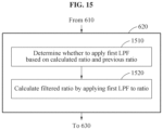
- the calculating the ratio between the first pressure value and the second pressure value includes determining whether to apply a first low-pass filter (LPF) to the ratio based on the ratio and a previous ratio to generate a determination result; and calculating a filtered ratio by applying the first LPF to the ratio based on the determination result.
- LPF low-pass filter
- the determining the gain value includes determining a target gain value among a plurality of gain values based on the ratio.
- the calculating the assistance torque value includes determining whether to apply a second LPF to the assistance torque value based on the assistance torque value and a previous assistance torque value to generate a determination result; and calculating a filtered assistance torque value by applying the second LPF to the assistance torque value based on the determination result.
- the controlling the driver includes setting an output delay time associated with applying the assistance torque value; and controlling the driver to delay outputting the assistance torque value by the delay time.
- controlling the driver includes controlling the driver based on an additional assistance torque pattern in response to the assistance torque value being maintained within a range.
- the controlling the driver includes controlling the driver to flex and extend an ankle of a user of the walking assistance apparatus based on the additional assistance torque pattern.
- the first pressure sensor and the second pressure sensor are associated with a sole of a foot of a first leg of a user, and the controlling of the driver includes controlling the driver such that the driver assists a second leg of the user, the second leg being different from the first leg.
- the controlling the driver includes controlling the driver of the walking assistance apparatus to output the assistance torque value to change an angle of an ankle of a user of the walking assistance apparatus.
- Some example embodiments relate to a non-transitory computer-readable medium including computer readable instructions that, when executed by a computer, configure the computer to perform a method of controlling a driver of a walking assistance apparatus.
- Some example embodiments relate to a walking assistance apparatus configured to provide an assistance torque to an ankle of a user.
- the walking assistance apparatus includes a memory configured to store a program; and a processor configured to execute the program to, receive a first pressure value and a second pressure value from a first pressure sensor and a second pressure sensor, respectively, calculate a ratio between the first pressure value and the second pressure value, determine a gain value based on the ratio, calculate an assistance torque value based on the ratio and the gain value, and control a driver to output the assistance torque value such that the assistance torque is provided to the ankle of the user by the driver.
- Some example embodiments relate to a walking assistance apparatus configured to assist walking of a user.
- the walking assistance apparatus includes a first pressure sensor and a second pressure sensor configured to generate a first pressure value and a second pressure value, respectively, by sensing pressure values of a sole of a foot of the user; a processor configured to, calculate a ratio between the first pressure value and the second pressure value, determine a gain value based on the ratio, and calculate an assistance torque value based on the ratio and the gain value; and a driver configured to output the assistance torque value.
- FIG. 1 illustrates a gait state according to at least one example embodiment
- FIG. 2 illustrates a transition between gait states according to at least one example embodiment
- FIG. 3 illustrates a similarity between a trajectory of a ratio between pressure values of a sole of a foot and a trajectory of an ankle assistance torque value according to at least one example embodiment
- FIG. 4 A is a perspective view illustrating an ankle-type walking assistance apparatus according to at least one example embodiment
- FIG. 4 B is a front view of a power distributor when a talocrural joint of a user is in a dorsi-flexion state according to at least one example embodiment
- FIG. 4 C is a side view of a walking assistance apparatus when a talocrural joint of a user is in a dorsi-flexion state according to at least one example embodiment
- FIG. 5 illustrates a structure of a walking assistance apparatus according to at least one example embodiment
- FIG. 6 is a flowchart illustrating a method of controlling a driver of a walking assistance apparatus according to at least one example embodiment
- FIG. 7 illustrates a first area and a second area, of a sole of a foot, in which a first pressure sensor and a second pressure sensor are disposed according to at least one example embodiment
- FIG. 8 is a flowchart illustrating an example of calculating a final ratio based on an initial ratio according to at least one example embodiment
- FIG. 9 illustrates a first pressure value, a second pressure value, and a ratio between the pressure values according to at least one example embodiment
- FIG. 10 is a flowchart illustrating an example of determining a ratio between masked pressure values according to at least one example embodiment
- FIG. 11 illustrates an example of masking at least one of a first pressure value and a second pressure value according to at least one example embodiment
- FIG. 12 is a flowchart illustrating an example of calculating a ratio between pressures in a state 0 and a state 1 according to at least one example embodiment
- FIG. 13 is a flowchart illustrating an example of calculating a ratio between pressures in a state 1 and a state 2 according to at least one example embodiment
- FIG. 14 illustrates a ratio from which noise of a pressure value is not removed and a ratio from which noise of a pressure value is removed according to at least one example embodiment
- FIG. 15 is a flowchart illustrating an example of calculating a filtered ratio using a first low-pass filter (LPF) according to at least one example embodiment
- FIG. 16 is a flowchart illustrating an example of calculating a filtered assistance torque value using a second LPF according to at least one example embodiment
- FIG. 17 illustrates a trajectory of a calculated assistance torque value according to at least one example embodiment
- FIG. 18 is a flowchart illustrating an example of controlling a driver to output a delayed assistance torque value according to at least one example embodiment
- FIG. 19 is a flowchart illustrating an example of controlling a driver to output an additional assistance torque value according to at least one example embodiment
- FIG. 20 illustrates a trajectory of a final assistance torque value to which an additional assistance torque pattern is added according to at least one example embodiment
- FIG. 21 illustrates an ankle-type walking assistance apparatus according to at least one example embodiment
- FIGS. 22 and 23 illustrate a hip-type walking assistance apparatus according to at least one example embodiment
- FIGS. 24 through 26 illustrate a full body-type walking assistance apparatus according to at least one example embodiment.
- FIG. 1 illustrates a gait state according to at least one example embodiment.
- gait phases of one leg of a user for a gait may be defined (or, alternatively, predefined).
- the gait phases may include a stance and a swing.
- Gait phases of a left leg may be classified into a left stance LSt and a left swing LSw.
- Gait phases of a right leg may be classified into a right stance RSt and a right swing RSw.
- the term “gait phase” may be interchangeably used with the term “gait state.”
- a gait cycle associated with gait phases may be mapped to a finite state machine (FSM). For example, a gait cycle of 0% to 60% may be mapped in a time from a point in time at which the stance starts to a point in time at which the stance ends. Also, a gait cycle of 60% to 100% may be mapped in a time from a point in time at which the swing starts to a point in time at which the swing ends.
- FSM finite state machine
- the stance and the swing may be sub-divided into a plurality of phases.
- the stance may be sub-divided into an initial contact, a weight bearing, a middle stance, a terminal stance, and a pre-swing.
- the swing may be sub-divided into an initial swing, a middle swing, and a terminal swing.
- example embodiments are not limited to the example, and the stance and the swing may be sub-divided in various ways.
- the stance may be sub-divided into a heel strike, a landing response, a mid-stance, a terminal stance, and a pre-swing.
- the swing may be sub-divided into an initial swing, a mid-swing, and a terminal swing.
- example embodiments are not limited to the example, and the stance and the swing may be sub-divided in various ways.
- FIG. 2 illustrates a transition between gait states according to at least one example embodiment.
- gait phases of each leg include a stance and a swing, and the stance and the swing are alternately performed for walking.
- Aright gait state 210 associated with a change 200 of a right leg includes a right stance and a right swing.
- the stance may include a weight bearing, a middle stance, and a terminal stance, however, is not limited thereto.
- a left gait state 220 associated with a change of a left leg (not shown) relative to the change 200 of the right leg includes a left stance and a left swing.
- a normal transition between gait states may differ based on a gait state at a point in time at which a gait starts.
- the gait states may be transited in order of the right stance, the left swing, the left stance, and the right swing based on occurrence order of an event indicating a start of each gait state.
- the right stance is performed again after the right swing.
- an angle of an ankle may be adjusted in response to the progress of the gait phase or a change of the gait phase. For example, during the swing state, the toe end of a foot of the user may be lifted to swing a leg while avoiding the leg from being caught by a floor.
- muscular strength of an ankle of a user is reduced due to aging or diseases of the user, the user may experience discomfort with walking. For example, the user may have difficulty lifting the toe end of their foot.
- a walking assistance apparatus may be provided to a user having difficulty in adjusting an angle of an ankle by himself or herself due to the reduced muscular strength of the ankle.
- the walking assistance apparatus may be worn around the ankle of the user, and output an assist torque to adjust an ankle angle of the user.
- a conventional walking assistance apparatus may affirmatively determine the gait phase of the user using various sensors such as an inertial measuring unit (IMU) and a joint angle sensor, and control the walking assistance apparatus based on the determined gait phase.
- IMU inertial measuring unit
- a walking assistance method and a walking assistance apparatus may determine the assist torque without necessarily determining a gait phase of a user.
- FIG. 3 illustrates a similarity between a trajectory of a ratio between pressure values of a sole of a foot and a trajectory of an ankle assistance torque value according to at least one example embodiment.
- a ratio trajectory 310 between a first trajectory 301 of a pressure value applied to a rear part of a sole of a foot of a user and a second trajectory 302 of a pressure value applied to a front part of the sole of the foot shows a pattern similar to that of a torque trajectory 320 of a torque applied to an ankle (or generated at the ankle).
- a rising portion in a first cycle 311 of the ratio trajectory 310 is similar to a rising portion of the torque trajectory 320 .
- the first cycle 311 of the ratio trajectory 310 is similar to the torque trajectory 320 , when a ratio between the pressure valued applied to the rear part of the sole of the foot and the pressure value applied to the front part of the sole of the foot is obtained in real time, a torque value necessary for the ankle at a corresponding point in time may be calculated. According to the method, a gait phase of the user may not need to be determined to calculate the torque value. Thus, sensing of information other than the pressure values of the sole of the foot sensed in real time may not be required.
- FIG. 4 A is a perspective view illustrating an ankle-type walking assistance apparatus according to at least one example embodiment.
- a walking assistance apparatus 400 may be worn by a user to assist walking of the user.
- the user may correspond to a human, an animal, or a robot. However, the user is not limited thereto.
- the walking assistance apparatus 400 may include a proximal support 410 , a distal support 411 , a driving source 412 , a power distributor 413 , and a rotary frame 415 .
- the proximal support 410 and the distal support 411 may be on opposite sides from a joint of the user and support a proximal part and a distal part of the user, respectively.
- the proximal support 410 and the distal support 411 may be on opposite sides from an ankle of the user.
- the proximal support 410 may support a part below a knee of the user, for example, a calf of the user, and the distal support 411 may support a part below the ankle of the user, for example, a foot of the user.
- the proximal support 410 may include a detachable belt to entirely support a circumference of the calf of the user, and the distal support 411 may be provided in a structure entirely enclosing a top of the foot and a sole of the foot to support the foot of the user.
- the driving source 412 may generate a power to drive the power distributor 413 .
- the driving source 412 may be a motor configured to generate a rotational power.
- the driving source 412 may be of a wire driving type or a piston-cylinder type to generate a translational power.
- the driving source 412 is a motor will be described.
- the power distributor 413 may include a reducer 434 configured to reduce the power received from the driving source 412 , a power transmitting member 435 configured to transmit the power from the reducer 434 to the rotary frame 415 , a first output terminal 431 and a second output terminal 432 to be driven by receiving the power generated by the driving source 412 , and a connecting member 433 configured to connect the first output terminal 431 and the second output terminal 432 such that one of the first output terminal 431 and the second output terminal 432 may move relative to the other.
- the reducer 434 may include a ball screw-type transmission mechanism that converts a rotational motion into a translational motion.
- the reducer 434 may include a bolt portion 434 a configured to receive a rotational motion from the driving source 412 , a nut portion 434 b coupled to the bolt portion 434 a and configured to perform a translational motion in a longitudinal direction of the bolt portion 434 a in response to a rotation of the bolt portion 434 a , and a guide portion 434 c configured to guide the nut portion 434 b to slide in a vertical direction.
- the reducer 434 may include a transmission mechanism that reduces and transmits a translational motion, without converting the translational motion into another form, for example, a movable pulley-type transmission mechanism.
- a transmission mechanism that reduces and transmits a translational motion, without converting the translational motion into another form, for example, a movable pulley-type transmission mechanism.
- the type of the reducer 434 is not limited thereto.
- an example in which the reducer 434 is of a ball screw type will be described.
- the power transmitting member 435 may connect the reducer 434 and the rotary frame 415 .
- the power transmitting member 435 may be a rod that transmits the translational motion of the reducer 434 to the rotary frame 415 .
- the power transmitting member 435 may enable the rotary frame 415 to perform a translational or rotational motion using the power received from the reducer 434 .
- the first output terminal 431 and the second output terminal 432 may move in the same direction at different speeds when the power distributor 413 operates.
- the speed of the second output terminal 432 may be greater than the speed of the first output terminal 431 .
- the connecting member 433 may be rotatably connected to the first output terminal 431 and the second output terminal 432 .
- two output terminals may move relative to each other.
- the connecting member 433 may be a longitudinal member which is rotatably fixed to the proximal support 410 with one side enclosing the calf of the user and traverses the part below the knee of the user.
- the first output terminal 431 may move relative to the proximal support 410 in a vertical direction connecting the knee and the ankle of the user, and likewise, the second output terminal 432 may also move relative to the first output terminal 431 approximately in the vertical direction.
- the rotary frame 415 may simultaneously perform a translational motion and a rotational motion relative to the proximal support 410 .
- a first portion of the rotary frame 415 may be connected to the distal support 411 enclosing the top and the sole of the foot on a front side of the ankle of the user, a second portion thereof may be connected to the reducer 434 through the power transmitting member 435 , a third portion thereof may be connected to the second output terminal 432 , and a fourth portion thereof may be rotatably connected to the first output terminal 431 .
- the rotary frame 415 may rotate about a vicinity of a talocrural joint of the user as a remote center of motion (RCM), without being connected to a configuration disposed on an axis of the talocrural joint of the user.
- the rotary frame 415 may implement a motion similar to an actual motion of the talocrural joint of the user.
- All movable parts including the power distributor 413 and the rotary frame 415 may be disposed on a front side between the ankle and a forefoot of the user, when the user wears the walking assistance apparatus 400 .
- the movable parts In a vertical direction, the movable parts may be disposed between the foot and the knee of the user.
- the walking assistance apparatus 400 may be worn by the user while there is no movable part on a rear side of a lower leg of the user. Further, when the movable parts are disposed on the front side of the lower leg of the user, the user may put on or off typical shoes such as sneakers while wearing the walking assistance apparatus 400 , and thus the user convenience may improve.
- the driving source 412 , the power distributor 413 , and the rotary frame 415 may be collectively referred to as a driver.
- FIG. 4 B is a front view of a power distributor when a talocrural joint of a user is in a dorsi-flexion state according to at least one example embodiment
- FIG. 4 C is a side view of a walking assistance apparatus when the talocrural joint of the user is in the dorsi-flexion state according to at least one example embodiment.
- the walking assistance apparatus 400 may include a front pressure sensor 442 disposed on a front side of the sole of the foot to measure a pressure applied to a ball of the sole of the foot, and a rear pressure sensor 441 disposed on a rear side of the sole of the foot to measure a pressure applied to a heel of the user.
- the rear pressure sensor 441 and the front pressure sensor 442 may be disposed below the distal support 411 .
- the power transmitting member 435 receiving the power from the reducer 434 may move in a direction of an arrow shown in FIG. 4 B , and the second output terminal 432 may move approximately in the direction of the arrow.
- the first output terminal 431 may be connected to the second output terminal 432 through the connecting member 433 , and thus the first output terminal 431 may move in the direction of the arrow, similar to the second output terminal 432 .
- the connecting member 433 may include, for example, a pair of parallel links each configured to connect the first output terminal 431 and the second output terminal 432 .
- the first output terminal 431 and the second output terminal 432 may slide relative to each other.
- a projection 433 a to which the second output terminal 432 is connected may be disposed farther from a center of rotation of the connecting member 433 than the first output terminal 431 .
- the second output terminal 432 may slide at a faster speed than the first output terminal 431 in a direction approximately the same as a direction in which the first output terminal 431 slides.
- the first output terminal 431 may perform an upward translational motion relative to the proximal support 410
- the second output terminal 432 may perform an upward translational motion relative to the first output terminal 431 .
- the first output terminal 431 may move upward, thereby moving an axis of motion A 2 of a subtalar joint of the user upward. Since the second output terminal 432 moves upward at a faster speed than the first output terminal 431 , the rotary frame 415 connected to the first output terminal 431 may be rotated upward in a counterclockwise direction in the example of FIG. 4 C .
- the walking assistance apparatus 400 may enable a dorsi-flexion motion of the ankle of the user.
- FIG. 5 illustrates a structure of a walking assistance apparatus according to at least one example embodiment.
- a walking assistance apparatus 500 may include a communicator 510 , a processor 520 , a memory 530 , a driver 540 , a first pressure sensor 550 , and a second pressure sensor 560 .
- the walking assistance apparatus 500 may correspond to an electronic device part of the walking assistance apparatus 400 described with reference to FIGS. 4 A through 4 C .
- Each of the first pressure sensor 550 and the second pressure sensor 560 may convert a magnitude of a pressure applied to the pressure sensor into a voltage and output the same.
- the communicator 510 may be connected to the first pressure sensor 550 , the second pressure sensor 560 , the processor 520 , and the memory 530 to transmit and receive data.
- the communicator 510 may be connected to an external device to transmit and receive data.
- transmitting and receiving “A” may represent transmitting and receiving “information or data that indicates A.”
- the communicator 510 may be configured as a circuitry within the walking assistance apparatus 500 .
- the communicator 510 may include an internal bus and an external bus.
- the communicator 510 may refer to an element that connects the walking assistance apparatus 500 and the external device.
- the communicator 510 may be an interface.
- the communicator 510 may receive data from the external device and transmit the data to the processor 520 and the memory 530 .
- the processor 520 may process data received by the communicator 510 and data stored in the memory 530 .
- the processor 520 may be a data processing device embodied by hardware including a circuitry having a physical structure to execute desired operations.
- the operations may include, for example, codes and instructions included in a program.
- the data processing device embodied by hardware may include, for example, a microprocessor, a central processing unit (CPU), a processor core, a multi-core processor, a multiprocessor, an application-specific integrated circuit (ASIC), and a field programmable gate array (FPGA).
- the processor 520 may execute a computer-readable code, for example, software, stored in the memory 530 that transform the processor 520 into a special purpose computer to assist walking of the user.
- the computer-readable code when executed, may configure the processor 530 as a special purpose processor to assist walking of the user by calculating an assistance torque value relatively simply using, for example, only a calculated pressure ratio between pressure values and a gain value associated therewith, since a trajectory of a pressure ratio may be similar to a torque trajectory. Therefore, the special purpose processor may improve the functioning of the walking assistance device 500 itself by accurately controlling the walking assistance device 500 without, for example, incurring the costs associated with sensing information associated with determining the gait phase of the user.
- the memory 530 may store data received by the communicator 510 and data processed by the processor 520 .
- the memory 530 may store the program.
- the stored program may be a set of syntaxes that are coded and executable by the processor 520 to assist walking of a user.
- the memory 530 may include, for example, at least one volatile memory, nonvolatile memory, random memory access (RAM), flash memory, a hard disk drive, and an optical disk drive.
- the memory 530 may store an instruction set, for example, software, for operating the walking assistance apparatus 500 .
- the instruction set for operating the walking assistance apparatus 500 may be executed by the processor 520 .
- the driver 540 may include mechanical devices configured to adjust an angle of an ankle of the user.
- the driver 540 may include a motor, and a torque output from the motor may be used to adjust the angle of the ankle of the user.
- the driver 540 may include the driving source 412 described with reference to FIGS. 4 A through 4 C .
- the communicator 510 , the processor 520 , the memory 530 , the driver 540 , the first pressure sensor 550 , and the second pressure sensor 560 will be described further below with reference to FIGS. 6 through 21 .
- FIG. 6 is a flowchart illustrating a method of controlling a driver of a walking assistance apparatus according to at least one example embodiment.
- operations 610 through 650 described below may be performed by the processor 520 of FIG. 5 .
- the processor 520 may receive a first pressure value and a second pressure value from the first pressure sensor 550 and the second pressure sensor 560 , respectively.
- the first pressure sensor 550 and the second pressure sensor 560 may generate the first pressure value and the second pressure value at operating intervals, and the generated first pressure value and the generated second pressure value may be transmitted to the processor 520 in real time through the communicator 510 .
- the processor 520 may calculate a ratio between the first pressure value and the second pressure value.
- the ratio may correspond to second pressure value over first pressure value.
- An example of calculating the ratio between the first pressure value and the second pressure value will be described further below with reference to FIGS. 8 through 15 .
- the processor 520 may calculate a gain value based on the calculated ratio. For example, a target gain value may be determined among a plurality of desired (or, alternatively, preset) gain values based on the ratio. The target gain value corresponding to a target ratio section may be preset.
- the processor 520 may calculate an assistance torque value based on the ratio and the gain value.
- the assistance torque value may correspond to a product of the ratio and the gain value.
- a ratio trajectory is similar to a torque trajectory of an ankle.
- the assistance torque value may be relatively simply calculated using only the ratio and the gain value.
- the processor 520 may control the driver 540 to output the assistance torque value.
- Mechanical elements of the driver 540 may be controlled to output an assistance torque.
- nerves of a user may become less sensitive as the user ages such that a threshold level of a minimum stimulus detectable by the user may increase, which may cause difficulty in, for example, walking when the user cannot feel pressure on the sole of their foot
- the walking assistance device in addition to controlling the walking assistance device to output the assistance torque value based on the sensed pressure from the pressure sensors 550 , 560 , the walking assistance device may further include one or more vibrators (not shown), and the method executed by the processor 520 may further include generating a vibration signal having a varying frequency such that at least a portion of the vibration signal resonates along with an external stimulus, and controlling the vibrator based on the vibration signal to allow the user to detect when they should lift their leg to swing to avoid the leg from being caught by a floor.
- the method executed by the processor 520 may further include generating a vibration signal having a varying frequency such that at least a portion of the vibration signal resonates along with an external stimulus, and controlling the vibrator based on the vibration signal to allow the user to detect when they should lift their leg to swing to avoid the leg from being caught by a floor.
- FIG. 7 illustrates a first area and a second area, of a sole of the foot, in which a first pressure sensor and a second pressure sensor are disposed according to at least one example embodiment.
- the first pressure sensor 550 may be disposed on a rear portion of a sole of a foot 700 .
- the first pressure sensor 550 may be disposed in a first area 710 corresponding to a heel of the foot 700 .
- the second pressure sensor 560 may be disposed on a front portion of the sole of the foot 700 .
- the second pressure sensor 560 may be disposed in a second area 720 corresponding to a ball of the sole of the foot 700 .
- a heel strike occurs first, and then a push-off occurs.
- the first pressure sensor 550 may be pressed first, and then the second pressure sensor 560 may be pressed.
- FIG. 8 is a flowchart illustrating an example of calculating a final ratio based on an initial ratio according to at least one example embodiment.
- operation 620 of FIG. 6 may include operations 810 and 820 .
- the processor 520 may calculate an initial ratio between the first pressure value and the second pressure value.
- the initial ratio may be calculated as “1” when the first pressure value and the second pressure value are substantially identical.
- the processor 520 may calculate a final ratio by subtracting a preset value from the initial ratio.
- the preset value may be “1.”
- the final ratio may be calculated as “0.”
- the assistance torque value may be a product of the final ratio and the gain value
- the assistance torque value may be “0” if the final ratio is “0.”
- no signal may be applied to the driver 540 , and thus the driver 540 may not operate.
- the driver 540 may be controlled to extend the ankle, and if the assistance torque value is a negative number, the driver 540 may be controlled to flex the ankle.
- FIG. 9 illustrates a first pressure value, a second pressure value, and a ratio between the pressure values according to at least one example embodiment.
- the ratio calculated based on the measured pressure values may also be affected greatly by noise.
- an effect of noise may be great in a third section 910 in the first cycle 311 of the ratio trajectory 310 .
- An assistance torque value calculated based on the third section 910 may be inconstant and change greatly, and thus the user may feel inconvenience.
- a ratio calculated based on the pressure values may be adjusted.
- a process of adjusting pressure values will be referred to as masking.
- FIG. 10 is a flowchart illustrating an example of determining a ratio between masked pressure values according to at least one example embodiment.
- operation 620 of FIG. 6 may further include operation 1010 .
- the processor 520 may calculate a masked first pressure value and a masked second pressure value by masking at least one of the first pressure value and the second pressure value.
- An example of masking at least one of the first pressure value and the second pressure value will be described further below with reference to FIGS. 12 and 13 .
- Operation 810 of FIG. 8 may include operation 1020 .
- the processor 520 may calculate a ratio between the masked first pressure value and the masked second pressure value.
- FIG. 11 illustrates an example of masking at least one of a first pressure value and a second pressure value according to at least one example embodiment.
- a state for masking at least one of a first pressure value and a second pressure value may be determined based on the first pressure value and the second pressure value.
- a state machine may be used to determine the state.
- the state may start at a state 0 .
- a ratio may be set to be a default value, for example, “1,” irrespective of the first pressure value and the second pressure value.
- the state 0 may correspond to a swing in a gait mechanism.
- the state when the first pressure value exceeds a first threshold value, the state may transition to a state 1 . That is, when a heel strike occurs, the state may transition to the state 1 .
- the processor 520 may determine the ratio between the first pressure value and the second pressure value.
- the state when the first pressure value is less than a second threshold value, the state may transition to a state 2 .
- the first pressure value being less than the second threshold value may indicate an example in which a heel leaves from the ground. Thus, the first pressure value may be affected greatly by noise.
- the state may transition to the state 2 .
- the first pressure value may be set to be identical to the second threshold value.
- the state may transition immediately to the state 1 .
- the state may transition to the state 0 . Since the second pressure value becomes less than the third threshold value at a point in time at which a push-off occurs, that is, at a start of a swing, the state may transition to the state 0 .
- FIG. 12 is a flowchart illustrating an example of calculating a ratio between pressures in a state 0 and a state 1 according to at least one example embodiment.
- operation 1010 of FIG. 10 may include operations 1211 and 1212
- operation 1020 of FIG. 10 may include operations 1221 and 1222 .
- Operation 1211 and operation 1212 may be selectively performed.
- the processor 520 may perform operation 1211 when a current state is a state 1 , and may perform operation 1212 when the current state is a state 0 .
- the processor 520 may compare the second pressure value to the third threshold value. When the second pressure value is less than the third threshold value, operation 1221 may be performed. When the second pressure value is less than the third threshold value, the state may transition from the state 1 to the state 0 .
- the processor 520 may set the ratio to be the default value.
- the default value may be “1.”
- Operation 1221 may be an operation of the state 0 .
- the processor 520 may compare the first pressure value to the preset first threshold value. When the first pressure value exceeds the first threshold value, operation 1222 may be performed. When the first pressure value exceeds the first threshold value, the state may transition from the state 0 to the state 1 .
- the processor 520 may calculate the ratio between the first pressure value and the second pressure value. Operation 1222 may be an operation of the state 1 .
- FIG. 13 is a flowchart illustrating an example of calculating a ratio between pressures in a state 1 and a state 2 according to at least one example embodiment.
- operation 1010 of FIG. 12 may include operations 1310 and 1320 .
- Operation 1310 may be performed when the current state is the state 1 .
- the processor 520 may compare the first pressure value to the preset second threshold value.
- the state may transition from the state 1 to the state 2 .
- Operation 1320 may be an operation of the state 2 .
- the processor 520 may set the first pressure value to be identical to the second threshold value.
- the state may transition from the state 2 immediately to the state 1 .
- FIG. 14 illustrates a ratio from which noise of a pressure value is not removed and a ratio from which noise of a pressure value is removed according to at least one example embodiment.
- a jitter caused by noise when compared to the ratio trajectory 310 from which noise of a pressure value is not removed, a jitter caused by noise does not appear in a ratio trajectory 1410 from which noise of a pressure value is removed using a state machine.
- a jitter may not appear in an assistance torque trajectory generated based on the ratio trajectory 1410 . Since a jitter does not appear in the assistance torque trajectory generated based on the ratio trajectory 1410 , a user may not feel inconvenience from frequent adjustment of torque values.
- FIG. 15 is a flowchart illustrating an example of calculating a filtered ratio using a first low-pass filter (LPF) according to at least one example embodiment.
- LPF first low-pass filter
- operation 620 of FIG. 6 may include operations 1510 and 1520 .
- the processor 520 may determine whether to apply a first LPF based on the calculated ratio and a previous ratio.
- the previous ratio may be a ratio calculated in a previous operation.
- the first LPF may be applied to the ratio to inhibit (or, alternatively, prevent) a drastic change. For example, whether the difference between the calculated ratio and the previous ratio exceeds a threshold value may be determined.
- the processor 520 may calculate a filtered ratio by applying the first LPF to the ratio.
- the first LPF may be a filter that smooths a ratio trajectory.
- FIG. 16 is a flowchart illustrating an example of calculating a filtered assistance torque value using a second LPF according to at least one example embodiment.
- operation 640 of FIG. 6 may include operations 1610 and 1620 .
- the processor 520 may determine whether to apply a second LPF based on the calculated assistance torque value and a previous assistance torque value.
- the previous assistance torque value may be an assistance torque value calculated in a previous operation.
- the second LPF may be applied to the assistance torque value to inhibit (or, alternatively, prevent) a drastic change. For example, whether the difference between the calculated assistance torque value and the previous assistance torque value exceeds a threshold value may be determined.
- the processor 520 may calculate a filtered assistance torque value by applying the second LPF to the assistance torque value.
- the second LPF may be a filter that smooths a trajectory of an assistance torque value.
- FIG. 17 illustrates a trajectory of a calculated assistance torque value according to at least one example embodiment.
- a jitter may not appear in a trajectory 1700 of the assistance torque value calculated based on the ratio calculated based on the ratio between the masked first pressure value and the second pressure value.
- a push-off may occur at a point in time of a maximum value of the trajectory 1700 of the assistance torque value.
- a section in which the assistance torque value is maintained within a preset range (for example, including “0”) may correspond to a swing state.
- a heel strike may occur. To alleviate an impact caused by the heel strike and assist a motion after the heel strike, an assistance torque to flex an ankle may be output.
- FIG. 18 is a flowchart illustrating an example of controlling a driver to output a delayed assistance torque value according to at least one example embodiment.
- operation 650 of FIG. 6 may include operations 1810 and 1820 .
- the processor 520 may set an output delay time of the assistance torque value. For example, when the user feels more comfortable if the assistance torque is output at a delayed time, the user may set a delay time such that the assistance torque may be output at the delayed time.
- the processor 520 may control the driver 540 to output the assistance torque value at a time delayed by the output delay time.
- FIG. 19 is a flowchart illustrating an example of controlling a driver to output an additional assistance torque value according to at least one example embodiment.
- operation 650 of FIG. 6 may include operations 1910 , 1920 , and 1930 .
- the processor 520 may determine whether the assistance torque value is maintained within a desired (or, alternatively, a preset) range (for example, including “0”) during a preset time.
- the assistance torque value maintained to be “0” may indicate that the driver 540 does not operate.
- the processor 520 may control the driver 540 based on a preset additional assistance torque pattern, in operation 1920 . Since the assistance torque value maintain the preset range, the driver 540 may be controlled based on the additional assistance torque pattern.
- the additional assistance torque pattern may be trajectories of additional assistance torque values output during the preset time.
- the additional assistance torque pattern may be a pattern of the additional assistance torque value to inhibit (or, alternatively, prevent) a foot drop of the user in a swing state.
- the additional assistance torque pattern may be a pattern for a dorsi-flexion after a push-off.
- the driver 540 may be controlled to flex and then extend the ankle of the user of the walking assistance apparatus 500 based on the additional assistance torque pattern.
- the processor 520 may control the driver 540 based on the calculated assistance torque value, in operation 1930 .
- FIG. 20 illustrates a trajectory of a final assistance torque value to which an additional assistance torque pattern is added according to at least one example embodiment.
- a trajectory of a general region 2001 , 2003 , 2005 , 2007 may correspond to an assistance torque value calculated based on a ratio of pressure values
- a trajectory of an additional region 2002 , 2004 , 2006 , 2008 may correspond to an additional assistance torque value calculated based on an additional assistance torque pattern.
- FIG. 21 illustrates an ankle-type walking assistance apparatus according to at least one example embodiment.
- the walking assistance apparatus 500 described above with reference to FIGS. 5 through 20 relates to an example of sensing pressure values of a sole of a foot of a first leg, and providing an assistance torque calculated based on the sensed pressure values to the first leg.
- a walking assistance apparatus 2100 relates to an example of sensing pressure values of a sole of a foot of a first leg, and providing an assistance torque calculated based on the sensed pressure values to a second leg.
- the walking assistance apparatus 2100 may be used by a user having a problem with one leg.
- the walking assistance apparatus 2100 may receive a first pressure value and a second pressure value from a first pressure sensor 2110 and a second pressure sensor 2120 which are physically separate and disposed on a sole of a foot of a first leg of a user.
- the first pressure value and the second pressure value may be transmitted through wireless communication.
- the walking assistance apparatus 2100 may calculate an assistance torque value based on the first pressure value and the second pressure value.
- the calculated assistance torque value is associated with the first leg.
- the first leg and a second leg move symmetrically with a time difference.
- the assistance torque value for which the output point in time is adjusted may be used for the second leg. That is, the walking assistance apparatus 2100 may control a driver disposed on the second leg of the user.
- the hip-type walking assistance apparatus 2200 may be an apparatus for providing a walking assistance torque to a hip joint of a user.
- the walking assistance apparatus 500 may be connected to the hip-type walking assistance apparatus 2200 through wired communication or wireless communication.
- the hip-type walking assistance apparatus 2200 may provide the user with an assistance torque corresponding to a gait phase determined with respect to a motion of the user.
- the walking assistance apparatus 500 may provide the assistance torque to a talocrural joint of the user, and the hip-type walking assistance apparatus 2200 may provide an assistance torque to the hip joint of the user.
- FIGS. 22 and 23 illustrate a hip-type walking assistance apparatus according to at least one example embodiment.
- a hip-type walking assistance apparatus 2200 may be worn by a user to assist walking of a user.
- the walking assistance apparatus 2200 may be a wearable device.
- FIGS. 22 and 23 may be applicable to a hip-type walking assistance apparatus, but are not limited thereto.
- the present examples may be applicable to any type of apparatuses that assist walking of the user.
- the hip-type walking assistance apparatus 2200 may include a driver 2210 , a sensor 2220 , an inertial measurement unit (IMU) 2230 , and a controller 2240 .
- a driver 2210 may include a driver 2210 , a sensor 2220 , an inertial measurement unit (IMU) 2230 , and a controller 2240 .
- IMU inertial measurement unit
- the driver 2210 may provide a driving force to a hip joint of the user.
- the driver 2210 may be provided to a right hip portion and/or a left hip portion of the user.
- the driver 2210 may include a motor capable of generating a rotational torque.
- the sensor 2220 may measure an angle of the hip joint of the user during walking.
- Information associated with the angle of the hip joint of the user sensed at the sensor 2220 may include an angle of a right hip joint, an angle of a left hip joint, a difference between the angle of the right hip joint and the angle of the left hip joint, and a hip joint motion direction.
- the sensor 2220 may be disposed in the driver 2210 .
- the sensor 2220 may include a potentiometer.
- the potentiometer may sense a right (R) axis joint angle, a left (L) axis joint angle, an R axis joint acceleration, and an L axis joint acceleration according to a gait motion of the user.
- the IMU 2230 may measure acceleration and posture information during walking. For example, the IMU 2230 may sense each of X axis, Y axis, and Z axis accelerations, and X axis, Y axis, and Z axis angular velocities according to a gait motion of the user.
- the hip-type walking assistance apparatus 2200 may detect a point at which a foot of the user lands based on the acceleration information measured by the IMU 2230 .
- the hip-type walking assistance apparatus 2200 may include other sensors, for example, an electromyogram (EMG) sensor and an electroencephalogram (EEG) sensor, capable of sensing a change in biosignals or momentum of the user according to the gait motion of the user.
- EMG electromyogram
- EEG electroencephalogram
- the controller 2240 may control the driver 2210 to output an assistance torque to assist walking of the user.
- the hip-type walking assistance apparatus 2200 may include two drivers 2210 on a left hip and a right hip of the user, respectively, and the controller 2240 may output control signals for controlling the two drivers 1610 to generate a torque.
- the controller 2240 may include a communicator, a processor, and a memory.
- the driver 2210 may generate a torque in response to the control signal output from the controller 2240 .
- the hip-type walking assistance apparatus 2200 may include the driver 2210 for a right leg of the user and the driver 2210 for a left leg of the user.
- the controller 2240 may be designed to control one of the drivers 2210 . If the controller 2240 controls only a single driver 2210 , a number of controllers 2240 may be provided. As another example, the controller 2240 may be designed to control all of the drivers 2210 for the left leg and the right leg of the user.
- the walking assistance apparatus 500 may be included in a full body-type the walking assistance apparatus 400 which will be described with reference to FIGS. 24 through 26 .
- the full body-type the walking assistance apparatus 400 may be an apparatus for providing walking assistance torques to a hip joint, a knee joint, and a talocrural joint of a user.
- FIGS. 24 through 26 illustrate the full body-type walking assistance apparatus 1 according to at least one example embodiment.
- FIG. 24 is a front view of the full body-type walking assistance apparatus 1
- FIG. 25 is a side view of the full body-type walking assistance apparatus 1
- FIG. 26 is a rear view of the full body-type walking assistance apparatus 1 .
- the full body-type walking assistance apparatus 1 may include the driver 2210 , the sensor 2220 , the IMU 2230 , and the controller 2240 .
- the full body-type walking assistance apparatus 1 may be in an exoskeleton structure to be wearable to each of a left leg and a right leg of a user.
- the user may perform a motion, for example, an extension motion, a flexion motion, an adduction motion, and an abduction motion, with wearing the full body-type walking assistance apparatus 1 .
- the extension motion is a movement that extends a joint
- the flexion motion is a movement that flexes a joint.
- the adduction motion is a movement that moves a leg to be close to a central axis of the body
- the abduction motion is a movement that extends a leg to be away from the central axis of the body.
- the full body-type walking assistance apparatus 1 may include a main body 10 , and mechanisms 20 , 30 , and 40 .
- the main body 10 may include a housing 11 .
- Various components may be provided in the housing 11 .
- the components provided in the housing 11 may include, for example, a CPU, a printed circuit board (PCB), various types of storage devices, and a power source.
- the main body 10 may include the controller 2240 described above.
- the controller 2240 may include a CPU and a PCB.
- the CPU may be a microprocessor.
- the microprocessor may include an arithmetic logical operator, a register, a program counter, a command decoder, and/or a control circuit on a silicon chip.
- the CPU may select a control mode suitable for a gait environment and generate a control signal to control operations of the mechanisms 20 , 30 , and 40 based on the selected control mode.
- the PCB may be a board on which a predetermined circuit is printed.
- a CPU and/or various storage devices may be provided on the PCB.
- the PCB may be fixed to an inner side surface of the housing 11 .
- the storage devices may be magnetic disk storage devices to store data by magnetizing a surface of a magnetic disk, and semiconductor memory devices to store data using various types of memory semiconductors.
- the power source provided in the housing 11 may supply a driving power to the various components provided in the housing 11 , or the mechanisms 20 , 30 , and 40 .
- the main body 10 may further include a waist support 12 to support a waist of the user.
- the waist support 12 may have a shape of a curved plane so as to support the waist of the user.
- the main body 10 may further include a fixer 11 a to fix the housing 11 to a hip of the user, and a fixer 12 a to fix the waist support 12 to the waist of the user.
- the fixer 11 a , 12 a may be implemented by one of a band, a belt, and a strap having elasticity.
- the main body 10 may include the IMU 2230 described above.
- the IMU 2230 may be provided outside or inside the housing 11 .
- the IMU 2230 may be provided on the PCB in the housing 11 .
- the IMU 2230 may measure accelerations and angular velocities.
- the mechanisms 20 , 30 , and 40 may include a first structure 20 R, 20 L, a second structure 30 R, 30 L, and a third structure 40 R, 40 L, respectively, as shown in FIGS. 24 through 26 .
- the first structure 20 R, 20 L may assist motions of a thigh and a hip joint of the user during a gait motion.
- the first structure 20 R, 20 L may include a first driver 21 R, 21 L, a first support 22 R, 22 L, and a first fixer 23 R, 23 L.
- the driver 2210 described above may include the first driver 21 R, 21 L, and the description of the driver 2210 provided with reference to FIGS. 22 and 23 may be substituted with the description of the first driver 21 R, 21 L.
- the first driver 21 R, 21 L may be positioned on a hip joint portion of the first structure 20 R, 20 L and generate a rotational force in various magnitudes in a predetermined direction. A torque generated by the first driver 21 R, 21 L may be applied to the first support 22 R, 22 L. The first driver 21 R, 21 L may be set to rotate within a range of motion of a hip joint of a human body.
- the first driver 21 R, 21 L may operate based on the control signal provided by the main body 10 .
- the first driver 21 R, 21 L may be implemented by one of a motor, a vacuum pump, and a hydraulic pump. However, example embodiments are not limited thereto.
- a joint angle sensor may be provided in a vicinity of the first driver 21 R, 21 L.
- the joint angle sensor may detect an angle at which the first driver 21 R, 21 L rotates about a rotation axis.
- the sensor 2220 described above may include the joint angle sensor.
- the first support 22 R, 22 L may be physically connected to the first driver 21 R, 21 L.
- the first support 22 R, 22 L may rotate in a predetermined direction with the rotational force generated by the first driver 21 R, 21 L.
- the first support 22 R, 22 L may be implemented in various shapes.
- the first support 22 R, 22 L may be implemented in a shape of a plurality of segments being connected to each other.
- a joint may be provided between the segments, and the first support 22 R, 22 L may be bent by the joint within a predetermined range.
- the first support 22 R, 22 L may be implemented in a shape of a rod.
- the first support 22 R, 22 L may be implemented by a flexible material so as to be bent within a predetermined range.
- the first fixer 23 R, 23 L may be provided on the first support 22 R, 22 L.
- the first fixer 23 R, 23 L may fix the first support 22 R, 22 L to the thigh of the user.
- FIGS. 24 through 26 illustrate an example in which the first support 22 R, 22 L is fixed to an outer side of the thigh of the user by the first fixer 23 R, 23 L.
- the first support 22 R, 22 L rotates as the first driver 21 R, 21 L operates
- the thigh to which the first support 22 R, 22 L is fixed may also rotate in a direction the same as a direction in which the first support 22 R, 22 L rotates.
- the first fixer 23 R, 23 L may be implemented by one of a band, a belt, and a strap having elasticity, or implemented by a metallic material.
- FIG. 24 illustrates the first fixer 23 R, 23 L implemented by a chain.
- the second structure 30 R, 30 L may assist motions of a lower leg and a knee joint of the user during a gait motion.
- the second structure 30 R, 30 L may include a second driver 31 R, 31 L, a second support 32 R, 32 L, and a second fixer 33 R, 33 L.
- the second driver 31 R, 31 L may be positioned on a knee joint portion of the second structure 30 R, 30 L and generate a rotational force in various magnitudes in a predetermined direction.
- the rotational force generated by the second driver 31 R, 31 L may be applied to the second support 32 R, 32 L.
- the second driver 31 R, 31 L may be set to rotate within a range of motion of a knee joint of a human body.
- the driver 2210 described above may include the second driver 31 R, 31 L.
- the description of the hip joint provided with reference to FIGS. 22 and 23 may similarly apply to the description related to the knee joint.
- the second driver 31 R, 31 L may operate based on the control signal provided by the main body 10 .
- the second driver 31 R, 31 L may be implemented by one of a motor, a vacuum pump, and a hydraulic pump. However, example embodiments are not limited thereto.
- a joint angle sensor may be provided in a vicinity of the second driver 31 R, 31 L.
- the joint angle sensor may detect an angle at which the second driver 31 R, 31 L rotates about a rotation axis.
- the sensor 2220 described above may include the joint angle sensor.
- the second support 32 R, 32 L may be physically connected to the second driver 31 R, 31 L.
- the second support 32 R, 32 L may rotate in a predetermined direction with the rotational force generated by the second driver 31 R, 31 L.
- the second fixer 33 R, 33 L may be provided on the second support 32 R, 32 L.
- the second fixer 33 R, 33 L may fix the second support 32 R, 32 L to the lower leg of the user.
- FIGS. 24 through 26 illustrate an example in which the second support 32 R, 32 L is fixed to an outer side of the lower leg of the user by the second fixer 33 R, 33 L.
- the second support 32 R, 32 L rotates as the second driver 31 R, 31 L operates
- the lower leg to which the second support 32 R, 32 L is fixed may also rotate in a direction the same as a direction in which the second support 32 R, 32 L rotates.
- the second fixer 33 R, 33 L may be implemented by one of a band, a belt, and a strap having elasticity, or implemented by a metallic material.
- the third structure 40 R, 40 L may assist motions of an ankle joint and relevant muscles of the user during a gait motion.
- the third structure 40 R, 40 L may include a third driver 41 R, 41 L, a foot rest 42 R, 42 L, and a third fixer 43 R, 43 L.
- the driver 2210 described above may include the third driver 41 R, 41 L.
- the description of the hip joint provided with reference to FIGS. 22 and 23 may similarly apply to the description related to the ankle joint.
- the third driver 41 R, 41 L may be provided on an ankle joint portion of the third structure 40 R, 40 L and operate based on the control signal provided by the main body 10 .
- the third driver 41 R, 41 L may also be implemented by a motor, similar to the first driver 21 R, 21 L or the second driver 31 R, 31 L.
- the foot rest 42 R, 42 L may be provided at a position corresponding to a sole of the user and physically connected to the third driver 41 R, 41 L.
- a pressure sensor may be provided on the foot rest 42 R, 42 L to sense a weight of the user.
- a sensing result of the pressure sensor may be used to determine whether the user is wearing the walking assistance apparatus 1 , whether the user is standing, or whether a foot of the user contacts the ground. Further, the sensing result of the pressure sensor may be additionally used to calculate an assistance torque value to be provided to an ankle of the user.
- the pressure sensor provided on the foot rest 42 R, 42 L may correspond to the pressure sensor 550 , 560 of FIG. 5 .
- the third fixer 43 R, 43 L may be provided on the foot rest 42 R, 42 L.
- the third fixer 43 R, 43 L may fix the foot of the user to the foot rest 42 R, 42 L.
- the third structure 40 R, 40 L may correspond to the walking assistance apparatus 500 of FIG. 5 .
- the driver 540 of FIG. 5 may correspond to the third driver 41 R, 41 L.
- the method according to the above-described example embodiments may be recorded in non-transitory computer-readable media including program instructions to implement various operations of the above-described example embodiments.
- the media may also include, alone or in combination with the program instructions, data files, data structures, and the like.
- the program instructions recorded on the media may be those specially designed and constructed for the purposes of example embodiments, or they may be of the kind well-known and available to those having skill in the computer software arts.
- non-transitory computer-readable media examples include magnetic media such as hard disks, floppy disks, and magnetic tape; optical media such as CD-ROM discs, DVDs, and/or Blue-ray discs; magneto-optical media such as optical discs; and hardware devices that are specially configured to store and perform program instructions, such as read-only memory (ROM), random access memory (RAM), flash memory (e.g., USB flash drives, memory cards, memory sticks, etc.), and the like.
- program instructions include both machine code, such as produced by a compiler, and files containing higher level code that may be executed by the computer using an interpreter.
- the above-described devices may be configured to act as one or more software modules in order to perform the operations of the above-described example embodiments, or vice versa.
Landscapes
- Health & Medical Sciences (AREA)
- Life Sciences & Earth Sciences (AREA)
- Engineering & Computer Science (AREA)
- Veterinary Medicine (AREA)
- Public Health (AREA)
- General Health & Medical Sciences (AREA)
- Animal Behavior & Ethology (AREA)
- Physical Education & Sports Medicine (AREA)
- Rehabilitation Therapy (AREA)
- Pain & Pain Management (AREA)
- Epidemiology (AREA)
- Mechanical Engineering (AREA)
- Robotics (AREA)
- Physics & Mathematics (AREA)
- Dentistry (AREA)
- Oral & Maxillofacial Surgery (AREA)
- Biophysics (AREA)
- Pathology (AREA)
- Biomedical Technology (AREA)
- Heart & Thoracic Surgery (AREA)
- Medical Informatics (AREA)
- Molecular Biology (AREA)
- Surgery (AREA)
- Physiology (AREA)
- Rehabilitation Tools (AREA)
Abstract
Description
Claims (20)
Applications Claiming Priority (2)
| Application Number | Priority Date | Filing Date | Title |
|---|---|---|---|
| KR1020180167702A KR102550861B1 (en) | 2018-12-21 | 2018-12-21 | Method and device for assisting walking |
| KR10-2018-0167702 | 2018-12-21 |
Publications (2)
| Publication Number | Publication Date |
|---|---|
| US20200197253A1 US20200197253A1 (en) | 2020-06-25 |
| US11564858B2 true US11564858B2 (en) | 2023-01-31 |
Family
ID=71098013
Family Applications (1)
| Application Number | Title | Priority Date | Filing Date |
|---|---|---|---|
| US16/656,015 Active 2041-08-03 US11564858B2 (en) | 2018-12-21 | 2019-10-17 | Walking assistance method and walking assistance apparatus performing the same |
Country Status (2)
| Country | Link |
|---|---|
| US (1) | US11564858B2 (en) |
| KR (1) | KR102550861B1 (en) |
Families Citing this family (7)
| Publication number | Priority date | Publication date | Assignee | Title |
|---|---|---|---|---|
| US11298287B2 (en) | 2020-06-02 | 2022-04-12 | Dephy, Inc. | Systems and methods for a compressed controller for an active exoskeleton |
| US11147733B1 (en) | 2020-06-04 | 2021-10-19 | Dephy, Inc. | Systems and methods for bilateral wireless communication |
| US11148279B1 (en) | 2020-06-04 | 2021-10-19 | Dephy, Inc. | Customized configuration for an exoskeleton controller |
| US11389367B2 (en) | 2020-06-05 | 2022-07-19 | Dephy, Inc. | Real-time feedback-based optimization of an exoskeleton |
| US12090069B2 (en) | 2020-08-25 | 2024-09-17 | Dephy, Inc. | Systems and methods for a water resistant active exoskeleton |
| US11173093B1 (en) | 2020-09-16 | 2021-11-16 | Dephy, Inc. | Systems and methods for an active exoskeleton with local battery |
| CN112077828B (en) * | 2020-09-17 | 2022-02-22 | 中国科学院深圳先进技术研究院 | Power-assisted exoskeleton |
Citations (13)
| Publication number | Priority date | Publication date | Assignee | Title |
|---|---|---|---|---|
| JP2007054086A (en) | 2005-08-22 | 2007-03-08 | Kochi Univ Of Technology | Movement assistive device |
| US7431707B2 (en) | 2004-12-17 | 2008-10-07 | Honda Motor Co., Ltd. | Support moment control method for leg motion support orthosis |
| US20090048686A1 (en) * | 2005-05-27 | 2009-02-19 | Honda Motor Co., Ltd. | Controller for walking assistance device |
| KR100939284B1 (en) | 2008-03-31 | 2010-01-28 | 주식회사 피앤에스미캐닉스 | Ankle Gait Assist |
| JP4645391B2 (en) | 2005-09-27 | 2011-03-09 | カシオ計算機株式会社 | Strength assist device |
| US8251930B2 (en) | 2005-07-13 | 2012-08-28 | Honda Motor Co., Ltd. | Walking assistance device |
| US20130226048A1 (en) * | 2011-09-28 | 2013-08-29 | Ozer Unluhisarcikli | Lower Extremity Exoskeleton for Gait Retraining |
| US20160147841A1 (en) * | 2012-12-06 | 2016-05-26 | Autonomous Id Canada Inc. | Gait-based biometric data analysis system |
| US9668888B2 (en) | 2003-09-25 | 2017-06-06 | Massachusetts Institute Of Technology | Active ankle foot orthosis |
| US20180360347A1 (en) * | 2017-06-15 | 2018-12-20 | Samsung Electronics Co., Ltd. | Walking assistance method and apparatuses |
| US20200085666A1 (en) | 2018-09-14 | 2020-03-19 | Samsung Electronics Co., Ltd. | Walking assistance method and apparatus |
| US20200146592A1 (en) * | 2017-08-16 | 2020-05-14 | Nippon Telegraph And Telephone Corporation | Foot sole pressure measurement instrument, information provision device, and information provision method |
| US20200179215A1 (en) * | 2018-12-10 | 2020-06-11 | Arizona Board Of Regents On Behalf Of Northern Arizona University | Proportional joint-moment control for powered exoskeletons and prostheses |
Family Cites Families (3)
| Publication number | Priority date | Publication date | Assignee | Title |
|---|---|---|---|---|
| PL2226006T3 (en) * | 2007-12-27 | 2018-01-31 | Univ Tsukuba | Detector for position of gravitational center and wearing-type motion assisting device equipped with detector for position of gravitational center |
| KR101317354B1 (en) * | 2011-11-21 | 2013-10-11 | 서강대학교산학협력단 | Control method of walking assistance torque and walking assistance apparatus |
| JP6840381B2 (en) * | 2016-12-28 | 2021-03-10 | 学校法人 中村産業学園 | Walking training device, walking training evaluation method, and program |
-
2018
- 2018-12-21 KR KR1020180167702A patent/KR102550861B1/en active Active
-
2019
- 2019-10-17 US US16/656,015 patent/US11564858B2/en active Active
Patent Citations (13)
| Publication number | Priority date | Publication date | Assignee | Title |
|---|---|---|---|---|
| US9668888B2 (en) | 2003-09-25 | 2017-06-06 | Massachusetts Institute Of Technology | Active ankle foot orthosis |
| US7431707B2 (en) | 2004-12-17 | 2008-10-07 | Honda Motor Co., Ltd. | Support moment control method for leg motion support orthosis |
| US20090048686A1 (en) * | 2005-05-27 | 2009-02-19 | Honda Motor Co., Ltd. | Controller for walking assistance device |
| US8251930B2 (en) | 2005-07-13 | 2012-08-28 | Honda Motor Co., Ltd. | Walking assistance device |
| JP2007054086A (en) | 2005-08-22 | 2007-03-08 | Kochi Univ Of Technology | Movement assistive device |
| JP4645391B2 (en) | 2005-09-27 | 2011-03-09 | カシオ計算機株式会社 | Strength assist device |
| KR100939284B1 (en) | 2008-03-31 | 2010-01-28 | 주식회사 피앤에스미캐닉스 | Ankle Gait Assist |
| US20130226048A1 (en) * | 2011-09-28 | 2013-08-29 | Ozer Unluhisarcikli | Lower Extremity Exoskeleton for Gait Retraining |
| US20160147841A1 (en) * | 2012-12-06 | 2016-05-26 | Autonomous Id Canada Inc. | Gait-based biometric data analysis system |
| US20180360347A1 (en) * | 2017-06-15 | 2018-12-20 | Samsung Electronics Co., Ltd. | Walking assistance method and apparatuses |
| US20200146592A1 (en) * | 2017-08-16 | 2020-05-14 | Nippon Telegraph And Telephone Corporation | Foot sole pressure measurement instrument, information provision device, and information provision method |
| US20200085666A1 (en) | 2018-09-14 | 2020-03-19 | Samsung Electronics Co., Ltd. | Walking assistance method and apparatus |
| US20200179215A1 (en) * | 2018-12-10 | 2020-06-11 | Arizona Board Of Regents On Behalf Of Northern Arizona University | Proportional joint-moment control for powered exoskeletons and prostheses |
Non-Patent Citations (2)
| Title |
|---|
| J. N. Son et. al., "Design of ground reaction force sensor system" Korean Society of Precision Engineering, Accessed Oct. 22, 2018, http://www.dbpia.co.kr/Article/NODE01752380. |
| Luke M. Mooney et al., "Autonomous exoskeleton reduces metabolic cost of human walking during load carriage", Journal of NeuroEngineering and Rehabilitation, 2014, 11:80, https://www.jneuroengrehab.com/content/11/1/80. |
Also Published As
| Publication number | Publication date |
|---|---|
| US20200197253A1 (en) | 2020-06-25 |
| KR20200078107A (en) | 2020-07-01 |
| KR102550861B1 (en) | 2023-07-04 |
Similar Documents
| Publication | Publication Date | Title |
|---|---|---|
| US11564858B2 (en) | Walking assistance method and walking assistance apparatus performing the same | |
| US11744764B2 (en) | Method and device for assisting walking | |
| US11633320B2 (en) | Method of controlling walking assistance device and electronic device performing the method | |
| US11452661B2 (en) | Method and device for assisting walking | |
| US10426637B2 (en) | Exoskeleton ankle robot | |
| CN109195565B (en) | walking motion aids | |
| US20190083002A1 (en) | Method and apparatus for updating personalized gait policy | |
| US10548801B2 (en) | Motion assistance apparatus | |
| US20210059889A1 (en) | Method and apparatus for controlling balance | |
| JP5343708B2 (en) | Landing timing specifying device and walking assist device | |
| EP2226053A2 (en) | Wearable type movement assisting apparatus, calibration apparatus of wearable type movement assisting apparatus, and calibration program | |
| JP6782086B2 (en) | Operation assist device control device, operation assist device, operation assist device control method, and operation assist device control program | |
| WO2006064657A1 (en) | External force control method, external force control system and external force control program | |
| WO2016180073A1 (en) | Exoskeleton ankle robot | |
| Moltedo et al. | Walking with a powered ankle-foot orthosis: the effects of actuation timing and stiffness level on healthy users | |
| KR20190053615A (en) | Control method and control apparatus for turning walking | |
| EP4458520A2 (en) | Method and device for providing resistance to user of wearable device | |
| US10617590B2 (en) | Motion assistance apparatus | |
| US11583464B2 (en) | Sensor device and walking assist device using the sensor device | |
| JP7287306B2 (en) | Walking aid device and walking aid program | |
| US20250205103A1 (en) | Wearable device and operating method therefor | |
| KR20200094678A (en) | Control Apparatus and Method for Wearable Walk Assist Robot | |
| JP7363552B2 (en) | walking aid device | |
| Asín et al. | Assessment of the suitability of the Motorized ankle-foot orthosis as a diagnostic and rehabilitation tool for gait | |
| WO2022138020A1 (en) | Walking assistance device and walking assistance method |
Legal Events
| Date | Code | Title | Description |
|---|---|---|---|
| FEPP | Fee payment procedure |
Free format text: ENTITY STATUS SET TO UNDISCOUNTED (ORIGINAL EVENT CODE: BIG.); ENTITY STATUS OF PATENT OWNER: LARGE ENTITY |
|
| AS | Assignment |
Owner name: SAMSUNG ELECTRONICS CO., LTD., KOREA, REPUBLIC OF Free format text: ASSIGNMENT OF ASSIGNORS INTEREST;ASSIGNORS:PARK, YOUNGJIN;HYUNG, SEUNGYONG;CHOI, HYUN DO;AND OTHERS;REEL/FRAME:050865/0639 Effective date: 20191007 |
|
| STPP | Information on status: patent application and granting procedure in general |
Free format text: APPLICATION DISPATCHED FROM PREEXAM, NOT YET DOCKETED |
|
| STPP | Information on status: patent application and granting procedure in general |
Free format text: DOCKETED NEW CASE - READY FOR EXAMINATION |
|
| STPP | Information on status: patent application and granting procedure in general |
Free format text: NON FINAL ACTION MAILED |
|
| STPP | Information on status: patent application and granting procedure in general |
Free format text: RESPONSE TO NON-FINAL OFFICE ACTION ENTERED AND FORWARDED TO EXAMINER |
|
| STPP | Information on status: patent application and granting procedure in general |
Free format text: NOTICE OF ALLOWANCE MAILED -- APPLICATION RECEIVED IN OFFICE OF PUBLICATIONS |
|
| STPP | Information on status: patent application and granting procedure in general |
Free format text: NOTICE OF ALLOWANCE MAILED -- APPLICATION RECEIVED IN OFFICE OF PUBLICATIONS |
|
| STPP | Information on status: patent application and granting procedure in general |
Free format text: PUBLICATIONS -- ISSUE FEE PAYMENT RECEIVED |
|
| STCF | Information on status: patent grant |
Free format text: PATENTED CASE |