US11559381B2 - Gripping element floss - Google Patents
Gripping element floss Download PDFInfo
- Publication number
- US11559381B2 US11559381B2 US16/501,124 US201816501124A US11559381B2 US 11559381 B2 US11559381 B2 US 11559381B2 US 201816501124 A US201816501124 A US 201816501124A US 11559381 B2 US11559381 B2 US 11559381B2
- Authority
- US
- United States
- Prior art keywords
- anchor
- flossing
- flossing filament
- floss
- strip
- Prior art date
- Legal status (The legal status is an assumption and is not a legal conclusion. Google has not performed a legal analysis and makes no representation as to the accuracy of the status listed.)
- Active, expires
Links
Images


Classifications
-
- A—HUMAN NECESSITIES
- A61—MEDICAL OR VETERINARY SCIENCE; HYGIENE
- A61C—DENTISTRY; APPARATUS OR METHODS FOR ORAL OR DENTAL HYGIENE
- A61C15/00—Devices for cleaning between the teeth
- A61C15/04—Dental floss; Floss holders
- A61C15/041—Dental floss
- A61C15/042—Dental floss comprising protuberances along its length, e.g. balls or knots
-
- A—HUMAN NECESSITIES
- A61—MEDICAL OR VETERINARY SCIENCE; HYGIENE
- A61C—DENTISTRY; APPARATUS OR METHODS FOR ORAL OR DENTAL HYGIENE
- A61C15/00—Devices for cleaning between the teeth
- A61C15/04—Dental floss; Floss holders
- A61C15/046—Flossing tools
Definitions
- the present disclosure relates, generally, to dental devices, and more particularly to dental hygiene devices.
- the present disclosure relates to a floss strip for oral hygiene.
- the floss strip includes: a flossing filament having a first end and a second end; a first anchor coupled to the flossing filament at the first end of the flossing filament; a second anchor coupled to the flossing filament at the second end of the flossing filament, the flossing filament coupling the first and second anchors; and at least one tensioning member attached to the flossing filament at an intermediate location between the first anchor and the second anchor.
- each of the first anchor and the second anchor includes a tab.
- the first anchor comprises an integral pick.
- the first anchor includes: a base coupling to the first end of the flossing filament; a terminus located opposite the base, a first edge extending between the base and the terminus, a second edge extending between the base and the terminus, a top, and a bottom.
- each of the top and the bottom connect to each of: the base, the first edge, the second edge, and the terminus.
- the integral pick extends along at least a portion of the first edge from the base to the terminus. In some embodiments, the integral pick extends from a flex-channel in the first anchor to a point, the flex-channel extending at least partially from the second edge to the first edge. In some embodiments, the flex-channel is configured to allow flexing of the first anchor to expose the point of the integral pick.
- the tensioning member is displaceable along the flossing filament between the first anchor and the second anchor. In some embodiments, the tensioning member divides the floss strip into a first flossing segment and a second flossing segment. In some embodiments, the tensioning member is flexible. In some embodiments, the tensioning member includes a plurality of flexing features configured to allow flexing of the tensioning member. In some embodiments, the tensioning member includes a plurality of beads independently coupled to the floss strip. In some embodiments, the tensioning member includes a plurality spheres independently coupled to the floss strip. In some embodiments, the floss strip further includes a second tensioning member located between the tensioning member and the second anchor. In some embodiments, the floss strip can have a length between approximately 10 and 15 centimeters.
- the floss strip includes: a flossing filament having a first end and a second end; a first anchor coupled to the flossing filament at the first end of the flossing filament; and a second anchor coupled to the flossing filament at the second end of the flossing filament, the flossing filament coupling the first and second anchors.
- the first anchor is only connected to the second anchor via the flossing filament.
- the first anchor includes a gripping portion and a tensioning portion.
- the tensioning portion of the first anchor is flexible.
- the tensioning portion of the first anchor includes at least one flexing feature.
- the tensioning portion of the first anchor includes a plurality of peaks and valleys that can enable flexing of the tensioning member.
- each of the first anchor and the second anchor can be a tab.
- the first anchor includes an integral pick.
- the first anchor has: a base coupling to the first end of the flossing filament; a terminus located opposite the base, a first edge extending between the base and the terminus, a second edge extending between the base and the terminus, a top, and a bottom.
- each of the top and the bottom connect to each of: the base, the first edge, the second edge, and the terminus.
- the integral pick extends along at least a portion of the first edge from the base to the terminus. In some embodiments, the integral pick extends from a flex-channel in the first anchor to a point. In some embodiments, the flex-channel extends at least partially from the second edge to the first edge. In some embodiments, the flex-channel allows flexing of the first anchor to expose the point of the integral pick.
- the floss strip includes an exposed portion of the flossing filament, which exposed portion of the flossing filament extends from the first anchor to the second anchor. In some embodiments, each of the first anchor and the second anchor have a length of between 1.5 and 4 centimeters. In some embodiments, the exposed portion of the flossing filament has a length of between 2 and 4 centimeters.
- One aspect of the present disclosure relates to a method of performing dental hygiene.
- the method includes: inserting a floss strip into a human mouth, the floss strip having: a flossing filament having a first end and a second end; a first anchor coupled to the flossing filament at the first end of the flossing filament; and a second anchor coupled to the flossing filament at the second end of the flossing filament, the flossing filament coupling the first and second anchors.
- the method includes independently controlling the first anchor and the second anchor to tension the flossing filament.
- at least a portion of each of the first anchor and the second anchor are in the human mouth.
- the method includes flossing between teeth in the mouth with the flossing filament.
- the method includes deploying a pick, which pick can be, for example, an exposed pick or a protected pick, from the first anchor.
- deploying the protected pick from the first anchor includes bending the first anchor to expose a point of the protected pick.
- the method includes inserting a floss strip into a human mouth, the floss strip having: a flossing filament having a first end and a second end; a first anchor coupled to the flossing filament at the first end of the flossing filament; a second anchor coupled to the flossing filament at the second end of the flossing filament, the flossing filament coupling the first and second anchors; and a tensioning member attached to the flossing filament at an intermediate location between the first anchor and the second anchor.
- the method includes independently controlling the first anchor, the second anchor, and the tensioning member to tension the flossing filament. In some embodiments, at least a portion of the tensioning member is in the human mouth.
- the method includes flossing between teeth in the mouth with the flossing filament.
- controlling the tensioning member includes flexing the tensioning member. In some embodiments, the method includes displacing the tensioning member along the flossing filament to change a distance between the tensioning member and the first anchor. In some embodiments, the floss strip includes a second tensioning member located between the tensioning member and the second anchor.
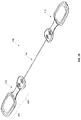
- FIG. 1 is a perspective view of one embodiment of a floss strip.
- FIG. 2 is a top view of one embodiment of the floss strip.
- FIG. 3 is a bottom view of one embodiment of the floss strip.
- FIG. 4 is a front view of one embodiment of the floss strip.
- FIG. 5 is a left side view of one embodiment of the floss strip.
- FIG. 6 is a right side view of one embodiment of the floss strip.
- FIG. 7 is a perspective view of another embodiment of the floss strip.
- FIG. 8 is a top view of another embodiment of the floss strip.
- FIG. 9 is a front view of another embodiment of the floss strip.
- FIG. 10 is a bottom view of another embodiment of the floss strip.
- FIG. 11 is a left side view of another embodiment of the floss strip.
- FIG. 12 is a right side view of another embodiment of the floss strip.
- FIG. 13 is a perspective view of another embodiment of the floss strip.
- FIG. 14 is a top view of another embodiment of the floss strip.
- FIG. 15 is a front view of another embodiment of the floss strip.
- FIG. 16 is a bottom view of another embodiment of the floss strip.
- FIG. 17 is a left side view of another embodiment of the floss strip.
- FIG. 18 is a right side view of another embodiment of the floss strip.
- FIG. 19 is a perspective view of another embodiment of the floss strip.
- FIG. 20 is a top view of another embodiment of the floss strip.
- FIG. 21 is a front view of another embodiment of the floss strip.
- FIG. 22 is a bottom view of another embodiment of the floss strip.
- FIG. 23 is a left side view of another embodiment of the floss strip.
- FIG. 24 is a right side view of another embodiment of the floss strip.
- FIG. 25 is a perspective view of another embodiment of the floss strip.
- FIG. 26 is a front view of another embodiment of the floss strip.
- FIG. 27 is a top view of another embodiment of the floss strip.
- FIG. 28 is a bottom view of another embodiment of the floss strip.
- FIG. 29 is a left side view of another embodiment of the floss strip.
- FIG. 30 is a right side view of another embodiment of the floss strip.
- FIG. 31 is a back view of another embodiment of the floss strip.
- FIG. 32 is a perspective view of another embodiment of the floss strip.
- FIG. 33 is a front view of another embodiment of the floss strip.
- FIG. 34 is a top view of another embodiment of the floss strip.
- FIG. 35 is a bottom view of another embodiment of the floss strip.
- FIG. 36 is a left side view of another embodiment of the floss strip.
- FIG. 37 is a right side view of another embodiment of the floss strip.
- FIG. 38 is a back view of another embodiment of the floss strip.
- FIG. 39 is a perspective view of another embodiment of the floss strip.
- FIG. 40 is a front view of another embodiment of the floss strip.
- FIG. 41 is a top view of another embodiment of the floss strip.
- FIG. 42 is a bottom view of another embodiment of the floss strip.
- FIG. 43 is a left side view of another embodiment of the floss strip.
- FIG. 44 is a right side view of another embodiment of the floss strip.
- FIG. 45 is a back view of another embodiment of the floss strip.
- the present disclosure relates to a floss strip that can be used common some embodiments, for oral hygiene.
- the floss strip can be a linear member that includes a first anchor and a second anchor that are connected by a flossing filament, and in some embodiments that are only connected by a flossing filament.
- This flossing filament can comprise any lubricious fiber sufficiently strong and thin to be used for dental hygiene.
- the flossing filament can comprise any dental floss including, for example, a waxed fiber such as a nylon or cotton fiber, a polytetrafluoroethylene (PTFE) fiber, a ultra-high-molecular-weight polyethylene (UHMPE) fiber, or any other fiber.
- the flossing filament can comprise dental floss.
- the floss strip can be sized, and specifically can have a length such that the user can hold the first anchor in one hand and the second anchor in another hand and tension the flossing strip to allow flossing of teeth throughout the user's mouth.
- the floss can be sized, and of sufficient length such that the user can floss teeth throughout the user's mouth, while all or portions of one or both of the first and second anchors are in the user's mouth.
- the floss strip can include features to allow the user to tension the flossing filament. In some embodiments, these features can be configured to allow the users to tension the flossing filament without directly contacting the flossing filament. These features can include, in some embodiments, flexible portions of anchors and/or one or several tensioning members. In some embodiments, for example, one or both of the first and second anchors can include a rigid portion and a flexible portion, the flexing of which flexible portion can tension the flossing filament. In some embodiments, the flossing strip can include one or several tensioning members that can be located along the flossing filament between the first anchor and the second anchor. In some particular embodiments, this can include a first tensioning member and the second tensioning member.
- the tensioning members can be fixed to the flossing filament such that the position of the tensioning members along the flossing filament is static. In some embodiments, the tensioning members can slide along the flossing filament to thereby change the position of one or more of the tensioning members with respect to the anchors.
- the floss strip improves flossing and flossing outcomes.
- a user contacts the floss directly with the user's fingers by wrapping the flossing around the fingers.
- This direct contact of the finger to the floss can introduce contaminants and bacteria into the user's mouth, and particularly into the periodontal pockets and tissue surrounding the teeth.
- the wrapping of floss around a user's fingers can be uncomfortable and/or painful and can hamper blood flow to the user's fingertips.
- Floss strips, as disclosed herein resolve these shortcomings of traditional floss with a design that allows tensioning of the floss without direct contact of the user to the floss and that improve user comfort in flossing.
- the floss strip can include one or several additional features that can be, in some embodiments, incorporated in one or both of the anchors and/or in the tensioning strip.
- floss strip can include one or more of: a toothpick, a tongue scraper, a gum stimulator, a soft pick, and interdental brush, or the like.
- these additional features can be exposed, and in some embodiments, these additional features can be protected.
- these additional features can be accessed via, for example, a bending of a portion of the floss strip such as, for example, the bending of the anchor in which one or more of these additional features are located.
- FIG. 1 is a perspective view of one embodiment of a floss strip 100 .
- the floss strip 100 can comprise a variety of shapes and sizes and can be made from a variety materials. In some embodiments, the floss strip 100 can comprise length between one and 9 cm, between 2 and 7 cm, between 3 and 6 cm, between 4 and 5 cm, or the like.
- the floss strip 100 includes a flossing filament 102 that has a first end 104 and a second end 106 .
- the floss strip 100 further includes a first anchor 108 coupled to the first end 104 of the flossing filament 102 , and the second anchor 110 coupled to the second end 106 of the flossing filament 102 .
- the flossing filament 102 can, in some embodiments, couple the first anchor 108 and/or the second anchor 110 .
- the first end 104 of the flossing filament 102 can extend into and/or through the first anchor 108
- the second end 106 of the flossing filament 102 can extend into and/or through the second anchor 110 .
- each of the first anchor 108 , and the second anchor 110 can comprise a tab 112 .
- a “tab” refers to a portion of one of the anchors 108 , 110 used for holding or manipulating the anchor 108 , 110 .
- the tab 112 can comprise: a base 114 , a terminus 116 , a first edge 118 extending from the base 114 to the terminus 116 , a second edge 120 extending from the base 114 to the terminus 116 , a top 122 , and the bottom 124 .
- each of the top and the bottom can connect each of the base 114 , the terminus 116 , the first edge 118 , and the second edge 120 .
- the floss strip 100 can include one or several tensioning members 130 that can be attached to the flossing filament 102 , and an intermediate location between the first anchor 108 and the second anchor 110 .
- the floss strip 100 includes a first tensioning member 130 -A and the second tensioning member 130 -B, which tensioning member is located between the first tensioning member 130 -A and the second anchor 110
- the tensioning members 130 can divide the flossing filament 102 into flossing segments 132 , and specifically as shown FIG. 1 , the first tensioning member 130 -A second tensioning member 130 -B can divide the flossing filament 102 into a first flossing segment 132 -A, a second flossing segment 132 -B, and a third flossing segment 132 -C.
- each of the segments 132 can comprise the same length, and in some embodiments, some or all of the segments 132 can comprise different lengths.
- the first flossing segment 132 -A in the third flossing segment 132 -C can have the same length
- the second flossing segment 132 -B can have a different length.
- the tensioning members 130 can comprise a variety of shapes and sizes, and the tensioning elements 130 and the anchors 108 , 110 can be made from a variety materials.
- the tensioning elements 130 and the anchors 108 , 110 can comprise one or several polymers, ceramics, natural materials, metals, composite materials, and the like.
- each of the tensioning elements 130 , and the anchors 108 , 110 can comprise a molded polymer such as, for example, an injection molded polymer.
- the tensioning members 130 can be flexible. In some embodiments, this flexibility can allow tensioning of the flossing filament 102 , and/or of one or several flossing segments 132 of the flossing filament. In some embodiments, some or all of the tensioning elements 130 can comprise one or several flexing features 134 , that can be configured to allow flexing of the tensioning member 130 . In the embodiment depicted in FIG. 1 , the flexing features 134 can comprise at least one, and more specifically a plurality of hills 136 , and valleys 138 . In some embodiments, these hills 136 , and valleys 138 , can facilitate flexing of the tensioning member 130 .
- one or several of the tensioning members 130 can have a position fixed with respect to the flossing filament 102 , and/or to the anchors 108 , 110 . In some embodiments, one or several the tensioning members 130 can be slidable along the flossing filament between, for example, the first anchor 108 in the second anchor 110 . In some such embodiments, the sliding ability of one or more of the tensioning members 134 , can facilitate sterile use of the floss strip 100 by preventing direct contact of the fingers of the user or of another to the flossing filament 102 . Further the inclusion of the tensioning members 130 can eliminate the need to directly contact the floss to tension the floss and/or to wrap floss around the user's fingers to tension the floss.
- the floss strip 100 can have a configuration similar to that of FIG. 1 , but the floss strip 100 can include a single anchor 108 , a single tensioning member 130 , and the floss flossing filament 102 can extend beyond the single anchor 108 .
- the portion of the flossing filament 102 extending beyond the single anchor 108 , which portion of the flossing filament 102 comprises the second flossing segment 132 -B can have any desired length, including, for example, a length of up to 40 centimeters, a length of up to 30 centimeters, a length of up to 20 centimeters, a length between 2 and 20 centimeters, a length between 4 and 16 centimeters, a length between 10 and 15 centimeters, or a length of any other intermediate value or range.
- the floss strip 100 includes a flossing filament 102 , a first end 108 , second anchor 110 , and tensioning members 130 .
- FIG. 3 a bottom view of one embodiment of the floss strip 100 is shown, and with reference now to FIG. 4 , a front view of one embodiment of the floss strip 100 is shown.
- FIG. 5 a left side view of the floss strip 100 is shown, and specifically of the first anchor 108 is shown.
- the first end 104 of the flossing filament 102 is visible in the terminus 116 of the first anchor 108 .
- FIG. 6 a right side view of the floss strip 100 is shown, and specifically of the second anchor 110 is shown.
- the second end 106 of the flossing filament 102 is visible in the terminus 116 of the second anchor 110 .
- FIG. 7 depicts a perspective view of the floss strip 100 including a flossing filament 102 , a first anchor 108 , a second anchor 110 , and tensioning members 130 .
- FIG. 8 is a top view of the floss strip 100
- FIG. 9 is a front view of the floss strip 100
- FIG. 10 is a bottom view of the floss strip 100 .
- FIG. 11 is a left side view of the floss strip 100
- FIG. 12 is a front side view of the floss strip 100 .
- the first anchor 108 is connected to the second anchor 110 via the flossing element 102
- the first anchor 108 is connected to the second anchor 110 only via the flossing filament 102 .
- FIGS. 13 through 18 depict another embodiment of the floss strip 100 .
- the floss strip 100 includes a flossing filament 102 , a first anchor 108 , and a second anchor 110 .
- Each of the first anchor 108 , and the second anchor 110 can comprise a tab 112 .
- the tab 112 can comprise: a base 114 , a terminus 116 , a first edge 118 extending from the base 114 to the terminus 116 , a second end 120 extending from the base 114 to the terminus 116 , a top 122 , and the bottom 124 .
- each of the top and the bottom can connect each of the base 114 , the terminus 116 , the first edge 118 , and the second edge 120 .
- first and second anchors 108 , 110 can comprise a gripping portion 200 and a tensioning portion 202 .
- the gripping portion 200 can be relatively more proximate to the terminus 116 of the anchor 108 , 110
- the tensioning portion 202 can be relatively more proximate to the base 114 of the anchor 108 , 110 .
- the tensioning portion 202 can be flexible to allow the tensioning of the flossing filament 102 via the flexing of the tensioning portion 202 of one of the anchors 108 , 110 .
- the tensioning portion 202 can include one or several flexing features 204 that can enable the flexing of the tensioning portion 202 .
- the flexing features 204 can comprise one or several ribs, peaks 206 and/or valleys 208 , or the like.
- the peaks 206 and valleys 208 of the tensioning portion 202 of the anchor 108 , 110 enable flexing of the tensioning member 202 .
- one or both of the anchors 108 , 110 can comprise a pick 210 , such as an exposed pick or a protected pick (shown in FIG. 13 ), having a point 212 and a pick-base 214 .
- the pick 210 can comprise an integral pick. The pick can extend along at least a portion of the first edge 118 from the base 114 to the terminus 116 and/or from a position relatively more proximate to the base 114 to a position relatively less proximate to the base 114 .
- the pick 210 extends from a portion of the anchor 108 , 110 to the point 212 , and specifically, in some embodiments, the pick 210 extends from a flex-channel 216 of the anchor to the point 212 of the pick 210 . In the embodiment depicted in FIG. 13 , the pick 210 extends from the pick-base 214 which is relatively more proximate to the base 114 of the anchor 108 , 110 to a position relatively less distal to the base 114 of the anchor 108 , 110 .
- the anchor 108 , 110 can comprise one or several features configured to allow deployment of the pick 210 . In some embodiments, these features can include one or several features of the anchor 108 , 110 configured to enhance flexibility of the anchor 108 , 110 .
- the anchor 108 , 110 containing the pick 210 can comprise a flex-channel 216 located proximate to the pick-base 214 of the pick 210 .
- the flex-channel 216 can, in some embodiments, allow bending of the anchor 108 , 110 containing the pick 210 to deploy the pick 210 , and specifically to deploy the point 212 of the pick 210 .
- the flex-channel 216 can extend at least partially from the second edge 120 to and/or towards the first edge 118 , and the flex-channel can be configured to allow flexing of the anchor 108 , 110 to expose the point 212 of the pick 210 .
- the floss strip 100 can have a length 219 that can be divided into a length 220 of the first anchor 108 , a length 224 of the second anchor 110 , and a length 222 of an exposed portion 218 of the flossing filament 102 .
- floss strip 100 can comprise length between one and 9 cm, between 2 and 7 cm, between 3 and 6 cm, between 4 and 5 cm, or the like.
- the floss strip 100 has a length such that the exposed portion 218 of the flossing filament 102 can be tensioned in the mouth of a user when all or portions of the first anchor 108 in the second anchor 110 are also in the user's mouth.
- length 220 of the first anchor 108 and the length 224 of the second anchor 110 can be the same, and can be between, for example, 1 and 6 centimeters, between 1.5 and 4 centimeters, between 2 and three centimeters, and/or in any other or intermediate range.
- the length 222 of the exposed portion 218 of the flossing filament 102 can be, for example, between 1 and 8 centimeters, between 2 and 6 centimeters, between 2 and 4 centimeters, and/or in any other or intermediate range.
- the floss strip 100 can have a total length, in some embodiments, between approximately 4 and 25 centimeters, between 6 and 20 centimeters, between 8 and 18 centimeters, and/or between 10 and 15 centimeters.
- a floss strip 100 having a length between 10 and 15 centimeters enables tensioning of the flossing filament 102 in the user's mouth when all or portions of the first and second anchors 108 , 110 are also in the user's mouth. This ability can advantageously facilitate improved flossing and can facilitate and maintain the sterility of the flossing filament 102 .
- FIG. 19 depicts a perspective view of the floss strip 100 including a flossing filament 102 , a first anchor 108 , a second anchor 110 and an integral pick 210 .
- FIG. 20 is a top view of the floss strip 100
- FIG. 21 is a front view of the floss strip 100
- FIG. 22 is a bottom view of the floss strip 100 .
- FIG. 24 is a left side view of the floss strip 100
- FIG. 23 is a right side view of the floss strip 100 .
- the first anchor 108 is connected to the second anchor 110 via the flossing element 102
- the first anchor 108 is connected to the second anchor 110 only via the flossing filament 102 .
- FIGS. 25 through 38 show embodiments of the floss strip 100 in which the tensioning element 134 comprises a series of beads 300 , which beads can have any desired shape including, for example, round, rectangular, square, triangular, polygonal, or the like.
- the beads 300 can comprise one or several spheres. In some embodiments, some or all of the beads 300 and/or spheres can be independently coupled to the flossing filament 102 .
- Some embodiments relate to method of using the floss strip 100 for performing oral hygiene.
- the method can include, inserting the floss strip 100 into a human mouth.
- the floss strip 100 can include, as discussed above, a flossing filament 102 having a first end 104 , and a second end 106 ; a first anchor 108 coupled to the flossing filament 102 at the first end 104 of the flossing filament 102 ; and a second anchor 110 coupled to the flossing filament 102 at the second end 106 of the flossing filament 102 , the flossing filament 102 coupling the first and second anchors 108 , 110 .
- the method can include flossing between teeth in the mouth with the flossing filament 102 .
- the method can further include deploying a protected pick 210 from the first anchor 108 .
- deploying the protected pick 210 from the first anchor 108 comprises bending the first anchor 108 to expose a point 212 of the protected pick 210 .
- the method can include, inserting the floss strip 100 into a human mouth.
- the floss strip 100 can include, as discussed above, a flossing filament 102 having a first end 104 , and a second end 106 ; a first anchor 108 coupled to the flossing filament 102 at the first end 104 of the flossing filament 102 ; a second anchor 110 coupled to the flossing filament 102 at the second end 106 of the flossing filament 102 , the flossing filament 102 coupling the first and second anchors 108 , 110 , and a tensioning member attached to the flossing filament at an intermediate location between the first anchor and the second anchor.
- the method can include flossing between teeth in the mouth with the flossing filament 102 .
- controlling the tensioning member 130 can include flexing the tensioning member 130 .
- the method further includes displacing the tensioning member 130 along the flossing filament 102 to change a distance between the tensioning member 130 and the first anchor 108 .
Landscapes
- Health & Medical Sciences (AREA)
- Dentistry (AREA)
- Epidemiology (AREA)
- Life Sciences & Earth Sciences (AREA)
- Animal Behavior & Ethology (AREA)
- General Health & Medical Sciences (AREA)
- Public Health (AREA)
- Veterinary Medicine (AREA)
- Brushes (AREA)
Abstract
Description
Claims (33)
Priority Applications (2)
| Application Number | Priority Date | Filing Date | Title |
|---|---|---|---|
| US16/501,124 US11559381B2 (en) | 2018-11-15 | 2018-11-15 | Gripping element floss |
| US18/156,147 US12186146B2 (en) | 2018-11-15 | 2023-01-18 | Gripping element floss |
Applications Claiming Priority (1)
| Application Number | Priority Date | Filing Date | Title |
|---|---|---|---|
| US16/501,124 US11559381B2 (en) | 2018-11-15 | 2018-11-15 | Gripping element floss |
Related Child Applications (1)
| Application Number | Title | Priority Date | Filing Date |
|---|---|---|---|
| US18/156,147 Continuation US12186146B2 (en) | 2018-11-15 | 2023-01-18 | Gripping element floss |
Publications (2)
| Publication Number | Publication Date |
|---|---|
| US20200237488A1 US20200237488A1 (en) | 2020-07-30 |
| US11559381B2 true US11559381B2 (en) | 2023-01-24 |
Family
ID=71733158
Family Applications (2)
| Application Number | Title | Priority Date | Filing Date |
|---|---|---|---|
| US16/501,124 Active 2039-04-23 US11559381B2 (en) | 2018-11-15 | 2018-11-15 | Gripping element floss |
| US18/156,147 Active US12186146B2 (en) | 2018-11-15 | 2023-01-18 | Gripping element floss |
Family Applications After (1)
| Application Number | Title | Priority Date | Filing Date |
|---|---|---|---|
| US18/156,147 Active US12186146B2 (en) | 2018-11-15 | 2023-01-18 | Gripping element floss |
Country Status (1)
| Country | Link |
|---|---|
| US (2) | US11559381B2 (en) |
Families Citing this family (2)
| Publication number | Priority date | Publication date | Assignee | Title |
|---|---|---|---|---|
| USD965225S1 (en) * | 2021-10-26 | 2022-09-27 | Kaveh Niknia | Flossing apparatus |
| USD1013958S1 (en) | 2022-08-19 | 2024-02-06 | Kaveh Niknia | Dental floss |
Citations (33)
| Publication number | Priority date | Publication date | Assignee | Title |
|---|---|---|---|---|
| US2180522A (en) * | 1938-11-01 | 1939-11-21 | Henne Isabelle | Dental floss throw-away unit and method of making same |
| US4016892A (en) * | 1974-06-24 | 1977-04-12 | Placontrol, Inc. | Dental floss holder |
| US4162687A (en) * | 1978-06-06 | 1979-07-31 | Lorch Leonard G | Dental flossing device |
| US4403625A (en) * | 1981-10-23 | 1983-09-13 | Sanders James B | Disposable buccal hygenic device |
| US4638824A (en) * | 1985-09-09 | 1987-01-27 | Hoz Jorge W De | Dental floss device |
| US5086792A (en) * | 1989-02-16 | 1992-02-11 | Placontrol Corp. | Dental floss loop devices, and methods of manufacture and packaging same |
| US5435330A (en) * | 1994-04-05 | 1995-07-25 | Dix; Sean | Dental floss device |
| USD406395S (en) * | 1998-04-09 | 1999-03-02 | Marin Rodolfo R | Dental floss holder with toothpick |
| US5911229A (en) * | 1997-06-20 | 1999-06-15 | Placontrol, Inc. | Dental flossing device |
| US5931171A (en) * | 1998-07-14 | 1999-08-03 | Op-D-Op, Inc. | Dental flossing apparatus |
| US6112753A (en) * | 1999-07-17 | 2000-09-05 | Arsenault; Peter | Dental floss |
| US6397853B1 (en) * | 1998-09-10 | 2002-06-04 | James S. Lovick | Filament cleaning tool for fingernails |
| US20040168703A1 (en) * | 2001-04-09 | 2004-09-02 | Cho Myoung-Ho | Floss-pick |
| US20050279377A1 (en) * | 2004-06-16 | 2005-12-22 | Sarjeant Peter T | Dental flossing agents, methods of use and manufacture |
| US20050288709A1 (en) * | 2003-06-11 | 2005-12-29 | Fallin T W | Adjustable line locks and methods |
| WO2008098292A1 (en) * | 2007-02-14 | 2008-08-21 | Flosspik Pty Ltd | Oral hygiene device |
| US20100107419A1 (en) * | 2008-06-25 | 2010-05-06 | Crisp Jackson L | Eating utensil incorporating oral cleaning facility |
| USD637762S1 (en) * | 2009-12-09 | 2011-05-10 | Dr. Fresh, Inc. | Flosser with pick |
| US20120103356A1 (en) * | 2008-06-25 | 2012-05-03 | Crisp Jackson L | Eating utensil incorporating oral hygienic facility |
| US20120111348A1 (en) * | 2010-11-04 | 2012-05-10 | Walter Prokopchuk | Floss pick |
| US8297290B2 (en) * | 2009-09-29 | 2012-10-30 | Welter's Co., Ltd. | Multi-angled dental floss holder |
| US20130025623A1 (en) * | 2011-07-28 | 2013-01-31 | Karl Herzog | Handling aid for dental floss |
| USD681879S1 (en) * | 2011-10-24 | 2013-05-07 | Ranir, Llc | Portion of a floss device |
| US8776807B2 (en) * | 2011-10-04 | 2014-07-15 | Michael Zinovy Royzen | Dental device |
| US20140326274A1 (en) * | 2013-05-02 | 2014-11-06 | Ranir, Llc | Dental flossers |
| US20150265383A1 (en) * | 2014-03-18 | 2015-09-24 | Flexi Floss Ltd. | Dental flossing device |
| US9277977B2 (en) | 2011-01-24 | 2016-03-08 | Leonard G. Lorch | Dental floss |
| US20160067021A1 (en) * | 2013-04-16 | 2016-03-10 | Trisa Holding Ag | Flosser |
| USD777377S1 (en) * | 2016-01-06 | 2017-01-24 | Jason Dudley | Combination dental floss and pick |
| US9717575B2 (en) * | 2014-08-11 | 2017-08-01 | Sacks Holdings, Inc. | Hybrid dental tool with detachable picks |
| US10517703B2 (en) * | 2014-03-18 | 2019-12-31 | Flexi Floss Ltd. | Dental flossing device |
| US10856958B2 (en) * | 2014-03-06 | 2020-12-08 | Tepe Munhygienprodukter Ab | Interdental cleaner |
| US20200383694A1 (en) * | 2019-06-06 | 2020-12-10 | Open Arms Holdings LLC | Forward Pulling Sculpted Edge Tongue Scraper with Dental Flosser and Dental Pick |
Family Cites Families (2)
| Publication number | Priority date | Publication date | Assignee | Title |
|---|---|---|---|---|
| US5174314A (en) * | 1991-06-17 | 1992-12-29 | Norman Charatan | Oral hygiene device |
| US7281541B2 (en) * | 2004-06-16 | 2007-10-16 | Lorch Leonard G | Dental floss |
-
2018
- 2018-11-15 US US16/501,124 patent/US11559381B2/en active Active
-
2023
- 2023-01-18 US US18/156,147 patent/US12186146B2/en active Active
Patent Citations (34)
| Publication number | Priority date | Publication date | Assignee | Title |
|---|---|---|---|---|
| US2180522A (en) * | 1938-11-01 | 1939-11-21 | Henne Isabelle | Dental floss throw-away unit and method of making same |
| US4016892A (en) * | 1974-06-24 | 1977-04-12 | Placontrol, Inc. | Dental floss holder |
| US4162687A (en) * | 1978-06-06 | 1979-07-31 | Lorch Leonard G | Dental flossing device |
| US4403625A (en) * | 1981-10-23 | 1983-09-13 | Sanders James B | Disposable buccal hygenic device |
| US4638824A (en) * | 1985-09-09 | 1987-01-27 | Hoz Jorge W De | Dental floss device |
| US5086792A (en) * | 1989-02-16 | 1992-02-11 | Placontrol Corp. | Dental floss loop devices, and methods of manufacture and packaging same |
| US5435330A (en) * | 1994-04-05 | 1995-07-25 | Dix; Sean | Dental floss device |
| US5911229A (en) * | 1997-06-20 | 1999-06-15 | Placontrol, Inc. | Dental flossing device |
| USD406395S (en) * | 1998-04-09 | 1999-03-02 | Marin Rodolfo R | Dental floss holder with toothpick |
| US5931171A (en) * | 1998-07-14 | 1999-08-03 | Op-D-Op, Inc. | Dental flossing apparatus |
| US6397853B1 (en) * | 1998-09-10 | 2002-06-04 | James S. Lovick | Filament cleaning tool for fingernails |
| US6112753A (en) * | 1999-07-17 | 2000-09-05 | Arsenault; Peter | Dental floss |
| US20040168703A1 (en) * | 2001-04-09 | 2004-09-02 | Cho Myoung-Ho | Floss-pick |
| US20050288709A1 (en) * | 2003-06-11 | 2005-12-29 | Fallin T W | Adjustable line locks and methods |
| US20050279377A1 (en) * | 2004-06-16 | 2005-12-22 | Sarjeant Peter T | Dental flossing agents, methods of use and manufacture |
| US20100018547A1 (en) * | 2007-02-14 | 2010-01-28 | Flosspik Ptv Ltd | Oral hygiene device |
| WO2008098292A1 (en) * | 2007-02-14 | 2008-08-21 | Flosspik Pty Ltd | Oral hygiene device |
| US20100107419A1 (en) * | 2008-06-25 | 2010-05-06 | Crisp Jackson L | Eating utensil incorporating oral cleaning facility |
| US20120103356A1 (en) * | 2008-06-25 | 2012-05-03 | Crisp Jackson L | Eating utensil incorporating oral hygienic facility |
| US8297290B2 (en) * | 2009-09-29 | 2012-10-30 | Welter's Co., Ltd. | Multi-angled dental floss holder |
| USD637762S1 (en) * | 2009-12-09 | 2011-05-10 | Dr. Fresh, Inc. | Flosser with pick |
| US20120111348A1 (en) * | 2010-11-04 | 2012-05-10 | Walter Prokopchuk | Floss pick |
| US9277977B2 (en) | 2011-01-24 | 2016-03-08 | Leonard G. Lorch | Dental floss |
| US20130025623A1 (en) * | 2011-07-28 | 2013-01-31 | Karl Herzog | Handling aid for dental floss |
| US8776807B2 (en) * | 2011-10-04 | 2014-07-15 | Michael Zinovy Royzen | Dental device |
| USD681879S1 (en) * | 2011-10-24 | 2013-05-07 | Ranir, Llc | Portion of a floss device |
| US20160067021A1 (en) * | 2013-04-16 | 2016-03-10 | Trisa Holding Ag | Flosser |
| US20140326274A1 (en) * | 2013-05-02 | 2014-11-06 | Ranir, Llc | Dental flossers |
| US10856958B2 (en) * | 2014-03-06 | 2020-12-08 | Tepe Munhygienprodukter Ab | Interdental cleaner |
| US20150265383A1 (en) * | 2014-03-18 | 2015-09-24 | Flexi Floss Ltd. | Dental flossing device |
| US10517703B2 (en) * | 2014-03-18 | 2019-12-31 | Flexi Floss Ltd. | Dental flossing device |
| US9717575B2 (en) * | 2014-08-11 | 2017-08-01 | Sacks Holdings, Inc. | Hybrid dental tool with detachable picks |
| USD777377S1 (en) * | 2016-01-06 | 2017-01-24 | Jason Dudley | Combination dental floss and pick |
| US20200383694A1 (en) * | 2019-06-06 | 2020-12-10 | Open Arms Holdings LLC | Forward Pulling Sculpted Edge Tongue Scraper with Dental Flosser and Dental Pick |
Also Published As
| Publication number | Publication date |
|---|---|
| US20200237488A1 (en) | 2020-07-30 |
| US20230363869A1 (en) | 2023-11-16 |
| US12186146B2 (en) | 2025-01-07 |
Similar Documents
| Publication | Publication Date | Title |
|---|---|---|
| US20230293277A1 (en) | Hybrid Dental Device | |
| US12186146B2 (en) | Gripping element floss | |
| US5738513A (en) | Archwire locking device for orthodontic bracket | |
| US4913654A (en) | Shield for orthodontic appliance | |
| US9610009B2 (en) | Dental retractor for protecting a patient's teeth from contact with the inner side of a patient's mouth and tongue | |
| JP2011505170A (en) | Dental retainer | |
| US20250318902A1 (en) | Lip And Cheek Expander | |
| US20180353274A1 (en) | Adjustable interdental cleaning element and a device and method therefor | |
| US11051604B2 (en) | Infant toothbrush | |
| US7713057B2 (en) | Oral mucous membrane protector for orthodontic applications | |
| US9936798B2 (en) | Tooth brush and flossing aid combination | |
| US11123166B2 (en) | Dual head dental floss pick | |
| EP3082637B1 (en) | Dental oral shield system | |
| KR20120115044A (en) | Hole braket for orthodontics | |
| CN222398885U (en) | Adjustable bending dental floss rod | |
| US20100248185A1 (en) | Dental pin and use thereof | |
| KR20090128048A (en) | Dental Oral Retractor | |
| JP3223034U (en) | Oral mucosa protector for bracket | |
| Mackenzie et al. | Splendid isolation: a practical guide to the use of rubber dam part 2 | |
| CN210044152U (en) | Gum forceps | |
| CN223627619U (en) | Dental instruments | |
| KR101366038B1 (en) | Self ligating bracket | |
| US20240324871A1 (en) | Endodontic surgery tissue retractor device | |
| US20090148812A1 (en) | Device for Dispensing Active or Passive Substance Embedded in the Oral Cavity | |
| KR20120007238U (en) | . Hole braket for orthodontics |
Legal Events
| Date | Code | Title | Description |
|---|---|---|---|
| FEPP | Fee payment procedure |
Free format text: ENTITY STATUS SET TO UNDISCOUNTED (ORIGINAL EVENT CODE: BIG.); ENTITY STATUS OF PATENT OWNER: SMALL ENTITY |
|
| FEPP | Fee payment procedure |
Free format text: ENTITY STATUS SET TO SMALL (ORIGINAL EVENT CODE: SMAL); ENTITY STATUS OF PATENT OWNER: SMALL ENTITY |
|
| AS | Assignment |
Owner name: SACKS HOLDINGS, INC., CALIFORNIA Free format text: ASSIGNMENT OF ASSIGNORS INTEREST;ASSIGNOR:CHODOROW, DEVIN S.;REEL/FRAME:052653/0448 Effective date: 20200512 |
|
| STPP | Information on status: patent application and granting procedure in general |
Free format text: NON FINAL ACTION MAILED |
|
| STPP | Information on status: patent application and granting procedure in general |
Free format text: NON FINAL ACTION MAILED Free format text: RESPONSE TO NON-FINAL OFFICE ACTION ENTERED AND FORWARDED TO EXAMINER |
|
| STPP | Information on status: patent application and granting procedure in general |
Free format text: RESPONSE TO NON-FINAL OFFICE ACTION ENTERED AND FORWARDED TO EXAMINER |
|
| STPP | Information on status: patent application and granting procedure in general |
Free format text: FINAL REJECTION MAILED |
|
| STPP | Information on status: patent application and granting procedure in general |
Free format text: ADVISORY ACTION MAILED |
|
| STPP | Information on status: patent application and granting procedure in general |
Free format text: DOCKETED NEW CASE - READY FOR EXAMINATION |
|
| STPP | Information on status: patent application and granting procedure in general |
Free format text: NON FINAL ACTION MAILED |
|
| STPP | Information on status: patent application and granting procedure in general |
Free format text: RESPONSE TO NON-FINAL OFFICE ACTION ENTERED AND FORWARDED TO EXAMINER |
|
| STPP | Information on status: patent application and granting procedure in general |
Free format text: NOTICE OF ALLOWANCE MAILED -- APPLICATION RECEIVED IN OFFICE OF PUBLICATIONS |
|
| STPP | Information on status: patent application and granting procedure in general |
Free format text: PUBLICATIONS -- ISSUE FEE PAYMENT VERIFIED |
|
| STCF | Information on status: patent grant |
Free format text: PATENTED CASE |