US11557947B2 - Stators and rotors with varying insulative density - Google Patents
Stators and rotors with varying insulative density Download PDFInfo
- Publication number
- US11557947B2 US11557947B2 US16/598,698 US201916598698A US11557947B2 US 11557947 B2 US11557947 B2 US 11557947B2 US 201916598698 A US201916598698 A US 201916598698A US 11557947 B2 US11557947 B2 US 11557947B2
- Authority
- US
- United States
- Prior art keywords
- discrete
- electric machine
- outer periphery
- cells
- stator
- Prior art date
- Legal status (The legal status is an assumption and is not a legal conclusion. Google has not performed a legal analysis and makes no representation as to the accuracy of the status listed.)
- Active, expires
Links
Images


Classifications
-
- H—ELECTRICITY
- H02—GENERATION; CONVERSION OR DISTRIBUTION OF ELECTRIC POWER
- H02K—DYNAMO-ELECTRIC MACHINES
- H02K1/00—Details of the magnetic circuit
- H02K1/04—Details of the magnetic circuit characterised by the material used for insulating the magnetic circuit or parts thereof
-
- H—ELECTRICITY
- H02—GENERATION; CONVERSION OR DISTRIBUTION OF ELECTRIC POWER
- H02K—DYNAMO-ELECTRIC MACHINES
- H02K15/00—Processes or apparatus specially adapted for manufacturing, assembling, maintaining or repairing of dynamo-electric machines
- H02K15/12—Impregnating, moulding insulation, heating or drying of windings, stators, rotors or machines
-
- H—ELECTRICITY
- H02—GENERATION; CONVERSION OR DISTRIBUTION OF ELECTRIC POWER
- H02K—DYNAMO-ELECTRIC MACHINES
- H02K1/00—Details of the magnetic circuit
- H02K1/06—Details of the magnetic circuit characterised by the shape, form or construction
- H02K1/12—Stationary parts of the magnetic circuit
- H02K1/14—Stator cores with salient poles
- H02K1/146—Stator cores with salient poles consisting of a generally annular yoke with salient poles
-
- B—PERFORMING OPERATIONS; TRANSPORTING
- B22—CASTING; POWDER METALLURGY
- B22F—WORKING METALLIC POWDER; MANUFACTURE OF ARTICLES FROM METALLIC POWDER; MAKING METALLIC POWDER; APPARATUS OR DEVICES SPECIALLY ADAPTED FOR METALLIC POWDER
- B22F5/00—Manufacture of workpieces or articles from metallic powder characterised by the special shape of the product
- B22F5/009—Manufacture of workpieces or articles from metallic powder characterised by the special shape of the product of turbine components other than turbine blades
-
- H—ELECTRICITY
- H02—GENERATION; CONVERSION OR DISTRIBUTION OF ELECTRIC POWER
- H02K—DYNAMO-ELECTRIC MACHINES
- H02K1/00—Details of the magnetic circuit
- H02K1/06—Details of the magnetic circuit characterised by the shape, form or construction
- H02K1/12—Stationary parts of the magnetic circuit
-
- H—ELECTRICITY
- H02—GENERATION; CONVERSION OR DISTRIBUTION OF ELECTRIC POWER
- H02K—DYNAMO-ELECTRIC MACHINES
- H02K1/00—Details of the magnetic circuit
- H02K1/06—Details of the magnetic circuit characterised by the shape, form or construction
- H02K1/12—Stationary parts of the magnetic circuit
- H02K1/18—Means for mounting or fastening magnetic stationary parts on to, or to, the stator structures
- H02K1/185—Means for mounting or fastening magnetic stationary parts on to, or to, the stator structures to outer stators
-
- H—ELECTRICITY
- H02—GENERATION; CONVERSION OR DISTRIBUTION OF ELECTRIC POWER
- H02K—DYNAMO-ELECTRIC MACHINES
- H02K1/00—Details of the magnetic circuit
- H02K1/06—Details of the magnetic circuit characterised by the shape, form or construction
- H02K1/22—Rotating parts of the magnetic circuit
- H02K1/24—Rotor cores with salient poles ; Variable reluctance rotors
- H02K1/246—Variable reluctance rotors
-
- H—ELECTRICITY
- H02—GENERATION; CONVERSION OR DISTRIBUTION OF ELECTRIC POWER
- H02K—DYNAMO-ELECTRIC MACHINES
- H02K15/00—Processes or apparatus specially adapted for manufacturing, assembling, maintaining or repairing of dynamo-electric machines
- H02K15/02—Processes or apparatus specially adapted for manufacturing, assembling, maintaining or repairing of dynamo-electric machines of stator or rotor bodies
- H02K15/021—Magnetic cores
-
- H02K15/024—
-
- H—ELECTRICITY
- H02—GENERATION; CONVERSION OR DISTRIBUTION OF ELECTRIC POWER
- H02K—DYNAMO-ELECTRIC MACHINES
- H02K3/00—Details of windings
- H02K3/04—Windings characterised by the conductor shape, form or construction, e.g. with bar conductors
- H02K3/26—Windings characterised by the conductor shape, form or construction, e.g. with bar conductors consisting of printed conductors
-
- H—ELECTRICITY
- H02—GENERATION; CONVERSION OR DISTRIBUTION OF ELECTRIC POWER
- H02K—DYNAMO-ELECTRIC MACHINES
- H02K3/00—Details of windings
- H02K3/04—Windings characterised by the conductor shape, form or construction, e.g. with bar conductors
- H02K3/28—Layout of windings or of connections between windings
-
- H—ELECTRICITY
- H02—GENERATION; CONVERSION OR DISTRIBUTION OF ELECTRIC POWER
- H02K—DYNAMO-ELECTRIC MACHINES
- H02K3/00—Details of windings
- H02K3/32—Windings characterised by the shape, form or construction of the insulation
- H02K3/34—Windings characterised by the shape, form or construction of the insulation between conductors or between conductor and core, e.g. slot insulation
-
- B—PERFORMING OPERATIONS; TRANSPORTING
- B22—CASTING; POWDER METALLURGY
- B22F—WORKING METALLIC POWDER; MANUFACTURE OF ARTICLES FROM METALLIC POWDER; MAKING METALLIC POWDER; APPARATUS OR DEVICES SPECIALLY ADAPTED FOR METALLIC POWDER
- B22F2999/00—Aspects linked to processes or compositions used in powder metallurgy
-
- B—PERFORMING OPERATIONS; TRANSPORTING
- B33—ADDITIVE MANUFACTURING TECHNOLOGY
- B33Y—ADDITIVE MANUFACTURING, i.e. MANUFACTURING OF THREE-DIMENSIONAL [3D] OBJECTS BY ADDITIVE DEPOSITION, ADDITIVE AGGLOMERATION OR ADDITIVE LAYERING, e.g. BY 3D PRINTING, STEREOLITHOGRAPHY OR SELECTIVE LASER SINTERING
- B33Y10/00—Processes of additive manufacturing
-
- B—PERFORMING OPERATIONS; TRANSPORTING
- B33—ADDITIVE MANUFACTURING TECHNOLOGY
- B33Y—ADDITIVE MANUFACTURING, i.e. MANUFACTURING OF THREE-DIMENSIONAL [3D] OBJECTS BY ADDITIVE DEPOSITION, ADDITIVE AGGLOMERATION OR ADDITIVE LAYERING, e.g. BY 3D PRINTING, STEREOLITHOGRAPHY OR SELECTIVE LASER SINTERING
- B33Y80/00—Products made by additive manufacturing
-
- C—CHEMISTRY; METALLURGY
- C22—METALLURGY; FERROUS OR NON-FERROUS ALLOYS; TREATMENT OF ALLOYS OR NON-FERROUS METALS
- C22C—ALLOYS
- C22C2202/00—Physical properties
- C22C2202/02—Magnetic
-
- Y—GENERAL TAGGING OF NEW TECHNOLOGICAL DEVELOPMENTS; GENERAL TAGGING OF CROSS-SECTIONAL TECHNOLOGIES SPANNING OVER SEVERAL SECTIONS OF THE IPC; TECHNICAL SUBJECTS COVERED BY FORMER USPC CROSS-REFERENCE ART COLLECTIONS [XRACs] AND DIGESTS
- Y02—TECHNOLOGIES OR APPLICATIONS FOR MITIGATION OR ADAPTATION AGAINST CLIMATE CHANGE
- Y02T—CLIMATE CHANGE MITIGATION TECHNOLOGIES RELATED TO TRANSPORTATION
- Y02T10/00—Road transport of goods or passengers
- Y02T10/60—Other road transportation technologies with climate change mitigation effect
- Y02T10/64—Electric machine technologies in electromobility
Definitions
- This disclosure relates to the construction of electric machine components.
- An automotive vehicle may include a battery to power an electric machine that is arranged to propel wheels of the vehicle.
- Control of the battery including charge, discharge, and cell balance operations, may depend on voltages of cells of the battery.
- the electric machine may include a stator and rotor.
- the stator is typically stationary. Energy flows through the stator to or from the rotor.
- the stator provides a rotating magnetic field that drives the rotating armature.
- the stator converts the rotating magnetic field to electric current.
- the rotor is the moving component. Its rotation is due to the interaction between the windings and magnetic fields, which produces a torque around the rotor's axis.
- An electric machine includes a plurality of printed layers arranged to form a stator having an outer periphery and teeth extending radially inward from the outer periphery.
- Each of the printed layers includes discrete portions of metal and discrete portions of insulation.
- the discrete portions of insulation define a contiguous network of insulative boundaries separating discrete cells formed by the discrete portions of the metal.
- a volume of the discrete cells within the outer periphery is greater than a volume of the discrete cells within the teeth such that a reluctance of the teeth is greater than a reluctance of the outer periphery.
- the electric machine also includes a rotor disposed within the stator adjacent to the teeth.
- An electric machine includes a plurality of printed layers arranged to form a rotor having an outer periphery and an inner periphery.
- Each of the printed layers includes discrete portions of metal and discrete portions of insulation.
- the discrete portions of insulation define a contiguous network of insulative boundaries separating discrete cells formed by the discrete portions of the metal.
- a volume of the discrete cells within the outer periphery is less than a volume of the discrete cells within the inner periphery such that a reluctance of the outer periphery is greater than a reluctance of the inner periphery.
- the electric machine also includes a stator having a periphery and teeth, extending radially inward from the periphery, that surround the rotor.
- An electric machine includes a plurality of printed layers arranged to form a stator and a rotor disposed within the stator. Some of the plurality of printed layers includes discrete portions of metal and discrete portions of insulation and other of the plurality of printed layers includes discrete portions of the metal only such that at least one of the stator or rotor defines fins.
- FIG. 1 is plan view of a part of a conventional rotor showing areas of differing core loss.
- FIG. 2 A is a perspective view of a part of a conventional stator.
- FIG. 2 B is an enlarged view of a portion of the stator of FIG. 2 A
- FIG. 3 A is a perspective view of a part of a stator having more insulative material in certain regions as compared with others.
- FIG. 3 B is an enlarged view of a portion of the stator of FIG. 3 A .
- FIGS. 4 and 5 are parts of core material (for a rotor or stator) with different cell arrangements.
- FIG. 6 is a plan view of a part of a rotor and stator showing regions with more insulative material in certain regions as compared with others.
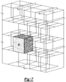
- FIG. 7 is part of core material (for a rotor or stator) with a cuboid cell arrangement.
- Laminated cores are made of thin laminations stamped from steel sheets of uniform and consistent thickness. The thickness is chosen as a compromise between cost, losses, and stacking factor. Thinner laminations result in more expensive cores, with lower losses, but also slightly lower torque capability because the insulation between the sheets takes proportionally more space with thinner laminations.
- additive manufacturing enables arrangements different than those suggested above.
- the insulating layers may be deposed more densely toward the inner surface of the core where the loss density is normally higher-simulating thin laminations.
- the insulation layers spacing is coarser toward the back, achieving a higher density of the flux carrying material (steel) resulting in higher torque capability. This is equivalent to an improved stacking factor for conventional laminated cores.
- very fine laminations 5 to 10% of the volume is occupied by the insulation between the lamination.
- the overall reluctance of the core is reduced leading to improved performance.
- Insulation layers may also be deposed in a honeycomb pattern or other polyhedral pattern, denser in areas of higher loss concentration and larger in other areas.
- the size of the honeycomb cell (or other equivalent structure) can be varied throughout to optimize the ratio of loss and amount of active material (steel).
- the amount of insulating material should be kept to a minimum to avoid higher reluctance (lower permeability) of the core, which limits magnetic flux penetration.
- the requirement to reduce losses may interfere with the strength requirements of the material.
- One example could be the thin portions between the magnet pockets and the outer edge of the rotor (bridges). The segmentation can be suspended in the bridge area to maintain a high yield stress and a high speed rating.
- a rotor and/or stator of an electric machine may have non-uniform core loss distribution.
- simulation of a portion of a rotor 10 containing permanent magnets 12 therein reveals regions of higher loss concentrations (textured) around outer periphery 14 near the airgap region between the rotor 10 and stator (not shown). These higher loss regions can undesirably affect performance of the electric machine. Depending on electric machine design, these areas may be larger or smaller, and be located in different or other regions.
- a stator 16 (and rotor) is typically constructed from a series of thin laminations 18 stamped from steel sheets of uniform consistent thickness.
- the thickness can be chosen as a compromise between cost, losses, and stacking factor. Thinner laminations result in more expensive cores, with lower losses, but also slightly lower torque capability because insulation 20 between each of the sheets 18 takes proportionally more space with thinner laminations.
- the requirement of reducing losses on the inner surface of the core (especially in rotors) conventionally determines how thin the laminations 18 should be.
- Some traditional manufacturing techniques involve a material being carved or shaped into the desired product by parts of it being removed. Laminations of a rotor or stator, for example, can be stamped from sheets of metal as mentioned above. Additive manufacturing, in some sense, is the opposite. Structures are made by the addition of a number of layers that combine to create the product. The process may involve the use of a computer and special software that can relay messages to the printer so that it “prints” the desired shape.
- a cartridge is loaded with the relevant substance, and this is “printed” into the shape, one wafer-thin layer at a time. These layers are repeatedly printed on top of each other, being fused together during the process until the shape is complete.
- the ability to selectively depose (print) discrete portions of electrical steel and insulating material, during stator or rotor manufacture allows the creation of components tailored to perform within their unique environment.
- the insulating layers can be printed more densely within those areas of the rotor or stator where the loss density is normally higher, simulating locally thin laminations.
- the insulative-layer spacing can be coarser elsewhere, achieving a higher density of the flux carrying material (steel) resulting in higher torque capability. This is equivalent to an improved stacking factor for conventional components.
- very fine laminations 5 to 10% of the volume is occupied by the insulation between the laminations.
- the reluctance of the rotor or stator is reduced leading to improved performance.
- a plurality of rings 22 are stacked to form a stator 24 .
- the stator 24 has an outer periphery 26 and a plurality of teeth 28 extending radially inward from the outer periphery 26 .
- Tooth portions 30 of each of the rings 22 each include a base 32 and a plurality of fins 34 (e.g., 5 fins) extending radially inward from the base 32 .
- Insulative material 36 is disposed between the fins 34 (and the rings 22 ). So arranged, the portions of the stator 24 collectively defined by the fins 34 have more insulative material on a per unit volume basis as compared with the bases 32 and outer periphery 26 .
- the insulative-layer spacing is coarser in the bases 32 and outer periphery 26 as compared with the portions of the stator 24 collectively defined by the fins 34 , which reduces the tendency of the stator 24 to experience higher core loss in the localized areas adjacent the rotor (rotor not shown) as the reluctance is relatively greater in these localized areas without unnecessarily impacting the overall performance of the stator 24 .
- printed layers 38 have discrete portions of electric steel 40 and discrete portions of insulative material 42 arranged to form a contiguous network of insulative boundaries 44 that separate discrete cells 46 of the electric steel deposed in a honeycomb pattern of hexagonal cylinders.
- the pattern can be more dense (smaller discrete cells) in areas of otherwise higher potential loss concentration to increase localized reluctance (shown for example in a rotor and stator in FIG. 6 ) and less dense (larger discrete cells) in other areas to reduce localized reluctance such that, for example, the volume of the discrete cells within the outer periphery of the stator 24 is greater than a volume of the discrete cells within the teeth.
- honeycomb cells 46 can be varied throughout the structure to optimize the ratio of loss and amount of active material (steel). As described above, the overall amount of insulating material 42 should be kept to a minimum to avoid overall higher reluctance (lower permeability) of the core which limits magnetic flux penetration.
- discrete cells 47 may instead have different and/or irregular shapes.
- a rotor 48 could have a requirement to reduce core losses around its outer periphery 50 while at the same time achieving certain strength requirements in portions 52 between magnet pockets 54 and the outer periphery 50 .
- the rotor 48 and stator 24 respectively have areas of finer segmentation 56 , 58 as discussed above.
- the areas of finer segmentation 56 can be suspended in the bridge areas 52 to maintain a high yield stress and a high speed rating.
- discrete cells 60 may have cuboid shapes.
- Additive manufacturing systems can be used to create the components contemplated herein.
- the corresponding processes, methods, or algorithms to create these components can be deliverable to/implemented by a processing device, controller, or computer, which can include any existing programmable electronic control unit or dedicated electronic control unit.
- the processes, methods, or algorithms can be stored as data and instructions executable by a controller or computer in many forms including, but not limited to, information permanently stored on non-writable storage media such as Read Only Memory (ROM) devices and information alterably stored on writeable storage media such as floppy disks, magnetic tapes, Compact Discs (CDs), Random Access Memory (RAM) devices, and other magnetic and optical media.
- ROM Read Only Memory
- CDs Compact Discs
- RAM Random Access Memory
- the processes, methods, or algorithms can also be implemented in a software executable object.
- the processes, methods, or algorithms can be embodied in whole or in part using suitable hardware components, such as Application Specific Integrated Circuits (ASICs), Field-Programmable Gate Arrays (FPGAs), state machines, controllers or other hardware components or devices, or a combination of hardware, software, and firmware components.
- ASICs Application Specific Integrated Circuits
- FPGAs Field-Programmable Gate Arrays
- state machines controllers or other hardware components or devices, or a combination of hardware, software, and firmware components.
- These attributes may include, but are not limited to cost, strength, durability, life cycle cost, marketability, appearance, packaging, size, serviceability, weight, manufacturability, ease of assembly, etc. As such, embodiments described as less desirable than other embodiments or prior art implementations with respect to one or more characteristics are not outside the scope of the disclosure and can be desirable for particular applications.
Landscapes
- Engineering & Computer Science (AREA)
- Power Engineering (AREA)
- Manufacturing & Machinery (AREA)
- Mechanical Engineering (AREA)
- Chemical & Material Sciences (AREA)
- Materials Engineering (AREA)
- Iron Core Of Rotating Electric Machines (AREA)
Abstract
Description
Claims (14)
Priority Applications (3)
| Application Number | Priority Date | Filing Date | Title |
|---|---|---|---|
| US16/598,698 US11557947B2 (en) | 2019-10-10 | 2019-10-10 | Stators and rotors with varying insulative density |
| DE102020126459.3A DE102020126459A1 (en) | 2019-10-10 | 2020-10-08 | STATORS AND ROTORS WITH VARIABLE INSULATION DENSITY |
| CN202011081252.3A CN112653259A (en) | 2019-10-10 | 2020-10-09 | Stator and rotor with different insulation densities |
Applications Claiming Priority (1)
| Application Number | Priority Date | Filing Date | Title |
|---|---|---|---|
| US16/598,698 US11557947B2 (en) | 2019-10-10 | 2019-10-10 | Stators and rotors with varying insulative density |
Publications (2)
| Publication Number | Publication Date |
|---|---|
| US20210111613A1 US20210111613A1 (en) | 2021-04-15 |
| US11557947B2 true US11557947B2 (en) | 2023-01-17 |
Family
ID=75155645
Family Applications (1)
| Application Number | Title | Priority Date | Filing Date |
|---|---|---|---|
| US16/598,698 Active 2041-04-09 US11557947B2 (en) | 2019-10-10 | 2019-10-10 | Stators and rotors with varying insulative density |
Country Status (3)
| Country | Link |
|---|---|
| US (1) | US11557947B2 (en) |
| CN (1) | CN112653259A (en) |
| DE (1) | DE102020126459A1 (en) |
Families Citing this family (1)
| Publication number | Priority date | Publication date | Assignee | Title |
|---|---|---|---|---|
| DE102021119405A1 (en) | 2021-05-27 | 2022-12-01 | Additive Drives GmbH | Stator for an electric machine, electric machine, stator cooling system and method for cooling a stator |
Citations (6)
| Publication number | Priority date | Publication date | Assignee | Title |
|---|---|---|---|---|
| US8456057B2 (en) | 2009-12-01 | 2013-06-04 | Mitsui High-Tec, Inc. | Laminated stator core |
| US9419502B2 (en) | 2012-08-03 | 2016-08-16 | Hamilton Sundstrand Corporation | Additive manufacturing of a component having a laminated stack of layers |
| US20180205285A1 (en) | 2017-01-13 | 2018-07-19 | Ge Aviation Systems Llc | Method for manufacturing an integrated stator and housing for an electrical machine |
| US20180205299A1 (en) * | 2017-01-13 | 2018-07-19 | Ge Aviation Systems Llc | Method for manufacturing a stator assembly of an electrical machine |
| US20180233997A1 (en) * | 2017-02-16 | 2018-08-16 | Honda Motor Co., Ltd. | Core for rotary electric machine and method of manufacturing the same |
| WO2020247326A1 (en) * | 2019-06-05 | 2020-12-10 | Milwaukee Electric Tool Corporation | Electric motor |
-
2019
- 2019-10-10 US US16/598,698 patent/US11557947B2/en active Active
-
2020
- 2020-10-08 DE DE102020126459.3A patent/DE102020126459A1/en active Pending
- 2020-10-09 CN CN202011081252.3A patent/CN112653259A/en active Pending
Patent Citations (6)
| Publication number | Priority date | Publication date | Assignee | Title |
|---|---|---|---|---|
| US8456057B2 (en) | 2009-12-01 | 2013-06-04 | Mitsui High-Tec, Inc. | Laminated stator core |
| US9419502B2 (en) | 2012-08-03 | 2016-08-16 | Hamilton Sundstrand Corporation | Additive manufacturing of a component having a laminated stack of layers |
| US20180205285A1 (en) | 2017-01-13 | 2018-07-19 | Ge Aviation Systems Llc | Method for manufacturing an integrated stator and housing for an electrical machine |
| US20180205299A1 (en) * | 2017-01-13 | 2018-07-19 | Ge Aviation Systems Llc | Method for manufacturing a stator assembly of an electrical machine |
| US20180233997A1 (en) * | 2017-02-16 | 2018-08-16 | Honda Motor Co., Ltd. | Core for rotary electric machine and method of manufacturing the same |
| WO2020247326A1 (en) * | 2019-06-05 | 2020-12-10 | Milwaukee Electric Tool Corporation | Electric motor |
Also Published As
| Publication number | Publication date |
|---|---|
| DE102020126459A1 (en) | 2021-04-15 |
| US20210111613A1 (en) | 2021-04-15 |
| CN112653259A (en) | 2021-04-13 |
Similar Documents
| Publication | Publication Date | Title |
|---|---|---|
| EP2888806B1 (en) | Rotor with magnet pattern | |
| JP2003339128A (en) | Motor, stator core, rotor core, motor manufacturing method, stator core manufacturing method, and rotor core manufacturing method | |
| JP2012115129A (en) | Rotor of synchronous reluctance machine and method for manufacturing rotor of synchronous reluctance machine | |
| US20100253169A1 (en) | Electric machine | |
| US20140070638A1 (en) | Coil assembly for three phased transverse axial flux multi disk machines | |
| JP6056385B2 (en) | Rotor for rotating machine and method for manufacturing rotor for rotating machine | |
| JP2013110827A (en) | Rotor structure of motor | |
| CN104283386A (en) | Axial gap type permanent magnet electric rotating apparatus and method of manufacturing the same | |
| JP2018113775A (en) | Dynamo-electric machine rotor | |
| US9777770B2 (en) | Active part of an electrical machine, radial magnetic bearing and method for producing a radial magnetic bearing | |
| US8222787B2 (en) | Electric machine | |
| US20060061226A1 (en) | Permanent magnet-type motor | |
| US11557947B2 (en) | Stators and rotors with varying insulative density | |
| JP2001025189A (en) | Permanent magnet rotor permanent magnet | |
| JP2018129938A (en) | Rotating electric machine | |
| CN202340171U (en) | Power generation device | |
| JP6687272B1 (en) | Rotating electric machine and method for manufacturing core | |
| JP2014226023A (en) | Stator of sr motor, and sr motor including this stator | |
| EP0056272B1 (en) | Method for preparation of a laminated iron core and laminated iron core of an electric device | |
| CN107046352B (en) | Internal permanent magnet motor | |
| JP2006014565A (en) | Disk type rotating electrical machine | |
| JP2005304193A (en) | Permanent magnet rotor and manufacturing method thereof | |
| US20230048820A1 (en) | Rotor core design | |
| WO2022080103A1 (en) | Laminated iron core and electric motor provided with same | |
| JPWO2022080103A5 (en) |
Legal Events
| Date | Code | Title | Description |
|---|---|---|---|
| AS | Assignment |
Owner name: FORD GLOBAL TECHNOLOGIES, LLC, MICHIGAN Free format text: ASSIGNMENT OF ASSIGNORS INTEREST;ASSIGNORS:LEONARDI, FRANCO;DEGNER, MICHAEL W.;SIGNING DATES FROM 20191003 TO 20191004;REEL/FRAME:050683/0604 |
|
| FEPP | Fee payment procedure |
Free format text: ENTITY STATUS SET TO UNDISCOUNTED (ORIGINAL EVENT CODE: BIG.); ENTITY STATUS OF PATENT OWNER: LARGE ENTITY |
|
| STPP | Information on status: patent application and granting procedure in general |
Free format text: DOCKETED NEW CASE - READY FOR EXAMINATION |
|
| STPP | Information on status: patent application and granting procedure in general |
Free format text: PRE-INTERVIEW COMMUNICATION MAILED |
|
| STPP | Information on status: patent application and granting procedure in general |
Free format text: RESPONSE TO NON-FINAL OFFICE ACTION ENTERED AND FORWARDED TO EXAMINER |
|
| STPP | Information on status: patent application and granting procedure in general |
Free format text: NON FINAL ACTION MAILED |
|
| STPP | Information on status: patent application and granting procedure in general |
Free format text: RESPONSE TO NON-FINAL OFFICE ACTION ENTERED AND FORWARDED TO EXAMINER |
|
| STPP | Information on status: patent application and granting procedure in general |
Free format text: NOTICE OF ALLOWANCE MAILED -- APPLICATION RECEIVED IN OFFICE OF PUBLICATIONS |
|
| STPP | Information on status: patent application and granting procedure in general |
Free format text: AWAITING TC RESP., ISSUE FEE NOT PAID |
|
| STPP | Information on status: patent application and granting procedure in general |
Free format text: NOTICE OF ALLOWANCE MAILED -- APPLICATION RECEIVED IN OFFICE OF PUBLICATIONS |
|
| STPP | Information on status: patent application and granting procedure in general |
Free format text: PUBLICATIONS -- ISSUE FEE PAYMENT VERIFIED |
|
| STCF | Information on status: patent grant |
Free format text: PATENTED CASE |