US11557884B2 - Fixture aligner - Google Patents
Fixture aligner Download PDFInfo
- Publication number
- US11557884B2 US11557884B2 US16/426,143 US201916426143A US11557884B2 US 11557884 B2 US11557884 B2 US 11557884B2 US 201916426143 A US201916426143 A US 201916426143A US 11557884 B2 US11557884 B2 US 11557884B2
- Authority
- US
- United States
- Prior art keywords
- sleeve
- fixture
- aligner
- connector
- cable connector
- Prior art date
- Legal status (The legal status is an assumption and is not a legal conclusion. Google has not performed a legal analysis and makes no representation as to the accuracy of the status listed.)
- Active, expires
Links
- 238000000034 method Methods 0.000 claims description 34
- 230000003416 augmentation Effects 0.000 claims description 6
- 239000000853 adhesive Substances 0.000 claims description 5
- 230000001070 adhesive effect Effects 0.000 claims description 5
- 238000010146 3D printing Methods 0.000 claims description 3
- 239000003550 marker Substances 0.000 claims description 3
- 239000000463 material Substances 0.000 description 5
- 238000004519 manufacturing process Methods 0.000 description 3
- 239000002184 metal Substances 0.000 description 3
- VNWKTOKETHGBQD-UHFFFAOYSA-N methane Chemical compound C VNWKTOKETHGBQD-UHFFFAOYSA-N 0.000 description 3
- 229920000049 Carbon (fiber) Polymers 0.000 description 2
- 239000004917 carbon fiber Substances 0.000 description 2
- 238000010276 construction Methods 0.000 description 2
- 238000005336 cracking Methods 0.000 description 2
- 238000005516 engineering process Methods 0.000 description 2
- 230000003287 optical effect Effects 0.000 description 2
- 239000004033 plastic Substances 0.000 description 2
- 239000000654 additive Substances 0.000 description 1
- 230000000996 additive effect Effects 0.000 description 1
- 238000005266 casting Methods 0.000 description 1
- 239000011248 coating agent Substances 0.000 description 1
- 238000000576 coating method Methods 0.000 description 1
- 239000002131 composite material Substances 0.000 description 1
- 238000000748 compression moulding Methods 0.000 description 1
- 238000011960 computer-aided design Methods 0.000 description 1
- 238000013461 design Methods 0.000 description 1
- 238000010586 diagram Methods 0.000 description 1
- 238000010101 extrusion blow moulding Methods 0.000 description 1
- 238000010102 injection blow moulding Methods 0.000 description 1
- 238000001746 injection moulding Methods 0.000 description 1
- 238000003780 insertion Methods 0.000 description 1
- 230000037431 insertion Effects 0.000 description 1
- 238000012986 modification Methods 0.000 description 1
- 230000004048 modification Effects 0.000 description 1
- 238000010107 reaction injection moulding Methods 0.000 description 1
- 230000003362 replicative effect Effects 0.000 description 1
- 238000001175 rotational moulding Methods 0.000 description 1
- 238000005070 sampling Methods 0.000 description 1
- 238000003856 thermoforming Methods 0.000 description 1
- 238000012546 transfer Methods 0.000 description 1
Images


Classifications
-
- H—ELECTRICITY
- H01—ELECTRIC ELEMENTS
- H01R—ELECTRICALLY-CONDUCTIVE CONNECTIONS; STRUCTURAL ASSOCIATIONS OF A PLURALITY OF MUTUALLY-INSULATED ELECTRICAL CONNECTING ELEMENTS; COUPLING DEVICES; CURRENT COLLECTORS
- H01R43/00—Apparatus or processes specially adapted for manufacturing, assembling, maintaining, or repairing of line connectors or current collectors or for joining electric conductors
- H01R43/26—Apparatus or processes specially adapted for manufacturing, assembling, maintaining, or repairing of line connectors or current collectors or for joining electric conductors for engaging or disengaging the two parts of a coupling device
-
- H—ELECTRICITY
- H02—GENERATION; CONVERSION OR DISTRIBUTION OF ELECTRIC POWER
- H02G—INSTALLATION OF ELECTRIC CABLES OR LINES, OR OF COMBINED OPTICAL AND ELECTRIC CABLES OR LINES
- H02G1/00—Methods or apparatus specially adapted for installing, maintaining, repairing or dismantling electric cables or lines
Definitions
- aspects of the present disclosure relate to cables or cords, more particular aspects relate to cable connectors.
- Electrical cords or cables and their connectors define physical parameters for the transfer and interpretation of signals. For some signals (digital audio and digital video), this can be thought of as defining the physical layer, data link layer, and most or all of the application layer. For analog audio and analog video these functions are all represented in a single signal specification or the direct speaker-driving signal of analog audio. Physical characteristics of the electrical or optical equipment includes the types and numbers of wires required, voltages, frequencies, optical intensity, and the physical design of the connectors.
- the apparatus includes a sleeve configured to receive a cable connector, a first opening at a first end of the sleeve, a second opening at a second end of the sleeve. wherein the sleeve is designed to receive the cable connector through the first end and allow the cable connector to exit through the second end after the cable connector has been engaged to a port, a channel extending a length of the sleeve from the first end to the second end, designed to allow for a cord attached to the cable connector to pass through the channel, and a handle extending from the first end of the sleeve.
- the method includes placing a fixture aligner over a port, inserting a connector into the fixture aligner, engaging the connector with the port, and sliding the fixture aligner off of the connector away from the port.
- the method includes forming a sleeve designed to receive a cable connector with a first opening at a first end of the sleeve and a second opening at a second end of the sleeve, the sleeve designed to receive the cable connector through the first end and allow the cable connector to exit through the second end after the cable connector has been engaged to a port, establishing a channel in the sleeve extending a length of the sleeve from the first end to the second end, the channel designed to allow for a cord attached to the cable connector to pass through the channel, and forming a handle that extends from the first end of the sleeve.
- FIG. 1 is a diagram illustrating a fixture aligner and a connector.
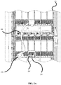
- FIG. 2 A illustrates an example placement of a fixture aligner on a computer.
- FIG. 2 B illustrates an example placement of a fixture aligner on a computer with a connector being inserted.
- FIG. 2 C illustrates an example placement of a fixture aligner on a computer after a connector has been engaged.
- FIG. 3 A illustrates an example fixture aligner
- FIG. 3 B illustrates an example fixture aligner
- FIG. 3 C illustrates an example fixture aligner
- FIG. 4 illustrates an example method for designing a fixture aligner.
- FIG. 5 illustrates an example method for making a fixture aligner.
- FIG. 6 illustrates an example method for using a fixture aligner to engage a connector.
- FIG. 7 illustrates an example method for using a fixture aligner to disengage a connector.
- connection devices may be described as a connector (e.g., plug) or a port (e.g., socket, connector, or any other construction able to receive a connector).
- a connector e.g., plug
- a port e.g., socket, connector, or any other construction able to receive a connector.
- an ethernet cable ends in a connector and a computer may have an ethernet port.
- the port may be on the back of a computing device, such as a computer server. Describing the connector on the end of a cable and the port on the back of a computer is meant as a descriptive example.
- the port may be on another cable, a server, a battery backup, or any other electronic device.
- either the cable or the port may have protruding connectors or any other means of making an electronic, signal, or data connection.
- FIG. 1 depicts an example fixture aligner 100 apparatus and an example connector 150 .
- fixture aligner 100 is designed such that connector 150 can slide through fixture aligner 100 .
- fixture aligner 100 is designed with a sleeve 110 designed to fit around connector 150 .
- sleeve 110 has a slit 111 .
- Slit 111 may be designed to accommodate a cord (e.g., a ribbon cable, an either net cable, a power cord, etc.) connected to connector 150 .
- slit 111 can be designed to allow a ribbon cable attached to the side of connector 150 to slide through it.
- sleeve 110 has a first end 115 and a second end 116 .
- fixture aligner 100 has a handle 105 .
- handle 105 may be designed to be held by hand while using fixture aligner 100 .
- handle 105 has grip augmentation feature 106 .
- grip augmentation feature 106 takes the form of a hole, but in some embodiments grip augmentation feature 106 may take other forms.
- a grip augmentation feature may be bumps or a coating.
- fixture aligner 200 designed to accommodate connector 250 and a cord 280 , is placed on the back of computer 290 around a port 295 .
- fixture aligner 200 is held in place by a handle (such as handle 105 ).
- fixture aligner 200 is capable of being visually inspected to ensure that it is aligned with port 295 .
- fixture aligner 200 may be designed to fit in or along a feature of port 295 or around port 295 . For example, if there is a grove on computer 290 above port 295 , fixture aligner 200 may be designed such that a part of fixture aligner 200 fits inside of the groove.
- a of fixture aligner 200 may be designed with alignment features. For example, if computer 290 has holes or notches near port 295 , fixture aligner 200 may have pins or pegs designed to fit inside the holes or notches.
- an adhesive may be applied at one or more contact points of fixture aligner 200 .
- a small amount of non-permanent adhesive may be applied to an edge of fixture aligner 200 that is designed to be placed against computer 290 .
- no adhesive may be applied to fixture aligner 200 .
- an orientation marker may be placed on the fixture aligner to facilitate orientation during placement of the fixture aligner.
- a mark may be placed on fixture aligner 200 to indicate which direction is up.
- fixture aligner 200 has a slit (such as slit 111 ) to accommodate cord 280 .
- cord 280 is depicted as a ribbon cable and fixture aligner 200 is designed to fit around cord 280 without impeding or obstructing the engagement (e.g., plug in or connect) or disengagement (e.g., unplug or disconnect) of connector 250 .
- the handle of fixture aligner 200 may be held during the insertion of connector 250 .
- Fixture aligner 200 may help to safeguard against connector 250 being connected to or disconnected from a port at an improper angle or rotated such that the connector and/or port are damaged.
- fixture aligner 200 may be designed to flex around connector 250 .
- fixture aligner 200 may be made out of a flexible material and made slightly smaller than connector 250 such that fixture aligner 200 flexes around connector 250 when connector 250 is inserted into fixture aligner 200 .
- fixture aligner 200 may be removed by grasping the handle of fixture aligner 200 .
- fixture aligner 200 may be removed after the action of engaging or disengaging connector 250 .
- fixture aligner 200 may be pulled away from computer 290 .
- Fixture aligner 200 may slide over connector 250 away from computer 290 .
- FIGS. 3 A, 3 B, and 3 C An example fixture aligner 300 is depicted in FIGS. 3 A, 3 B, and 3 C .
- FIG. 3 B is a side view of fixture aligner 300 as viewed from A in FIG. 3 A .
- FIG. 3 C is a bottom view of fixture aligner 300 as viewed from B in FIG. 3 A .
- example fixture aligner 300 has an overall length 305 and a sleeve length 310 .
- overall length 305 may be approximately 115 mm+/ ⁇ 2 mm
- sleeve length 310 may be 38 mm+/ ⁇ 2 mm.
- example fixture aligner 300 has a grip hole length 315 and a grip hole width of 316 .
- grip hole length may be 30 mm+/ ⁇ 2 mm and grip hole width may be 15.5 mm+/ ⁇ 2 mm.
- example fixture aligner 300 has a handle length of 307 .
- Handle length 307 can be varied according to a particular application's needs. For example, a fixture aligner in a densely packed system with many wires may need a longer handle to avoid entanglement with cords going to neighboring connectors.
- the handle (or some sections of the handle) may be thicker to facilitate grasping by a hand, or to increase the structural integrity of the handle. For example, a section of the handle near the sleeve may be twice the thickness of the rest of the handle.
- example fixture aligner 300 has an internal cavity body depth 325 , an internal cavity body width 320 , a slit width 330 , a side wall thicknesses 340 , and a back wall thickness 345 .
- internal cavity depth 325 and internal cavity width 320 may be designed to accommodate a specific connector.
- internal cavity depth 325 may be 38 mm+/ ⁇ 2 mm and internal cavity width 320 may be 21 mm+/ ⁇ 2 mm to accommodate a connector that has a depth of approximately 27 mm and a width of approximately 20 mm.
- wall thicknesses of fixture aligner 300 may vary.
- a back wall thickness 345 may be thicker than side wall thickness 340 to add more rigidity to the portion of fixture aligner 300 that connects to a handle (such as handle 105 ).
- back wall thickness 345 may be 4.9 mm+/ ⁇ 0.5 mm and side wall thickness 340 may be 2.95 mm+/ ⁇ 0.5 mm.
- the wall thickness of fixture aligner 300 may be varied to address structural demands. For example, parts of fixture aligner 300 that are prone to cracking may be made thicker and parts that are not prone to cracking may be made thinner.
- a slit width 330 may be designed to allow a cord, such as cord 280 , to slide through slit width 330 during use of fixture aligner 300 .
- slit width 330 may be 8 mm+/ ⁇ 1 mm to accommodate a cord with a thickness of up to 7 mm.
- dimensions are designed according to structural needs (e.g., strength, modulus, etc.), fabrication considerations (e.g., moldability, assembly, etc.), and/or cost considerations.
- the dimensions, angles, orientations, configurations, and other interrelationships shown in FIG. 3 A- 3 C are not to be taken in a limiting sense, and are not meant to be construed as necessarily replicating, or even approximating, the dimensions, angles, orientations, configurations, and other possible interrelationships that may be realized in a fixture aligner falling within the spirit and scope of the present disclosure.
- FIG. 4 illustrates a flowchart of an example method 400 of designing a fixture aligner.
- the dimensions of a connector are determined at block 410 .
- the opening of a fixture aligner may be slightly larger (e.g., 1 mm in width and depth) than the connector it was designed for so the connector can slide freely through the fixture aligner.
- the connector may have a cord coming off of a side of the connector (such as cord 280 ) or it may have a cord extending from a face opposite of the engagement portion of the connector.
- the dimensions of a sleeve of the fixture aligner are determined such that the fixture aligner accommodates the connector and cord.
- slit width 330 from FIG. 3 C may accommodate cord 280 from FIG. 2 A .
- the placement of a slit may accommodate the movement of the cord and therefore may need to be specifically placed on one wall of the fixture aligner.
- the slit may be placed in the most convenient or structurally sound place on the fixture aligner.
- a handle length for the fixture is specified.
- a longer handle e.g., greater than 77 mm
- a shorter handle e.g., less than 77 mm
- a tight working space may be specified.
- a thickness of each part of the fixture is determined.
- the wall thickness may be uniform throughout the part.
- the handles, or the region around a handle sleeve interface may be thicker.
- specific regions of the sleeve may be designed to be thinner to allow the sleeve to flex around a connector. For example, where the entire sleeve is made out of the same material, thinner regions may have less rigidity and therefor may allow the sleeve to bend more in the thinner regions than the thicker regions.
- FIG. 5 illustrates a flowchart of an example method 500 of producing a fixture aligner.
- a sleeve is formed at block 510 .
- the sleeve contains a first opening at a first end (e.g., first end 115 in FIG. 1 ) of the sleeve and a second opening at the second end (e.g., second end 116 in FIG. 1 ) of the sleeve and the sleeve is designed to receive a cable connector.
- the sleeve may be designed to receive a cable connector through the first end (while the sleeve is held at a port) and allow the cable connector to exit through the second end after the cable connector has been engaged to a port when the sleeve is pulled away from the port.
- the sleeve is designed to be placed over a cable connector while the connector is engaged, where the sleeve contains first opening at a first end of the sleeve and a second opening at the second end of the sleeve.
- the sleeve is designed to receive a cable connector through the second end while the connector is engaged and allow the cable connector to exit through the second end after the cable connector has been disengaged from a port.
- a channel is established in the sleeve extending a length of the sleeve from the first end to the second end, designed to allow for a cord attached to the cable connector to pass through the channel.
- the sleeve could be formed without material in the region of the channel, or the sleeve could be formed with material in the cannel and the material could be removed forming the channel.
- a handle that extends from the first end of the sleeve is formed.
- blocks 510 , 520 , and 530 may be performed simultaneously.
- blocks 510 , 520 , and 530 may include forming parts separately and assembling the parts together. For example, a sleeve could be formed, a slit could be cut in the sleeve, and then a handle could be glued to the sleeve.
- the fixture aligner may be formed with a rapid prototyping technique such as stereolithography and/or 3D printing. Rapid prototyping is a group of techniques used to quickly fabricate a physical part or assembly using three-dimensional computer aided design. Construction of the part or assembly may be performed using 3D printing or “additive layer manufacturing” technology.
- the fixture aligner may be formed of a plastic, metal, carbon fiber, and/or composite material.
- the fixture aligner may be formed using plastic injection molding, rotational molding, extrusion blow molding, injection blow molding, reaction injection molding, vacuum casting, thermoforming, and/or compression molding, among other techniques.
- a metal part may be fabricated using a metal sampling and folding technique.
- a carbon fiber part could be fabricated using a carbon fiber laminate over a mold.
- FIG. 6 illustrates a flowchart of an example method 600 of using a fixture aligner to engage a connector.
- the fixture aligner is placed around a port at block 610 .
- the fixture aligner may be visually inspected during the placement.
- the fixture aligner is placed on the surface containing the port.
- the fixture aligner is designed to accommodate a cable connected to the connector.
- a connector may be inserted into the fixture aligner.
- the connector may be aligned with the fixture aligner such that the cord is oriented towards a slit on the fixture aligner.
- the connector may be engaged with the port.
- the connector may be slid through a sleeve of the fixture aligner to engage the connector with the port.
- the fixture aligner may be slid off of the connector away from the port.
- the cord may slide through the slit on the fixture aligner.
- FIG. 7 illustrates a flowchart of an example method 700 of using a fixture aligner to disengage a connector.
- the fixture aligner is placed around a connector at block 710 , where the connector is engaged to a port.
- the fixture aligner may be visually inspected during the placement.
- the fixture aligner is designed to accommodate a cable connected to the connector.
- the connector may be disengaged from the port.
- the connector may be pulled by a tab attached to the connector in order to disengage the connector from the port.
- the connector may be removed from the port.
- the connector may be slid through a sleeve of the fixture aligner to remove the connector from the fixture aligner.
- the fixture aligner and the connector may be removed in unison.
- the cord may slide through the slit on the fixture aligner.
Landscapes
- Engineering & Computer Science (AREA)
- Manufacturing & Machinery (AREA)
- Details Of Connecting Devices For Male And Female Coupling (AREA)
Abstract
Description
Claims (20)
Priority Applications (1)
| Application Number | Priority Date | Filing Date | Title |
|---|---|---|---|
| US16/426,143 US11557884B2 (en) | 2019-05-30 | 2019-05-30 | Fixture aligner |
Applications Claiming Priority (1)
| Application Number | Priority Date | Filing Date | Title |
|---|---|---|---|
| US16/426,143 US11557884B2 (en) | 2019-05-30 | 2019-05-30 | Fixture aligner |
Publications (2)
| Publication Number | Publication Date |
|---|---|
| US20200381904A1 US20200381904A1 (en) | 2020-12-03 |
| US11557884B2 true US11557884B2 (en) | 2023-01-17 |
Family
ID=73551453
Family Applications (1)
| Application Number | Title | Priority Date | Filing Date |
|---|---|---|---|
| US16/426,143 Active 2041-05-28 US11557884B2 (en) | 2019-05-30 | 2019-05-30 | Fixture aligner |
Country Status (1)
| Country | Link |
|---|---|
| US (1) | US11557884B2 (en) |
Citations (13)
| Publication number | Priority date | Publication date | Assignee | Title |
|---|---|---|---|---|
| US3068316A (en) * | 1959-06-12 | 1962-12-11 | Witt Governor | Cord shortening holder |
| US3852517A (en) * | 1972-06-12 | 1974-12-03 | Raychem Corp | Conductive insert for heat recoverable electrical connector |
| US5619569A (en) * | 1995-05-19 | 1997-04-08 | Mcvay; Clifford R. | Coil cord snarl preventing device and method |
| US6683252B2 (en) * | 1999-03-11 | 2004-01-27 | Alcatel Canada Inc. | Latching device for a circuit pack |
| US20100040330A1 (en) * | 2007-05-21 | 2010-02-18 | At&T Intellectual Property I, L.P. | Optical fiber connection system |
| US20100278497A1 (en) * | 2009-05-01 | 2010-11-04 | Advanced Connectek Inc. | Optical fiber connector adapter |
| US8039750B2 (en) * | 2008-11-12 | 2011-10-18 | Sony Ericsson Mobile Communications Ab | Cable connector having length adjustability |
| MX2011004213A (en) | 2010-04-20 | 2011-10-28 | Thomas & Betts Int | Electrical connector having alignment mechanism. |
| US8528171B2 (en) * | 2009-01-30 | 2013-09-10 | Elionne LaMar Walker | Apparatus for storing and organizing electrical cords |
| US8793842B2 (en) * | 2012-11-02 | 2014-08-05 | Valerie M. T. Donovan | Cord management sleeve |
| US20140305700A1 (en) * | 2011-06-21 | 2014-10-16 | Adc Telecommunications, Inc. | Connector with slideable retention feature and patch cord having the same |
| US20140315414A1 (en) | 2013-04-17 | 2014-10-23 | Hon Hai Precision Industry Co., Ltd. | Plug tool for plugging or unplugging connector |
| CN109188611A (en) | 2018-09-03 | 2019-01-11 | 华为技术有限公司 | Optical fiber connector and optical fiber connector |
-
2019
- 2019-05-30 US US16/426,143 patent/US11557884B2/en active Active
Patent Citations (13)
| Publication number | Priority date | Publication date | Assignee | Title |
|---|---|---|---|---|
| US3068316A (en) * | 1959-06-12 | 1962-12-11 | Witt Governor | Cord shortening holder |
| US3852517A (en) * | 1972-06-12 | 1974-12-03 | Raychem Corp | Conductive insert for heat recoverable electrical connector |
| US5619569A (en) * | 1995-05-19 | 1997-04-08 | Mcvay; Clifford R. | Coil cord snarl preventing device and method |
| US6683252B2 (en) * | 1999-03-11 | 2004-01-27 | Alcatel Canada Inc. | Latching device for a circuit pack |
| US20100040330A1 (en) * | 2007-05-21 | 2010-02-18 | At&T Intellectual Property I, L.P. | Optical fiber connection system |
| US8039750B2 (en) * | 2008-11-12 | 2011-10-18 | Sony Ericsson Mobile Communications Ab | Cable connector having length adjustability |
| US8528171B2 (en) * | 2009-01-30 | 2013-09-10 | Elionne LaMar Walker | Apparatus for storing and organizing electrical cords |
| US20100278497A1 (en) * | 2009-05-01 | 2010-11-04 | Advanced Connectek Inc. | Optical fiber connector adapter |
| MX2011004213A (en) | 2010-04-20 | 2011-10-28 | Thomas & Betts Int | Electrical connector having alignment mechanism. |
| US20140305700A1 (en) * | 2011-06-21 | 2014-10-16 | Adc Telecommunications, Inc. | Connector with slideable retention feature and patch cord having the same |
| US8793842B2 (en) * | 2012-11-02 | 2014-08-05 | Valerie M. T. Donovan | Cord management sleeve |
| US20140315414A1 (en) | 2013-04-17 | 2014-10-23 | Hon Hai Precision Industry Co., Ltd. | Plug tool for plugging or unplugging connector |
| CN109188611A (en) | 2018-09-03 | 2019-01-11 | 华为技术有限公司 | Optical fiber connector and optical fiber connector |
Also Published As
| Publication number | Publication date |
|---|---|
| US20200381904A1 (en) | 2020-12-03 |
Similar Documents
| Publication | Publication Date | Title |
|---|---|---|
| US8507796B2 (en) | Ribbon Cables | |
| US20140331464A1 (en) | Coupling housing connector pull tab | |
| TWI580125B (en) | Communication plug with improved cable management | |
| US9337594B2 (en) | Hermaphroditic electrical connector device with additional contact elements | |
| US10495828B2 (en) | Optical fiber connector | |
| US20110256756A1 (en) | Diiva, displayport, dvi, usb, and hdmi diy field termination products | |
| US7862384B2 (en) | Repair adapter for a modular plug | |
| TWM318226U (en) | Structure for fast connection of waterproof cable connector | |
| US7896683B1 (en) | Connector assemblies configured to prevent damage to contacts during mating and demating | |
| US10156685B2 (en) | Optical fiber connector | |
| CN207282820U (en) | A kind of anti-dropout data cable connector | |
| JPH08510863A (en) | Multi-connector backshell | |
| US10133009B1 (en) | Fiber optic adaptor | |
| CN104241927A (en) | Connector housing | |
| CN105247740A (en) | Grouped Cavity Housings for Coaxial Cable Connectors | |
| US11557884B2 (en) | Fixture aligner | |
| CN104396088B (en) | RJ45 connector with wire guiding device | |
| US20110028023A1 (en) | Cable Connector Apparatus | |
| US11099336B2 (en) | Optical fiber connector | |
| CN105789957A (en) | Double-sided dual-purpose forward and reverse plugging connector | |
| US20120231642A1 (en) | Cable system with integrated adaptor | |
| US9401577B2 (en) | RJ-45 insertion and extraction tool | |
| US20140329402A1 (en) | Securing member for a connector | |
| US8157455B2 (en) | Optical connector | |
| CN209217329U (en) | Quick connector |
Legal Events
| Date | Code | Title | Description |
|---|---|---|---|
| AS | Assignment |
Owner name: INTERNATIONAL BUSINESS MACHINES CORPORATION, NEW YORK Free format text: ASSIGNMENT OF ASSIGNORS INTEREST;ASSIGNORS:CORDERO LOZANO, SERGIO ALBERTO;IBARRA HERNANDEZ, JESUS ERNESTO;FLORES PANTOJA, OSCAR EDUARDO;REEL/FRAME:049317/0123 Effective date: 20190528 |
|
| FEPP | Fee payment procedure |
Free format text: ENTITY STATUS SET TO UNDISCOUNTED (ORIGINAL EVENT CODE: BIG.); ENTITY STATUS OF PATENT OWNER: LARGE ENTITY |
|
| STPP | Information on status: patent application and granting procedure in general |
Free format text: NON FINAL ACTION MAILED |
|
| STPP | Information on status: patent application and granting procedure in general |
Free format text: RESPONSE TO NON-FINAL OFFICE ACTION ENTERED AND FORWARDED TO EXAMINER |
|
| STPP | Information on status: patent application and granting procedure in general |
Free format text: NOTICE OF ALLOWANCE MAILED -- APPLICATION RECEIVED IN OFFICE OF PUBLICATIONS |
|
| STPP | Information on status: patent application and granting procedure in general |
Free format text: PUBLICATIONS -- ISSUE FEE PAYMENT VERIFIED |
|
| STCF | Information on status: patent grant |
Free format text: PATENTED CASE |