US11552399B2 - Split-ring resonator, board and connector - Google Patents
Split-ring resonator, board and connector Download PDFInfo
- Publication number
- US11552399B2 US11552399B2 US17/046,519 US201917046519A US11552399B2 US 11552399 B2 US11552399 B2 US 11552399B2 US 201917046519 A US201917046519 A US 201917046519A US 11552399 B2 US11552399 B2 US 11552399B2
- Authority
- US
- United States
- Prior art keywords
- split
- ring resonator
- conductor
- ground terminal
- present disclosure
- Prior art date
- Legal status (The legal status is an assumption and is not a legal conclusion. Google has not performed a legal analysis and makes no representation as to the accuracy of the status listed.)
- Active
Links
Images


Classifications
-
- H—ELECTRICITY
- H01—ELECTRIC ELEMENTS
- H01Q—ANTENNAS, i.e. RADIO AERIALS
- H01Q9/00—Electrically-short antennas having dimensions not more than twice the operating wavelength and consisting of conductive active radiating elements
- H01Q9/04—Resonant antennas
- H01Q9/0407—Substantially flat resonant element parallel to ground plane, e.g. patch antenna
-
- H—ELECTRICITY
- H01—ELECTRIC ELEMENTS
- H01Q—ANTENNAS, i.e. RADIO AERIALS
- H01Q9/00—Electrically-short antennas having dimensions not more than twice the operating wavelength and consisting of conductive active radiating elements
- H01Q9/04—Resonant antennas
- H01Q9/0485—Dielectric resonator antennas
-
- H—ELECTRICITY
- H01—ELECTRIC ELEMENTS
- H01P—WAVEGUIDES; RESONATORS, LINES, OR OTHER DEVICES OF THE WAVEGUIDE TYPE
- H01P1/00—Auxiliary devices
- H01P1/20—Frequency-selective devices, e.g. filters
- H01P1/201—Filters for transverse electromagnetic waves
- H01P1/203—Strip line filters
- H01P1/20309—Strip line filters with dielectric resonator
-
- H—ELECTRICITY
- H01—ELECTRIC ELEMENTS
- H01Q—ANTENNAS, i.e. RADIO AERIALS
- H01Q1/00—Details of, or arrangements associated with, antennas
- H01Q1/36—Structural form of radiating elements, e.g. cone, spiral, umbrella; Particular materials used therewith
-
- H—ELECTRICITY
- H01—ELECTRIC ELEMENTS
- H01Q—ANTENNAS, i.e. RADIO AERIALS
- H01Q1/00—Details of, or arrangements associated with, antennas
- H01Q1/36—Structural form of radiating elements, e.g. cone, spiral, umbrella; Particular materials used therewith
- H01Q1/38—Structural form of radiating elements, e.g. cone, spiral, umbrella; Particular materials used therewith formed by a conductive layer on an insulating support
-
- H—ELECTRICITY
- H01—ELECTRIC ELEMENTS
- H01Q—ANTENNAS, i.e. RADIO AERIALS
- H01Q1/00—Details of, or arrangements associated with, antennas
- H01Q1/48—Earthing means; Earth screens; Counterpoises
-
- H—ELECTRICITY
- H01—ELECTRIC ELEMENTS
- H01Q—ANTENNAS, i.e. RADIO AERIALS
- H01Q13/00—Waveguide horns or mouths; Slot antennas; Leaky-waveguide antennas; Equivalent structures causing radiation along the transmission path of a guided wave
- H01Q13/10—Resonant slot antennas
-
- H—ELECTRICITY
- H01—ELECTRIC ELEMENTS
- H01Q—ANTENNAS, i.e. RADIO AERIALS
- H01Q13/00—Waveguide horns or mouths; Slot antennas; Leaky-waveguide antennas; Equivalent structures causing radiation along the transmission path of a guided wave
- H01Q13/10—Resonant slot antennas
- H01Q13/16—Folded slot antennas
Definitions
- This invention relates to a split-ring resonator, a board and a connector.
- Patent Document 1 discloses a wireless communication device comprising a split-ring resonator.
- the split-ring resonator of Patent Document 1 is formed directly on a board while being connected to a ground pattern. Therefore, the split-ring resonator according to the aspect disclosed in Patent Document 1 neither can be distributed as a single component nor can be flexibly combined with the other component in accordance with design requirements. Thus, according to the aspect disclosed in Patent Document 1, the split-ring resonator cannot be used as a component.
- the object of an aspect of the present disclosure is to provide a split-ring resonator, a board and a connector for solving one or more of the problems described above.
- a split-ring resonator comprises a first ground terminal which is separated from a ground pattern.
- a board according to an aspect of the present disclosure comprises a terminal configured to be connected to a ground terminal, which is separated from a ground pattern, of a split-ring resonator according to an aspect of the present disclosure.
- a connector according to an aspect of the present disclosure comprises a terminal configured to be connected to a ground terminal, which is separated from a ground pattern, of a split-ring resonator according to an aspect of the present disclosure.
- Various aspects of the present disclosure enable a split-ring resonator to be used as a component.
- FIG. 1 is a plan view showing a split-ring resonator according to an aspect of the present disclosure.
- FIG. 2 is a plan view showing a split-ring resonator according to an aspect of the present disclosure.
- FIG. 3 is a plan view showing a split-ring resonator according to an aspect of the present disclosure.
- FIG. 4 is a perspective view showing a split-ring resonator according to an aspect of the present disclosure.
- FIG. 5 is a perspective view showing a split-ring resonator according to an aspect of the present disclosure.
- FIG. 6 is a plan view showing a split-ring resonator according to an aspect of the present disclosure.
- FIG. 7 is a plan view showing a board according to an aspect of the present disclosure.
- FIG. 8 is a plan view showing a board according to an aspect of the present disclosure.
- FIG. 9 is a perspective view showing a connector according to an aspect of the present disclosure.
- FIG. 10 is a view for explaining about a connection between a connector and a main circuit board according to an aspect of the present disclosure.
- FIG. 11 is a view for explaining about a split-ring resonator according to an aspect of the present disclosure.
- FIG. 12 is a plan view showing a split-ring resonator according to an aspect of the present disclosure.
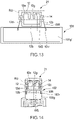
- FIG. 13 is a plan view showing a split-ring resonator according to an aspect of the present disclosure.
- FIG. 14 is a perspective view showing a split-ring resonator according to an aspect of the present disclosure.
- FIG. 15 is a view for comparing currents in split-ring resonators according to an aspect of the present disclosure.
- FIG. 16 is a plan view showing a split-ring resonator according to an aspect of the present disclosure.
- FIG. 17 is a plan view showing a split-ring resonator according to an aspect of the present disclosure.
- FIG. 18 is a perspective view showing a split-ring resonator according to an aspect of the present disclosure.
- FIG. 19 is a graph showing return loss properties of split-ring resonators according to an aspect of the present disclosure.
- FIG. 20 is a plan view showing a split-ring resonator according to an aspect of the present disclosure.
- FIG. 21 is a plan view showing a split-ring resonator according to an aspect of the present disclosure.
- FIG. 22 is a perspective view showing a split-ring resonator according to an aspect of the present disclosure.
- FIG. 23 is a view for comparing currents in split-ring resonators according to an aspect of the present disclosure.
- FIG. 24 is a graph showing return loss properties of split-ring resonators according to an aspect of the present disclosure.
- FIG. 25 is a plan view showing a split-ring resonator according to an aspect of the present disclosure.
- FIG. 26 is a plan view showing a split-ring resonator according to an aspect of the present disclosure.
- FIG. 27 is a perspective view showing a split-ring resonator according to an aspect of the present disclosure.
- FIG. 28 is a view for comparing connection configurations each of which is between a split-ring resonator and a board according to an aspect of the present disclosure.
- FIG. 29 is a view for comparing connection configurations each of which is between a split-ring resonator and a connector according to an aspect of the present disclosure.
- FIG. 30 is a plan view showing a split-ring resonator according to an aspect of the present disclosure.
- FIG. 31 is a plan view showing a split-ring resonator according to an aspect of the present disclosure.
- FIG. 32 is a perspective view showing a split-ring resonator according to an aspect of the present disclosure.
- FIG. 33 is a view for explaining about currents in radiating conductors.
- FIG. 34 is a plan view showing a split-ring resonator according to an aspect of the present disclosure.
- FIG. 35 is a plan view showing a split-ring resonator according to an aspect of the present disclosure.
- FIG. 36 is a perspective view showing a split-ring resonator according to an aspect of the present disclosure.
- FIG. 37 is a view for comparing connection configurations each of which is between a split-ring resonator and a board according to an aspect of the present disclosure.
- FIG. 38 is a plan view showing a split-ring resonator according to an aspect of the present disclosure.
- FIG. 39 is a plan view showing a split-ring resonator according to an aspect of the present disclosure.
- FIG. 40 is a perspective view showing a split-ring resonator according to an aspect of the present disclosure.
- FIG. 41 is a plan view showing a split-ring resonator according to an aspect of the present disclosure.
- FIG. 42 is a plan view showing a split-ring resonator according to an aspect of the present disclosure.
- FIG. 43 is a perspective view showing a split-ring resonator according to an aspect of the present disclosure.
- FIG. 44 is a plan view showing currents in radiating conductors according to an aspect of the present disclosure.
- FIG. 45 is a perspective view showing an example configuration for connecting a split-ring resonator according to an embodiment to a board via a lead.
- FIG. 46 is a perspective view showing another example configuration for connecting a split-ring resonator according to an embodiment to a board via a lead.
- FIG. 47 is a perspective view showing still another example configuration for connecting a split-ring resonator according to an embodiment to a board via a lead.
- FIG. 48 is a perspective view showing yet another example configuration for connecting a split-ring resonator according to an embodiment to a board via a lead.
- FIG. 49 is a perspective view showing further example configuration for connecting a split-ring resonator according to an embodiment to a board via a lead.
- FIG. 50 is a perspective view showing still further example configuration for connecting a split-ring resonator according to an embodiment to a board via a lead.
- FIG. 51 is a perspective view showing yet further example configuration for connecting a split-ring resonator according to an embodiment to a board via a lead.
- FIG. 52 is a perspective view showing yet further example configuration for connecting a split-ring resonator according to an embodiment to a board via a lead.
- FIG. 53 is a perspective view showing yet further example configuration for connecting a split-ring resonator according to an embodiment to a board via a lead.
- FIG. 54 is a perspective view showing yet further example configuration for connecting a split-ring resonator according to an embodiment to a board via a lead.
- FIG. 55 is a perspective view showing yet further example configuration for connecting a split-ring resonator according to an embodiment to a board via a lead.
- FIG. 56 is a perspective view showing yet further example configuration for connecting a split-ring resonator according to an embodiment to a board via a lead.
- FIG. 57 is a perspective view showing yet further example configuration for connecting a split-ring resonator according to an embodiment to a board via a lead.
- FIG. 58 is a perspective view showing yet further example configuration for connecting a split-ring resonator according to an embodiment to a board via a lead.
- a split-ring resonator 11 according to an aspect of the present disclosure comprises a ground terminal 14 which is separated from a ground pattern.
- FIGS. 1 , 2 and 3 are figures showing examples of the split-ring resonator 11 according to an aspect of the present disclosure.
- a center of a ring of the split-ring resonator 11 will be referred to as a point C.
- a line segment which connects a split of the split-ring resonator 11 and the point C to each other will be referred to as a line segment m.
- a straight-line which includes the line segment m will be referred to as a straight-line M.
- another straight-line which is perpendicular to the line segment m (or the straight-line M) and passes through the point C will be referred to as a straight-line L.
- the point C exists on the straight-line L.
- a direction in which the straight-line M extends will be referred to as the Y-axis direction.
- a direction in which the straight-line L extends will be referred to as the X-axis direction.
- the split-ring resonator 11 may comprise a split-ring 12 .
- the split-ring 12 may be shaped into a C-like shape extending along a rectangular ring, the C-like shape being formed of: a split portion 12 g ; a first conductor 12 a which extends in the X-axis direction while sandwiching the split portion 12 g therebetween; a second conductor 12 b which extends in the X-axis direction; a third conductor 12 c which extends in the Y-axis direction; and a fourth conductor 12 d which extends in the Y-axis direction.
- the split-ring 12 may have a shape which extends along one of various rings including a circular ring, an elliptical ring, a track-shaped ring and any other rings.
- the split-ring 12 may be formed of a metal plate.
- the split-ring resonator 11 may comprise the ground terminal 14 separated from a ground pattern.
- the split-ring resonator 11 may comprise not only the ground terminal 14 but also a plurality of the ground terminals 14 each separated from a ground pattern.
- the ground terminal 14 may have any structure, provided that the structure is electrically connectable with a ground pattern.
- the ground terminal 14 may be configured to be electrically connected with a ground pattern via soldering, pressure joining, a connector, a pin, etc.
- the ground terminal 14 may be a land pattern as shown in FIG. 1 .
- the ground terminal 14 may be a pattern which projects outward from the outer circumference of the split-ring resonator 11 as shown in FIG. 2 .
- the ground terminal 14 may be an exposed pattern which is formed by partially removing a coat of the split-ring resonator 11 as shown in FIG. 3 .
- the ground terminal 14 may have any structure, provided that the structure is electrically connectable with a ground pattern.
- the ground terminal 14 may be formed of a metal plate.
- FIGS. 4 , 5 and 6 are figures showing examples of the split-ring resonator 11 according to an aspect of the present disclosure.
- FIGS. 4 , 5 and 6 show a structure in which the split-ring resonator 11 comprises the one ground terminal 14 .
- the split-ring resonator 11 may comprise two or more of the ground terminals.
- the split-ring resonator 11 may comprise the split-ring 12 , the ground terminal 14 and a feeding terminal 13 .
- the feeding terminal 13 may be formed of a wire and a metal plate.
- the feeding terminal 13 may be a terminal for supplying radio frequency (RF) signals to the split-ring 12 .
- the feeding terminal 13 may be connected to the split-ring 12 .
- the feeding terminal 13 may be connected to a transmission line.
- the feeding terminal 13 may be connected to the first conductor 12 a.
- the split-ring resonator 11 may comprise the split-ring 12 , the ground terminal 14 , the feeding terminal 13 and a chip body 15 .
- the split-ring resonator 11 may comprise the split-ring 12 , the ground terminal 14 , the feeding terminal 13 and a printed circuit board 15 ′.
- the split-ring 12 , the ground terminal 14 and the feeding terminal 13 are provided on one of surfaces of the printed circuit board 15 ′.
- the printed circuit board 15 ′ may have either a single-layer structure or a multi-layer structure.
- the split-ring 12 , the ground terminal 14 and the feeding terminal 13 may be provided on one of layers thereof.
- a board according to an aspect of the present disclosure comprises a terminal configured to be connected to a ground terminal, which is separated from a ground pattern, of a split-ring resonator according to an aspect of the present disclosure.
- FIGS. 7 and 8 are figures showing examples of a board 101 according to an aspect of the present disclosure.
- the board 101 may comprise a ground pattern 101 g having a rectangular outline.
- the board 101 may comprise a reception terminal 101 r .
- the reception terminal 101 r may be a terminal configured to be connected to a ground terminal, which is separated from a ground pattern, of a split-ring resonator according to an aspect of the present disclosure.
- the board 101 may comprise an opening 101 a which corresponds to a shape and a size of a split-ring resonator according to an aspect of the present disclosure. In this case, for example, as shown in FIG.
- an antenna may be formed by accommodating a split-ring resonator according to an aspect of the present disclosure in the opening 101 a and by connecting the reception terminal 101 r to a ground terminal, which is separated from a ground pattern, of the split-ring resonator according to an aspect of the present disclosure.
- the board 101 may comprise no opening which corresponds to a shape and a size of a split-ring resonator according to an aspect of the present disclosure. In this case, for example, as shown in FIG.
- an antenna may be formed by arranging a split-ring resonator according to an aspect of the present disclosure to be adjacent to a side or an edge of a ground pattern 101 g ′ and by connecting the reception terminal 101 r to a ground terminal, which is separated from a ground pattern, of the split-ring resonator according to an aspect of the present disclosure.
- a connector according to an aspect of the present disclosure comprises a terminal configured to be connected to a ground terminal, which is separated from a ground pattern, of a split-ring resonator according to an aspect of the present disclosure.
- FIGS. 9 and 10 are figures showing examples of a connector 102 according to an aspect of the present disclosure.
- the connector 102 may comprise a ground pattern 102 g .
- the connector 102 may comprise a reception terminal 102 r .
- the connector 102 may comprise a feeding pattern 102 s .
- the connector 102 may be shaped in a cylindrical shape whose axial direction is an extending direction of the feeding pattern 102 s , and whose circumference surface is formed of the ground pattern 102 g , so that the connector 102 may be formed as a coaxial connector having a central wire of the connector formed of the feeding pattern 102 s and having an outer conductor of the connector formed of the ground pattern 102 g.
- the ground pattern 102 g may have a screw shape which is located at one of opposite ends of the connector 102 in the axial direction and may be electrically and mechanically connectable with another ground pattern having a corresponding screw shape.
- the connector 102 may comprise a dielectric cap 102 c which is located at a remaining one of the opposite ends in the axial direction and is adjacent to the ground pattern 102 g , so that the split-ring resonator 11 may be accommodatable in the dielectric cap 102 c .
- the split-ring resonator 11 may be provided at the remaining one of the opposite ends of the connector 102 in the axial direction to be adjacent to the ground pattern 102 g .
- the ground pattern 102 g may be connected to the ground terminal 14 via the reception terminal 102 r , and the feeding pattern 102 s may be connected to the feeding terminal 13 .
- the connector 102 may be a female connector with the ground pattern 102 g having a female screw shape.
- the connector 102 may be connected to a main circuit board 103 having a male connector.
- the split-ring resonator 11 (ground terminal 14 ) may be connected to a main ground pattern 103 g of the main circuit board 103 via the ground pattern 102 g .
- the ground pattern 102 g may have either a female screw shape or a male screw shape.
- the ground pattern 102 g of the connector 102 may have a male screw shape, and the connector 102 may be connected to a main circuit board having a female connector.
- a current in accordance with RF signals can flow between the feeding terminal 13 and the ground terminal 14 of a split-ring resonator 21 . Therefore, an antenna can be formed by combining the aforementioned split-ring resonator according to an aspect of the present disclosure to the aforementioned board according to an aspect of the present disclosure or the aforementioned connector according to an aspect of the present disclosure. Therefore, according to an aspect of the present disclosure described above, a split-ring resonator can be distributed as a single component and can be flexibly combined with the other component in accordance with design requirements.
- the split-ring resonator 21 is based on the split-ring resonator 11 while a first ground terminal is located on a section where a split of the split-ring resonator exists as viewed from the straight-line L.
- the point C exists, the point C being a center of a ring of the split-ring resonator.
- the straight-line L is perpendicular to the line segment m which connects the point C and the split to each other.
- FIGS. 11 , 12 , 13 and 14 are figures showing examples of the split-ring resonator 21 according to an aspect of the present disclosure.
- each section of a split-ring resonator will be defined as follows.
- a section where a split of a split-ring resonator is as viewed from the straight-line L is defined as an upper section RU of the split-ring resonator.
- an upper half part of the split-ring 12 i.e. a part formed of: the split portion 12 g ; the first conductor 12 a ; a part of the third conductor 12 c which is nearer to the first conductor 12 a than to the second conductor 12 b ; and a part of the fourth conductor 12 d which is nearer to the first conductor 12 a than to the second conductor 12 b
- the upper section RU of the split-ring resonator may be configured to be the upper section RU of the split-ring resonator.
- a section opposite to the section for the split of the split-ring resonator across the straight-line L is defined as a lower section RD of the split-ring resonator.
- a lower half part of the split-ring 12 i.e. a part formed of: the second conductor 12 b ; a part of the third conductor 12 c which is nearer to the second conductor 12 b than to the first conductor 12 a ; and a part of the fourth conductor 12 d which is nearer to the second conductor 12 b than to the first conductor 12 a
- one of opposite sections of the split-ring resonator across the straight-line M (the right section in FIG. 9 ) is defined as a right section RR.
- a right half part of the split-ring 12 i.e.
- a part formed of: the third conductor 12 c ; a part of the first conductor 12 a which is nearer to the third conductor 12 c than to the fourth conductor 12 d ; a part of the split portion 12 g which is nearer to the third conductor 12 c than to the fourth conductor 12 d ; and a part of the second conductor 12 b which is nearer to the third conductor 12 c than to the fourth conductor 12 d ) may be configured to be the right section RR of the split-ring resonator.
- a remaining one of the opposite sections across the straight-line M is defined as a left section RL.
- a left half part of the split-ring 12 i.e. a part formed of: the fourth conductor 12 d ; a part of the first conductor 12 a which is nearer to the fourth conductor 12 d than to the third conductor 12 c ; a part of the split portion 12 g which is nearer to the fourth conductor 12 d than to the third conductor 12 c ; and a part of the second conductor 12 b which is nearer to the fourth conductor 12 d than to the third conductor 12 c ) may be configured to be the left section RL of the split-ring resonator.
- the split-ring resonator 21 may comprise the ground terminal 14 located on the upper section RU of the split-ring resonator 21 .
- a position of each conductor of the third conductor 12 c and the fourth conductor 12 d may be provided with one of the ground terminals 14 , respectively.
- each ground terminal 14 may be connected to each conductor of the third conductor 12 c and the fourth conductor 12 d , respectively.
- the split-ring resonator 21 may be provided at a position of the opening 101 a of the board 101 .
- the split-ring resonator 21 may be provided in the opening 101 a so that a separation direction of the split portion 12 g is directed to a direction along which the opening 101 a is widen.
- the split-ring resonator 21 may be provided to the board 101 so that the split-ring resonator 21 is accommodated within the opening 101 a .
- the direction along which the opening 101 a is widen is defined as a direction along which one of the sides of the rectangular shape of the ground pattern 101 g extends, the one of the sides having a rectangular-shaped cut.
- each ground terminal 14 may be electrically connected with the ground pattern 101 g via soldering, pressure joining, etc.
- each ground terminal 14 may be connected to the ground pattern 101 g via solder SR.
- the first conductor 12 a may be connected to a feeding wire WS which supplies RF signals.
- a position of each conductor of the third conductor 12 c and the fourth conductor 12 d may be provided at any position in the upper section RU of the split-ring resonator 21 .
- the ground terminal 14 may be provided at a position of the first conductor 12 a .
- the ground terminal 14 may be connected to the first conductor 12 a .
- it may be connected to the third conductor 12 c or the fourth conductor 12 d at a position which is nearer to the split portion 12 g than to the ground terminal 14 .
- the feeding wire WS may be connected to the split portion 12 g.
- a board according to an aspect of the present disclosure comprises a terminal configured to be connected to the ground terminal, which is separated from a ground pattern, of the split-ring resonator 21 according to an aspect of the present disclosure.
- FIGS. 12 and 13 are figures showing examples of the board 101 according to an aspect of the present disclosure.
- the split-ring resonator 21 may comprise the ground terminal 14 located on the upper section RU of the split-ring resonator 21 .
- a position of each conductor of the third conductor 12 c and the fourth conductor 12 d is provided with one of the ground terminals 14 , respectively.
- Each ground terminal 14 may be connected to each conductor of the third conductor 12 c and the fourth conductor 12 d , respectively.
- the split-ring resonator 21 may be provided adjacent to an edge of the board 101 .
- the split-ring resonator 21 may be provided so that the separation direction of the split portion 12 g is aligned with a direction along which the adjacent edge of the board 101 extends.
- each ground terminal 14 may be electrically connected with the ground pattern 101 g ′ via a wire WR by soldering, pressure joining, etc.
- the feeding wire WS and the wire WR may be realized by a central wire and an outer conductor of a connector.
- the ground terminal 14 may be provided at any position in the upper section RU of the split-ring resonator 21 .
- the ground terminal 14 may be provided at a position of the first conductor 12 a .
- the ground terminal 14 may be connected to the first conductor 12 a.
- a connector according to an aspect of the present disclosure comprises a terminal configured to be connected to the ground terminal, which is separated from a ground pattern, of the split-ring resonator 21 according to an aspect of the present disclosure.
- FIG. 14 is a figure showing an example of the connector 102 according to an aspect of the present disclosure.
- the split-ring resonator 21 comprises the ground terminal 14 located on the upper section RU of the split-ring resonator 21 .
- a position of each conductor of the third conductor 12 c and the fourth conductor 12 d may be provided with one of the ground terminals 14 , respectively.
- each ground terminal 14 may be connected to each conductor of the third conductor 12 c and the fourth conductor 12 d , respectively.
- the split-ring resonator 21 may be provided to the connector 102 .
- the split-ring resonator 21 may be provided so that the separation direction of the split portion 12 g is aligned with the radial direction of the connector 102 .
- each ground terminal 14 may be electrically connected with the ground pattern 102 g via the wire WR by soldering, pressure joining, etc.
- the ground terminal 14 may be provided at any position in the upper section RU of the split-ring resonator 21 .
- the ground terminal 14 may be provided at a position of the first conductor 12 a .
- the ground terminal 14 may be connected to the first conductor 12 a.
- the connection is made so that the split-ring resonator is accommodated within the opening. Accordingly, in the split-ring resonator 21 illustrated in FIG. 12 , the current Ir in the upper section of the split-ring resonator 21 can flow on a side of the ground pattern 101 g of the board 101 through the ground terminal 14 without changing its direction. Therefore, the radiation property of the split-ring resonator 21 can be further improved.
- a split-ring resonator 31 is based on the split-ring resonator 21 while comprising a second ground terminal which is separated from a ground pattern, and the first ground terminal is located at a first corner of the split-ring resonator 31 .
- the second ground terminal is located on a section where the split exists as viewed from the straight-line L and is located at a second corner of the split-ring resonator.
- FIGS. 16 , 17 and 18 are figures showing examples of the split-ring resonator 31 according to an aspect of the present disclosure.
- the split-ring resonator 31 may comprise the ground terminals 14 located at positions of two corners (two parts including the intersection of the first conductor 12 a and the third conductor 12 c , and the intersection of the first conductor 12 a and the fourth conductor 12 d ) of the upper section RU of the split-ring resonator 31 , respectively.
- a board according to an aspect of the present disclosure comprises a terminal configured to be connected to the ground terminal, which is separated from a ground pattern, of the split-ring resonator 31 according to an aspect of the present disclosure.
- FIGS. 16 and 17 are figures showing examples of the board 101 according to an aspect of the present disclosure.
- the split-ring resonator 31 may comprise the ground terminals 14 located at the positions of the two corners (each of the intersection of the first conductor 12 a and the third conductor 12 c and the intersection of the first conductor 12 a and the fourth conductor 12 d ) of the upper section RU of the split-ring resonator 31 , respectively.
- a connector according to an aspect of the present disclosure comprises a terminal configured to be connected to the ground terminal, which is separated from a ground pattern, of the split-ring resonator 31 according to an aspect of the present disclosure.
- FIG. 18 is a figure showing an example of the connector 102 according to an aspect of the present disclosure.
- the split-ring resonator 31 may comprise the ground terminals 14 located at the positions of the two corners (each of the intersection of the first conductor 12 a and the third conductor 12 c and the intersection of the first conductor 12 a and the fourth conductor 12 d ) of the upper section RU of the split-ring resonator 31 , respectively.
- the ground terminals 14 are located on the two corners of the upper section RU of the split-ring resonator 31 .
- the current Ir further easily flows along a side in comparison with the split-ring resonator 21 illustrated in FIGS. 12 , 13 and 14 .
- the radiation property of the split-ring resonator 31 can be further improved.
- FIG. 19 shows frequency characteristics of return loss of each split-ring resonator under the same condition.
- the curve a shows a return loss curve of the split-ring resonator 31 illustrated in FIG. 15 .
- the curve b shows a return loss curve of the split-ring resonator 21 illustrated in FIG. 12 .
- the curve c shows a return loss curve of a split-ring resonator 51 according to a seventh embodiment lately illustrated in FIG. 21 .
- the curve d is a return loss curve of a reference example of a split-ring resonator which is based on a split-ring resonator 41 described later, and in which the ground terminal 14 is not provided while only a ground terminal 44 is provided. As shown in FIG.
- return losses at resonance frequency f 0 decrease in the order of the curve d, the curve c, the curve b and the curve a.
- the return loss property of the curve a is closest to the return loss property in a case where a split-ring resonator is integrally formed with a circuit board (in a case of an integral board).
- the split-ring resonator 41 is based on the split-ring resonator 21 or the split-ring resonator 31 while comprising a third ground terminal which is separated from a ground pattern, and the third ground terminal is located on a section where the split does not exist as viewed from the straight-line L.
- FIGS. 20 , 21 and 22 are figures showing examples of the split-ring resonator 41 according to an aspect of the present disclosure.
- the split-ring resonator 41 comprises the ground terminals 14 located on the upper section RU of the split-ring resonator 41 .
- a position of each conductor of the third conductor 12 c and the fourth conductor 12 d may be provided with one of the ground terminals 14 .
- the split-ring resonator 41 may further comprise the ground terminal 44 located on the lower section RD of the split-ring resonator 41 .
- the ground terminal 44 may be provided at a position of the second conductor 12 b .
- the ground terminal 44 may be connected to the second conductor 12 b .
- the ground terminal 44 may be connected to the ground pattern 101 g via the solder SR.
- a board according to an aspect of the present disclosure comprises a terminal configured to be connected to the ground terminal, which is separated from a ground pattern, of the split-ring resonator 41 according to an aspect of the present disclosure.
- FIGS. 20 and 21 are figures showing examples of the board 101 according to an aspect of the present disclosure.
- the split-ring resonator 41 may further comprise the ground terminal 44 located on the lower section RD of the split-ring resonator 41 .
- the ground terminal 44 may be provided at a position of the second conductor 12 b .
- the ground terminal 44 may be connected to the second conductor 12 b .
- the ground terminal 44 may be connected to the ground pattern 101 g via the solder SR.
- a connector according to an aspect of the present disclosure comprises a terminal configured to be connected to the ground terminal, which is separated from a ground pattern, of the split-ring resonator 41 according to an aspect of the present disclosure.
- FIG. 22 is a figure showing an example of the connector 102 according to an aspect of the present disclosure.
- the split-ring resonator 41 comprises the ground terminals 14 located on the upper section RU of the split-ring resonator 41 .
- a position of each conductor of the third conductor 12 c and the fourth conductor 12 d may be provided with one of the ground terminals 14 .
- the split-ring resonator 41 further comprises the ground terminal 44 located on the lower section RD of the split-ring resonator 41 .
- the ground terminal 44 may be provided at a position of the second conductor 12 b .
- the ground terminal 44 may be connected to the second conductor 12 b .
- the ground terminal 44 may be electrically connected with the ground pattern 101 g via the wire WR by soldering, pressure joining, etc.
- the ground terminal 44 may be applied to the split-ring resonator illustrated in FIG. 18 .
- the ground terminal 44 may be applied to the split-ring resonator illustrated in FIG. 14 .
- the ground terminal 44 for grounding of the feed current is provided on the lower section of the split-ring resonator 41 .
- a feeding point is located on a side of the upper section (on the first conductor 12 a including the split portion 12 g ), and that the feeding wire WS, which is connected to the feeding point, extends to the lower section of the split-ring resonator 41 through the opening located inside the ring of the split-ring resonator 41 .
- a return current Ig of a fed current Is is not diverted to the ground terminal 14 of the upper section but can flow from the split-ring resonator 41 directly to the ground pattern 101 g .
- the split-ring resonator 41 illustrated in FIG. 20 has less change in impedance and makes it easier to obtain matching in comparison with the split-ring resonator 21 illustrated in FIG. 12 . Therefore, as shown in FIG. 24 , the return loss at resonance frequency f 0 of the split-ring resonator 41 illustrated in FIG. 20 is small in comparison with the split-ring resonator 21 illustrated in FIG. 12 .
- the curve a′ and the curve b′ show frequency characteristics of return loss of the split-ring resonator 41 and the split-ring resonator 21 , respectively, under conditions different from those about FIG. 19 .
- the split-ring resonator 51 is based on the split-ring resonator 21 while a first ground terminal is located on a section where the split of the split-ring resonator does not exist as viewed from the straight-line L.
- the point C exists, the point C being a center of a ring of the split-ring resonator.
- the straight-line L is perpendicular to the line segment m which connects the point C and the split to each other (see FIG. 1 ).
- FIGS. 25 , 26 and 27 are figures showing examples of the split-ring resonator 51 according to an aspect of the present disclosure.
- the split-ring resonator 51 may comprise the ground terminal 14 located on the lower section RD of the split-ring resonator 51 .
- the ground terminals 14 may be provided at positions of two corners (each of the intersection of the second conductor 12 b and the third conductor 12 c and the intersection of the second conductor 12 b and the fourth conductor 12 d ) of the lower section RD of the split-ring resonator 51 , respectively.
- the ground terminals 14 are provided on the two corners of the lower section RD of the split-ring resonator 51 , respectively, they may be provided on any positions of the lower section RD of the split-ring resonator 51 .
- the ground terminals 14 may be provided at positions of the second conductor 12 b .
- the ground terminals 14 may be provided at a position of each conductor of the third conductor 12 c and the fourth conductor 12 d , respectively.
- a board according to an aspect of the present disclosure comprises a terminal configured to be connected to the ground terminal, which is separated from a ground pattern, of the split-ring resonator 51 according to an aspect of the present disclosure.
- FIGS. 25 and 26 are figures showing examples of the board 101 according to an aspect of the present disclosure.
- the split-ring resonator 51 may be provided adjacent to an edge of the board 101 .
- the split-ring resonator 51 may be provided so that the separation direction of the split portion 12 g is aligned with a direction along which the adjacent edge of the board 101 extends.
- a connector according to an aspect of the present disclosure comprises a terminal configured to be connected to the ground terminal, which is separated from a ground pattern, of the split-ring resonator 51 according to an aspect of the present disclosure.
- FIG. 27 is a figure showing an example of the connector 102 according to an aspect of the present disclosure.
- the split-ring resonator 51 is provided to the connector 102 to be adjacent to the ground pattern 102 g .
- the split-ring resonator 51 may be provided so that the separation direction of the split portion 12 g is aligned with the radial direction of the connector 102 .
- the ground terminals 14 may be connected to the ground pattern 102 g via the wires WR.
- the split portion 12 g is directed to a direction different from another direction along which the ground pattern 101 g ′ of the board 101 is located.
- the split-ring resonator 51 having the ground terminal 14 located on the lower section as illustrated in FIG. 26 can be connected to the ground pattern 101 g ′ by a distance shorter than that of the split-ring resonator 21 illustrated in FIG. 13 . Therefore, the split-ring resonator 51 illustrated in FIG. 26 is more easily connected to the board 101 than the split-ring resonator 21 illustrated in FIG. 13 because of its structure.
- the split portion 12 g is directed to a direction different from another direction along which the ground pattern 102 g of the connector 102 is located.
- the split-ring resonator 51 having the ground terminals located on the lower section as illustrated in FIG. 27 can be connected to the ground pattern 102 g by a distance shorter than that of the split-ring resonator 21 illustrated in FIG. 14 . Therefore, the split-ring resonator 51 illustrated in FIG. 27 is more easily connected to the connector 102 than the split-ring resonator 21 illustrated in FIG. 14 because of its structure.
- a split-ring resonator 61 is based on the split-ring resonator 51 while comprising a radiation conductor.
- FIGS. 30 , 31 and 32 are figures showing examples of the split-ring resonator 61 according to an aspect of the present disclosure.
- the split-ring resonator 61 may comprise radiation conductors 16 .
- the split-ring resonator 61 may comprise a pair of radiation conductors 16 (a radiation conductor 16 R and a radiation conductor 16 L) which are apart from each other and face each other in the separation direction of the split portion 12 g .
- the radiation conductor 16 R and the radiation conductor 16 L may extend so as to be away from each other in the separation direction.
- each of the radiation conductor 16 R and radiation conductor 16 L may be formed of a metal plate having a plate-like shape extending in the separation direction.
- the radiation conductors 16 may be provided on the upper section RU of the split-ring resonator 61 .
- the radiation conductor 16 R may be connected to the third conductor 12 c .
- the radiation conductor 16 L may be connected to the fourth conductor 12 d .
- an end of each of the radiation conductor 16 R and the radiation conductor 16 L, which is connected to the split-ring 12 may further extend in a direction intersecting with a plane in which the ground pattern 101 g extends so that the radiation conductor 16 R and the radiation conductor 16 L are not brought into contact with the ground pattern 101 g.
- a board according to an aspect of the present disclosure comprises a terminal configured to be connected to the ground terminal, which is separated from a ground pattern, of the split-ring resonator 61 according to an aspect of the present disclosure.
- FIGS. 30 and 31 are figures showing examples of the board 101 according to an aspect of the present disclosure.
- the split-ring resonator 61 may be provided adjacent to an edge of the board 101 .
- the split-ring resonator 61 may be provided so that the separation direction of the split portion 12 g is aligned with a direction along which the adjacent edge of the board 101 extends.
- a connector according to an aspect of the present disclosure comprises a terminal configured to be connected to the ground terminal, which is separated from a ground pattern, of the split-ring resonator 61 according to an aspect of the present disclosure.
- FIG. 32 is a figure showing an example of the connector 102 according to an aspect of the present disclosure.
- the split-ring resonator 61 may be provided to the connector 102 to be adjacent to the ground pattern 102 g .
- the split-ring resonator 61 may be provided so that the separation direction of the split portion 12 g is aligned with the radial direction of the connector 102 .
- the ground terminals 14 may be connected to the ground pattern 102 g via the wires WR.
- the current Ir which contributes for radiation tends to flow in the separation direction of the split portion 12 g . Accordingly, as shown in the lower left of FIG. 33 , since the split-ring resonator 61 illustrated in FIG. 30 comprises the radiation conductors 16 extending in the separation direction, the current Ir flows onto the radiation conductors 16 . Therefore, the split-ring resonator 61 illustrated in FIG. 30 has an improved radiation property in comparison with the split-ring resonator 51 illustrated in FIG. 25 . Moreover, for example, as shown in the lower right of FIG.
- the split-ring resonator 61 may comprise L-like shaped radiation conductors 17 as radiation conductors, the radiation conductor 17 extending in the separation direction to an end and then extending from the end in a direction intersecting with the separation direction along a plane in which the split-ring resonator 61 extends.
- the comparison of the split-ring resonator 61 illustrated in FIG. 31 with the split-ring resonator 51 illustrated in FIG. 26 comes to a similar conclusion.
- the comparison of the split-ring resonator 61 illustrated in FIG. 32 with the split-ring resonator 51 illustrated in FIG. 27 comes to a similar conclusion.
- a split-ring resonator 71 is based on the split-ring resonator 21 while all ground terminals including the previously described first ground terminal are located on one of opposite sections across the straight-line M.
- the straight-line M is a straight-line including a line segment which connects the point C and the split of the split-ring resonator to each other, the point C being a center of a ring of the split-ring resonator (see FIG. 1 ).
- FIGS. 34 , 35 and 36 are figures showing examples of the split-ring resonator 71 according to an aspect of the present disclosure.
- the split-ring resonator 71 may comprise the ground terminal 14 located either on the right section RR or on the left section RL of the split-ring resonator 71 .
- the ground terminal 14 may be provided on the right section RR of the split-ring resonator 71 .
- the ground terminal 14 may be provided at a position of the third conductor 12 c .
- the ground terminal 14 may be connected to the third conductor 12 c .
- the split-ring resonator 71 is provided to the opening 101 a so that the separation direction of the split portion 12 g intersects with the direction along which the opening 101 a is widen.
- the ground terminal 14 may be located in the opening 101 a and may be connected to an edge of the ground pattern 101 g which extends in the direction along which the opening 101 a is widen.
- the ground terminal 14 may be provided on the third conductor 12 c , it may be provided at any position of either the right section RR or the left section RL of the split-ring resonator 71 .
- the ground terminal 14 may be provided at a position of the first conductor 12 a .
- the ground terminal 14 may be connected to the first conductor 12 a .
- the ground terminal 14 may be provided at a position of the second conductor 12 b . In this case, the ground terminal 14 may be connected to the second conductor 12 b.
- a board according to an aspect of the present disclosure comprises a terminal configured to be connected to the ground terminal, which is separated from a ground pattern, of the split-ring resonator 71 according to an aspect of the present disclosure.
- FIGS. 34 and 35 are figures showing examples of the board 101 according to an aspect of the present disclosure.
- the split-ring resonator 71 may be provided adjacent to an edge of the board 101 .
- the split-ring resonator 71 may be provided so that a cutting direction of the split portion 12 g is aligned with a direction along which the adjacent edge of the board 101 extends.
- a connector according to an aspect of the present disclosure comprises a terminal configured to be connected to the ground terminal, which is separated from a ground pattern, of the split-ring resonator 71 according to an aspect of the present disclosure.
- FIG. 36 is a figure showing an example of the connector 102 according to an aspect of the present disclosure.
- the split-ring resonator 71 may be provided to the connector 102 to be adjacent to the ground pattern 102 g .
- the split-ring resonator 71 may be provided so that the cutting direction of the split portion 12 g is aligned with the radial direction of the connector 102 .
- the ground terminal 14 may be connected to the ground pattern 102 g via the wire WR.
- the split-ring resonator 71 illustrated in FIG. 34 can be easily connected to the ground pattern 101 g ′ when the ground terminal 14 is provided on either the right section RR or the left section RL of the split-ring resonator 71 .
- the connection is made easier in a case where the ground terminal 14 is provided on the right section RR of the split-ring resonator 71 in comparison with another case where the ground terminal 14 is provided on the left section RL (a comparative example illustrated in the left of FIG. 37 ).
- a split-ring resonator 81 is based on the split-ring resonator 71 while the first ground terminal is located on a section where the split exists as viewed from the straight-line L. On the straight-line L, the point C exists, and the straight-line L is perpendicular to the line segment m which connects the point C and the split to each other.
- FIGS. 38 , 39 and 40 are figures showing examples of the split-ring resonator 81 according to an aspect of the present disclosure.
- the split-ring resonator 81 may comprise the ground terminal 14 located on either the right section RR or the left section RL of the split-ring resonator 81 , for example, on the right section RR of the split-ring resonator 81 .
- the ground terminal 14 may be provided on the right section RR of the split-ring resonator 81 and on the upper section RU of the split-ring resonator 81 .
- a board according to an aspect of the present disclosure comprises a terminal configured to be connected to the ground terminal, which is separated from a ground pattern, of the split-ring resonator 81 according to an aspect of the present disclosure.
- FIGS. 38 and 39 are figures showing examples of the board 101 according to an aspect of the present disclosure.
- the split-ring resonator 81 may be provided adjacent to an edge of the board 101 .
- the split-ring resonator 81 may be provided so that the cutting direction of the split portion 12 g is aligned with a direction along which the adjacent edge of the board 101 extends.
- a connector according to an aspect of the present disclosure comprises a terminal configured to be connected to the ground terminal, which is separated from a ground pattern, of the split-ring resonator 81 according to an aspect of the present disclosure.
- FIG. 40 is a figure showing an example of the connector 102 according to an aspect of the present disclosure.
- the split-ring resonator 81 may be provided to the connector 102 to be adjacent to the ground pattern 102 g .
- the split-ring resonator 81 may be provided so that the cutting direction of the split portion 12 g is aligned with the radial direction of the connector 102 .
- the ground terminal 14 may be connected to the ground pattern 102 g via the wire WR.
- the comparison of the split-ring resonator 81 illustrated in FIG. 39 with the split-ring resonator 71 illustrated in FIG. 35 comes to a similar conclusion. Also, the comparison of the split-ring resonator 81 illustrated in FIG. 40 with the split-ring resonator 71 illustrated in FIG. 36 comes to a similar conclusion.
- a split-ring resonator 91 is based on the split-ring resonator 71 or the split-ring resonator 81 while comprising a radiation conductor located on a section where the first conductor does not exist as viewed from the straight-line M.
- FIGS. 41 , 42 and 43 are figures showing examples of the split-ring resonator 91 according to an aspect of the present disclosure.
- the split-ring resonator 91 may comprise a radiation conductor 16 ′.
- the split-ring resonator 91 may comprise the radiation conductor 16 ′ located on one of the right section RR and the left section RL of the split-ring resonator 91 , the one of the right section RR and the left section RL being located opposite to a remaining one where the ground terminal 14 is provided.
- the split-ring resonator 91 may comprise the radiation conductor 16 ′ located on the left section RL of the split-ring resonator 91 and located on the upper section RU of the split-ring resonator 91 .
- the radiation conductor 16 ′ may be connected to the fourth conductor 12 d .
- the radiation conductor 16 ′ may extend in the separation direction from an end connected to the split-ring 12 so as to be away from the fourth conductor 12 d .
- the radiation conductor 16 ′ may be formed of a metal plate having a plate-like shape extending from the split-ring 12 in the separation direction.
- the ground terminal 14 may be provided at any position of either the right section RR or the left section RL of the split-ring resonator 91 .
- the ground terminal 14 may be provided on either the right section RR or the left section RL of the split-ring resonator 91 , for example, on the lower section RD of the split-ring resonator 91 .
- a board according to an aspect of the present disclosure comprises a terminal configured to be connected to the ground terminal, which is separated from a ground pattern, of the split-ring resonator 91 according to an aspect of the present disclosure.
- FIGS. 41 and 42 are figures showing examples of the board 101 according to an aspect of the present disclosure.
- the split-ring resonator 91 may be provided adjacent to an edge of the board 101 .
- the split-ring resonator 91 may be provided so that the cutting direction of the split portion 12 g is aligned with a direction along which the adjacent edge of the board 101 extends.
- a connector according to an aspect of the present disclosure comprises a terminal configured to be connected to the ground terminal, which is separated from a ground pattern, of the split-ring resonator 91 according to an aspect of the present disclosure.
- FIG. 43 is a figure showing an example of the connector 102 according to an aspect of the present disclosure.
- the split-ring resonator 91 may be provided to the connector 102 to be adjacent to the ground pattern 102 g .
- the split-ring resonator 91 may be provided so that the cutting direction of the split portion 12 g is aligned with the radial direction of the connector 102 .
- the ground terminal 14 may be connected to the ground pattern 102 g via the wire WR.
- the current Ir which contributes for radiation tends to flow in the separation direction of the split portion 12 g . Accordingly, as shown in the lower left of FIG. 44 , since the split-ring resonator 91 illustrated in FIG. 41 comprises the radiation conductor 16 ′ extending in the separation direction, the current Ir flows onto the radiation conductor 16 ′. Therefore, the split-ring resonator 91 illustrated in FIG. 41 has an improved radiation property in comparison with the split-ring resonator 81 illustrated in FIG. 38 . Moreover, as shown in the lower right of FIG.
- the split-ring resonator 91 may comprise an L-like shaped radiation conductor 17 ′ as a radiation conductor, the radiation conductor 17 ′ extending in the separation direction to an end and then extending from the end in a direction intersecting with the separation direction along a plane in which the split-ring resonator 91 extends.
- the comparison of the split-ring resonator 91 illustrated in FIG. 42 with the split-ring resonator 81 illustrated in FIG. 39 comes to a similar conclusion.
- the comparison of the split-ring resonator 91 illustrated in FIG. 43 with the split-ring resonator 81 illustrated in FIG. 40 comes to a similar conclusion.
- the ground terminal 14 of the split-ring resonator may be connected by a lead 92 as shown in FIG. 45 .
- the ground terminal 14 of the split-ring resonator may be connected by the lead 92 as shown in FIG. 46 .
- the ground terminal 14 of the split-ring resonator may be connected by the lead 92 as shown in FIG. 47 .
- the ground terminal 14 of the split-ring resonator may be connected by the lead 92 as shown in FIG. 48 .
- the feeding wire WS of the split-ring resonator may be connected by a lead 93 .
- the ground terminal 14 of the split-ring resonator may be connected by the lead 92 .
- the feeding wire WS of the split-ring resonator may be connected by the lead 93 .
- the ground terminal 14 of the split-ring resonator may be connected by the lead 92 as shown in FIG. 50 .
- the ground terminal 14 and the feeding wire WS of the split-ring resonator may be connected by the lead 92 and the lead 93 , respectively.
- the ground terminal 14 of the split-ring resonator may be connected by the lead 92 so that the board 101 and the split-ring resonator have a gap G as shown in FIG. 52 .
- the ground terminal 14 of the split-ring resonator may be connected by the lead 92 so that the board 101 and the split-ring resonator have the gap G as shown in FIG. 53 .
- the ground terminal 14 of the split-ring resonator may be connected by the lead 92 so that the board 101 and the split-ring resonator have the gap G as shown in FIG. 54 .
- the ground terminal 14 and the feeding wire WS of the split-ring resonator may be connected by the lead 92 and the lead 93 , respectively, so that the board 101 and the split-ring resonator have the gap G.
- FIG. 55 the ground terminal 14 and the feeding wire WS of the split-ring resonator may be connected by the lead 92 and the lead 93 , respectively, so that the board 101 and the split-ring resonator have the gap G.
- the ground terminal 14 and the feeding wire WS of the split-ring resonator may be connected by the lead 92 and the lead 93 , respectively, so that the board 101 and the split-ring resonator.
- the ground terminal 14 of the split-ring resonator may be connected to the board 101 by the lead 92 as shown in FIG. 57 .
- the ground terminal 14 of the split-ring resonator may be connected to the board 101 the lead 92 as shown in FIG. 58 .
Landscapes
- Physics & Mathematics (AREA)
- Electromagnetism (AREA)
- Control Of Motors That Do Not Use Commutators (AREA)
- Piezo-Electric Or Mechanical Vibrators, Or Delay Or Filter Circuits (AREA)
- Coupling Device And Connection With Printed Circuit (AREA)
Abstract
Description
- Patent Document 1: WO 2013/027824
-
- 11 split-ring resonator
- 12 split-ring
- 12 a first conductor
- 12 b second conductor
- 12 c third conductor
- 12 d fourth conductor
- 12 g split portion
- 13 feeding terminal
- 14 ground terminal
- 15 chip body
- 15′ printed circuit board
- 16 radiation conductor
- 16′ radiation conductor
- 16L radiation conductor
- 16R radiation conductor
- 17 radiation conductor
- 17′ radiation conductor
- 21 split-ring resonator
- 31 split-ring resonator
- 41 split-ring resonator
- 44 ground terminal
- 51 split-ring resonator
- 61 split-ring resonator
- 71 split-ring resonator
- 81 split-ring resonator
- 91 split-ring resonator
- 92 lead
- 101 board
- 101 a opening
- 101 g ground pattern
- 101 g′ ground pattern
- 101 r reception terminal
- 102 connector
- 102 c dielectric cap
- 102 g ground pattern
- 102 s feeding pattern
- 102 r reception terminal
- 103 main circuit board
- 103 g main ground pattern
- 114 projecting pattern
- 214 exposed pattern
- C point
- f0 resonance frequency
- Ig return current
- Ir current
- Is fed current
- L straight-line
- M straight-line
- m line segment
- RD lower section
- RL left section
- RR right section
- RU upper section
- SR solder
- WR wire
- WS feeding wire
Claims (6)
Applications Claiming Priority (4)
| Application Number | Priority Date | Filing Date | Title |
|---|---|---|---|
| JPJP2018-077203 | 2018-04-12 | ||
| JP2018-077203 | 2018-04-12 | ||
| JP2018077203 | 2018-04-12 | ||
| PCT/JP2019/014785 WO2019198588A1 (en) | 2018-04-12 | 2019-04-03 | Split-ring resonator, baseplate, and connector |
Publications (2)
| Publication Number | Publication Date |
|---|---|
| US20210167505A1 US20210167505A1 (en) | 2021-06-03 |
| US11552399B2 true US11552399B2 (en) | 2023-01-10 |
Family
ID=68163170
Family Applications (1)
| Application Number | Title | Priority Date | Filing Date |
|---|---|---|---|
| US17/046,519 Active US11552399B2 (en) | 2018-04-12 | 2019-04-03 | Split-ring resonator, board and connector |
Country Status (7)
| Country | Link |
|---|---|
| US (1) | US11552399B2 (en) |
| EP (1) | EP3767749B1 (en) |
| JP (1) | JP7265532B2 (en) |
| KR (1) | KR102478925B1 (en) |
| CN (1) | CN112335124B (en) |
| TW (1) | TWI788553B (en) |
| WO (1) | WO2019198588A1 (en) |
Families Citing this family (4)
| Publication number | Priority date | Publication date | Assignee | Title |
|---|---|---|---|---|
| KR20210003260A (en) * | 2018-06-04 | 2021-01-11 | 니혼 고꾸 덴시 고교 가부시끼가이샤 | Split ring resonator and substrate |
| JP7475126B2 (en) * | 2019-10-29 | 2024-04-26 | 日本航空電子工業株式会社 | antenna |
| JP7608267B2 (en) * | 2021-05-19 | 2025-01-06 | 日本航空電子工業株式会社 | Multi-band Antennas |
| JP7764226B2 (en) | 2021-12-06 | 2025-11-05 | 日本航空電子工業株式会社 | Antenna device |
Citations (9)
| Publication number | Priority date | Publication date | Assignee | Title |
|---|---|---|---|---|
| US5055809A (en) * | 1988-08-04 | 1991-10-08 | Matsushita Electric Industrial Co., Ltd. | Resonator and a filter including the same |
| US5164690A (en) * | 1991-06-24 | 1992-11-17 | Motorola, Inc. | Multi-pole split ring resonator bandpass filter |
| US20030148784A1 (en) | 2001-06-05 | 2003-08-07 | Masatoshi Sawamura | Mobile wireless terminal |
| WO2013027824A1 (en) | 2011-08-24 | 2013-02-28 | 日本電気株式会社 | Antenna and electronic device |
| WO2015151430A1 (en) | 2014-03-31 | 2015-10-08 | 日本電気株式会社 | Antenna, array antenna and wireless communication device |
| JP2015179938A (en) | 2014-03-19 | 2015-10-08 | 学校法人智香寺学園 | Small-sized antenna |
| WO2015151139A1 (en) | 2014-03-31 | 2015-10-08 | 日本電気株式会社 | Antenna, antenna array, and wireless communication device |
| WO2016159369A1 (en) | 2015-04-02 | 2016-10-06 | 日本電気株式会社 | Multi-band antenna and radio communication device |
| US20180234072A1 (en) * | 2017-02-10 | 2018-08-16 | Arcadyan Technology Corporation | Split Ring Resonator Antenna |
Family Cites Families (10)
| Publication number | Priority date | Publication date | Assignee | Title |
|---|---|---|---|---|
| JPH0637519A (en) * | 1992-04-02 | 1994-02-10 | Matsushita Electric Ind Co Ltd | Resonator |
| JP4523478B2 (en) * | 2005-04-28 | 2010-08-11 | 京セラ株式会社 | Band-pass filter, high-frequency module, and wireless communication device using the same |
| WO2009013817A1 (en) * | 2007-07-25 | 2009-01-29 | Fujitsu Limited | Wireless tag |
| WO2009090815A1 (en) * | 2008-01-17 | 2009-07-23 | Murata Manufacturing Co., Ltd. | Strip-line filter |
| KR100962565B1 (en) | 2008-01-22 | 2010-06-22 | 주식회사 모비텍 | Broadband Planar Reverse Antenna |
| JP5920868B2 (en) | 2011-10-07 | 2016-05-18 | 国立大学法人電気通信大学 | Transmission line resonator, bandpass filter and duplexer |
| JP5863730B2 (en) * | 2013-08-27 | 2016-02-17 | Necプラットフォームズ株式会社 | ANTENNA DEVICE AND WIRELESS COMMUNICATION DEVICE |
| JP6240040B2 (en) | 2013-08-27 | 2017-11-29 | Necプラットフォームズ株式会社 | ANTENNA DEVICE AND WIRELESS COMMUNICATION DEVICE |
| JP6138839B2 (en) * | 2015-01-14 | 2017-05-31 | Necプラットフォームズ株式会社 | Antenna structure |
| JP2018077203A (en) | 2016-11-07 | 2018-05-17 | 有限会社円研工業 | Inner angle measuring tool |
-
2019
- 2019-04-03 WO PCT/JP2019/014785 patent/WO2019198588A1/en not_active Ceased
- 2019-04-03 CN CN201980024970.6A patent/CN112335124B/en active Active
- 2019-04-03 EP EP19785015.9A patent/EP3767749B1/en active Active
- 2019-04-03 US US17/046,519 patent/US11552399B2/en active Active
- 2019-04-03 JP JP2020513218A patent/JP7265532B2/en active Active
- 2019-04-03 KR KR1020207029052A patent/KR102478925B1/en active Active
- 2019-04-09 TW TW108112227A patent/TWI788553B/en active
Patent Citations (14)
| Publication number | Priority date | Publication date | Assignee | Title |
|---|---|---|---|---|
| US5055809A (en) * | 1988-08-04 | 1991-10-08 | Matsushita Electric Industrial Co., Ltd. | Resonator and a filter including the same |
| US5164690A (en) * | 1991-06-24 | 1992-11-17 | Motorola, Inc. | Multi-pole split ring resonator bandpass filter |
| US20030148784A1 (en) | 2001-06-05 | 2003-08-07 | Masatoshi Sawamura | Mobile wireless terminal |
| US20170040689A1 (en) | 2011-08-24 | 2017-02-09 | Nec Corporation | Antenna and electronic device |
| US20140203993A1 (en) | 2011-08-24 | 2014-07-24 | Nec Corporation | Antenna and electronic device |
| WO2013027824A1 (en) | 2011-08-24 | 2013-02-28 | 日本電気株式会社 | Antenna and electronic device |
| JP2015179938A (en) | 2014-03-19 | 2015-10-08 | 学校法人智香寺学園 | Small-sized antenna |
| WO2015151430A1 (en) | 2014-03-31 | 2015-10-08 | 日本電気株式会社 | Antenna, array antenna and wireless communication device |
| WO2015151139A1 (en) | 2014-03-31 | 2015-10-08 | 日本電気株式会社 | Antenna, antenna array, and wireless communication device |
| US20170117612A1 (en) | 2014-03-31 | 2017-04-27 | Nec Corporation | Antenna, array antenna, and radio communication apparatus |
| US10476132B2 (en) | 2014-03-31 | 2019-11-12 | Nec Corporation | Antenna, antenna array, and radio communication apparatus |
| WO2016159369A1 (en) | 2015-04-02 | 2016-10-06 | 日本電気株式会社 | Multi-band antenna and radio communication device |
| US20180090833A1 (en) | 2015-04-02 | 2018-03-29 | Nec Corporation | Multi-band antenna and radio communication device |
| US20180234072A1 (en) * | 2017-02-10 | 2018-08-16 | Arcadyan Technology Corporation | Split Ring Resonator Antenna |
Non-Patent Citations (8)
| Title |
|---|
| European Office Action dated Dec. 17, 2021, issued in counterpart European Application No. 19785015.9. |
| European Office Action dated Jul. 18, 2022, issued in counterpart European Application No. 19785015.9. |
| Extended European Search Report (EESR) dated Apr. 16, 2021 issued in counterpart European Application No. 19785015.9. |
| International Search Report (ISR) (and English translation thereof) dated Jun. 25, 2019 issued in International Application No. PCT/JP2019/014785. |
| Japanese Office Action (and English language translation thereof) dated Oct. 5, 2022, issued in counterpart Japanese Application No. 2020-513218. |
| Korean Office Action (and English language translation thereof) dated Sep. 13, 2021 issued in counterpart Korean Application No. 10-2020-7029052. |
| Taiwanese Office Action (and English language translation thereof) dated Jun. 30, 2022, issued in counterpart Taiwanese Application No. 108112227. |
| Written Opinion dated Jun. 25, 2019 issued in International Application No. PCT/JP2019/014785. |
Also Published As
| Publication number | Publication date |
|---|---|
| KR20200126425A (en) | 2020-11-06 |
| JPWO2019198588A1 (en) | 2021-04-15 |
| KR102478925B1 (en) | 2022-12-20 |
| EP3767749B1 (en) | 2024-02-14 |
| TW202005167A (en) | 2020-01-16 |
| TWI788553B (en) | 2023-01-01 |
| JP7265532B2 (en) | 2023-04-26 |
| WO2019198588A1 (en) | 2019-10-17 |
| US20210167505A1 (en) | 2021-06-03 |
| CN112335124B (en) | 2024-03-19 |
| EP3767749A1 (en) | 2021-01-20 |
| EP3767749A4 (en) | 2021-05-19 |
| CN112335124A (en) | 2021-02-05 |
Similar Documents
| Publication | Publication Date | Title |
|---|---|---|
| US11552399B2 (en) | Split-ring resonator, board and connector | |
| US10164384B2 (en) | Coaxial connector | |
| US10148027B2 (en) | Structure for connecting board and connector, board, and method for connecting board and connector | |
| US11223170B2 (en) | Surface mount connector and surface mount connector set | |
| US11862877B2 (en) | Antenna, board and communication device | |
| US11695221B2 (en) | Flexible polymer antenna with multiple ground resonators | |
| US10476132B2 (en) | Antenna, antenna array, and radio communication apparatus | |
| US11394108B2 (en) | Antenna device | |
| US20200295449A1 (en) | Antenna device | |
| EP1764865A1 (en) | Wide band biconical antennas with an integrated matching system | |
| US20210210831A1 (en) | Split-ring resonator and board | |
| US20230318186A1 (en) | Miniature antenna with omnidirectional radiation field | |
| CN104466329A (en) | Dielectric waveguide input/output structure and dielectric waveguide duplexer | |
| US20110221638A1 (en) | Internal lc antenna for wireless communication device | |
| US20180049313A1 (en) | Coupler for proximity wireless communication | |
| CN108604737A (en) | Antenna feeding network including coaxial connector | |
| US20090224986A1 (en) | Radio apparatus and antenna device having element formed on casing material | |
| US11843159B2 (en) | Split ring resonator and communication device | |
| US11978967B2 (en) | UWB antenna | |
| EP3203576A1 (en) | Planar printed antenna and system | |
| US20220359986A1 (en) | Antenna system with short cable | |
| CN117748124A (en) | Radiating element, antenna and base station | |
| JP2006237904A (en) | Patch antenna | |
| JP2009267765A (en) | Method of manufacturing on-vehicle integrated antenna |
Legal Events
| Date | Code | Title | Description |
|---|---|---|---|
| AS | Assignment |
Owner name: JAPAN AVIATION ELECTRONICS INDUSTRY, LIMITED, JAPAN Free format text: ASSIGNMENT OF ASSIGNORS INTEREST;ASSIGNORS:KOSAKA, KEISHI;HANKUI, EIJI;TOYAO, HIROSHI;AND OTHERS;REEL/FRAME:054018/0630 Effective date: 20200930 |
|
| FEPP | Fee payment procedure |
Free format text: ENTITY STATUS SET TO UNDISCOUNTED (ORIGINAL EVENT CODE: BIG.); ENTITY STATUS OF PATENT OWNER: LARGE ENTITY |
|
| STPP | Information on status: patent application and granting procedure in general |
Free format text: APPLICATION DISPATCHED FROM PREEXAM, NOT YET DOCKETED |
|
| STPP | Information on status: patent application and granting procedure in general |
Free format text: DOCKETED NEW CASE - READY FOR EXAMINATION |
|
| STPP | Information on status: patent application and granting procedure in general |
Free format text: NON FINAL ACTION MAILED |
|
| STPP | Information on status: patent application and granting procedure in general |
Free format text: RESPONSE TO NON-FINAL OFFICE ACTION ENTERED AND FORWARDED TO EXAMINER |
|
| STPP | Information on status: patent application and granting procedure in general |
Free format text: NON FINAL ACTION MAILED |
|
| STPP | Information on status: patent application and granting procedure in general |
Free format text: NOTICE OF ALLOWANCE MAILED -- APPLICATION RECEIVED IN OFFICE OF PUBLICATIONS |
|
| STPP | Information on status: patent application and granting procedure in general |
Free format text: NOTICE OF ALLOWANCE MAILED -- APPLICATION RECEIVED IN OFFICE OF PUBLICATIONS |
|
| STPP | Information on status: patent application and granting procedure in general |
Free format text: PUBLICATIONS -- ISSUE FEE PAYMENT RECEIVED |
|
| STPP | Information on status: patent application and granting procedure in general |
Free format text: PUBLICATIONS -- ISSUE FEE PAYMENT VERIFIED |
|
| STCF | Information on status: patent grant |
Free format text: PATENTED CASE |