US11552376B2 - Electrode assembly and method for manufacturing the same - Google Patents
Electrode assembly and method for manufacturing the same Download PDFInfo
- Publication number
- US11552376B2 US11552376B2 US16/646,273 US201916646273A US11552376B2 US 11552376 B2 US11552376 B2 US 11552376B2 US 201916646273 A US201916646273 A US 201916646273A US 11552376 B2 US11552376 B2 US 11552376B2
- Authority
- US
- United States
- Prior art keywords
- electrode
- positive
- negative
- electrodes
- bus bar
- Prior art date
- Legal status (The legal status is an assumption and is not a legal conclusion. Google has not performed a legal analysis and makes no representation as to the accuracy of the status listed.)
- Active, expires
Links
Images


Classifications
-
- H—ELECTRICITY
- H01—ELECTRIC ELEMENTS
- H01M—PROCESSES OR MEANS, e.g. BATTERIES, FOR THE DIRECT CONVERSION OF CHEMICAL ENERGY INTO ELECTRICAL ENERGY
- H01M10/00—Secondary cells; Manufacture thereof
- H01M10/05—Accumulators with non-aqueous electrolyte
- H01M10/058—Construction or manufacture
- H01M10/0585—Construction or manufacture of accumulators having only flat construction elements, i.e. flat positive electrodes, flat negative electrodes and flat separators
-
- H—ELECTRICITY
- H01—ELECTRIC ELEMENTS
- H01M—PROCESSES OR MEANS, e.g. BATTERIES, FOR THE DIRECT CONVERSION OF CHEMICAL ENERGY INTO ELECTRICAL ENERGY
- H01M10/00—Secondary cells; Manufacture thereof
- H01M10/04—Construction or manufacture in general
- H01M10/0436—Small-sized flat cells or batteries for portable equipment
-
- B—PERFORMING OPERATIONS; TRANSPORTING
- B23—MACHINE TOOLS; METAL-WORKING NOT OTHERWISE PROVIDED FOR
- B23K—SOLDERING OR UNSOLDERING; WELDING; CLADDING OR PLATING BY SOLDERING OR WELDING; CUTTING BY APPLYING HEAT LOCALLY, e.g. FLAME CUTTING; WORKING BY LASER BEAM
- B23K20/00—Non-electric welding by applying impact or other pressure, with or without the application of heat, e.g. cladding or plating
- B23K20/10—Non-electric welding by applying impact or other pressure, with or without the application of heat, e.g. cladding or plating making use of vibrations, e.g. ultrasonic welding
-
- H—ELECTRICITY
- H01—ELECTRIC ELEMENTS
- H01M—PROCESSES OR MEANS, e.g. BATTERIES, FOR THE DIRECT CONVERSION OF CHEMICAL ENERGY INTO ELECTRICAL ENERGY
- H01M10/00—Secondary cells; Manufacture thereof
- H01M10/04—Construction or manufacture in general
- H01M10/0413—Large-sized flat cells or batteries for motive or stationary systems with plate-like electrodes
-
- H—ELECTRICITY
- H01—ELECTRIC ELEMENTS
- H01M—PROCESSES OR MEANS, e.g. BATTERIES, FOR THE DIRECT CONVERSION OF CHEMICAL ENERGY INTO ELECTRICAL ENERGY
- H01M10/00—Secondary cells; Manufacture thereof
- H01M10/04—Construction or manufacture in general
- H01M10/0472—Vertically superposed cells with vertically disposed plates
-
- H—ELECTRICITY
- H01—ELECTRIC ELEMENTS
- H01M—PROCESSES OR MEANS, e.g. BATTERIES, FOR THE DIRECT CONVERSION OF CHEMICAL ENERGY INTO ELECTRICAL ENERGY
- H01M10/00—Secondary cells; Manufacture thereof
- H01M10/05—Accumulators with non-aqueous electrolyte
- H01M10/058—Construction or manufacture
- H01M10/0583—Construction or manufacture of accumulators with folded construction elements except wound ones, i.e. folded positive or negative electrodes or separators, e.g. with "Z"-shaped electrodes or separators
-
- H—ELECTRICITY
- H01—ELECTRIC ELEMENTS
- H01M—PROCESSES OR MEANS, e.g. BATTERIES, FOR THE DIRECT CONVERSION OF CHEMICAL ENERGY INTO ELECTRICAL ENERGY
- H01M50/00—Constructional details or processes of manufacture of the non-active parts of electrochemical cells other than fuel cells, e.g. hybrid cells
- H01M50/50—Current conducting connections for cells or batteries
- H01M50/502—Interconnectors for connecting terminals of adjacent batteries; Interconnectors for connecting cells outside a battery casing
-
- H—ELECTRICITY
- H01—ELECTRIC ELEMENTS
- H01M—PROCESSES OR MEANS, e.g. BATTERIES, FOR THE DIRECT CONVERSION OF CHEMICAL ENERGY INTO ELECTRICAL ENERGY
- H01M50/00—Constructional details or processes of manufacture of the non-active parts of electrochemical cells other than fuel cells, e.g. hybrid cells
- H01M50/50—Current conducting connections for cells or batteries
- H01M50/528—Fixed electrical connections, i.e. not intended for disconnection
- H01M50/529—Intercell connections through partitions, e.g. in a battery casing
-
- H—ELECTRICITY
- H01—ELECTRIC ELEMENTS
- H01M—PROCESSES OR MEANS, e.g. BATTERIES, FOR THE DIRECT CONVERSION OF CHEMICAL ENERGY INTO ELECTRICAL ENERGY
- H01M50/00—Constructional details or processes of manufacture of the non-active parts of electrochemical cells other than fuel cells, e.g. hybrid cells
- H01M50/50—Current conducting connections for cells or batteries
- H01M50/531—Electrode connections inside a battery casing
- H01M50/534—Electrode connections inside a battery casing characterised by the material of the leads or tabs
-
- H—ELECTRICITY
- H01—ELECTRIC ELEMENTS
- H01M—PROCESSES OR MEANS, e.g. BATTERIES, FOR THE DIRECT CONVERSION OF CHEMICAL ENERGY INTO ELECTRICAL ENERGY
- H01M50/00—Constructional details or processes of manufacture of the non-active parts of electrochemical cells other than fuel cells, e.g. hybrid cells
- H01M50/50—Current conducting connections for cells or batteries
- H01M50/531—Electrode connections inside a battery casing
- H01M50/54—Connection of several leads or tabs of plate-like electrode stacks, e.g. electrode pole straps or bridges
-
- H—ELECTRICITY
- H01—ELECTRIC ELEMENTS
- H01M—PROCESSES OR MEANS, e.g. BATTERIES, FOR THE DIRECT CONVERSION OF CHEMICAL ENERGY INTO ELECTRICAL ENERGY
- H01M50/00—Constructional details or processes of manufacture of the non-active parts of electrochemical cells other than fuel cells, e.g. hybrid cells
- H01M50/50—Current conducting connections for cells or batteries
- H01M50/543—Terminals
- H01M50/547—Terminals characterised by the disposition of the terminals on the cells
- H01M50/548—Terminals characterised by the disposition of the terminals on the cells on opposite sides of the cell
-
- H—ELECTRICITY
- H01—ELECTRIC ELEMENTS
- H01M—PROCESSES OR MEANS, e.g. BATTERIES, FOR THE DIRECT CONVERSION OF CHEMICAL ENERGY INTO ELECTRICAL ENERGY
- H01M50/00—Constructional details or processes of manufacture of the non-active parts of electrochemical cells other than fuel cells, e.g. hybrid cells
- H01M50/50—Current conducting connections for cells or batteries
- H01M50/543—Terminals
- H01M50/552—Terminals characterised by their shape
- H01M50/553—Terminals adapted for prismatic, pouch or rectangular cells
-
- H—ELECTRICITY
- H01—ELECTRIC ELEMENTS
- H01M—PROCESSES OR MEANS, e.g. BATTERIES, FOR THE DIRECT CONVERSION OF CHEMICAL ENERGY INTO ELECTRICAL ENERGY
- H01M50/00—Constructional details or processes of manufacture of the non-active parts of electrochemical cells other than fuel cells, e.g. hybrid cells
- H01M50/50—Current conducting connections for cells or batteries
- H01M50/543—Terminals
- H01M50/564—Terminals characterised by their manufacturing process
- H01M50/566—Terminals characterised by their manufacturing process by welding, soldering or brazing
-
- B—PERFORMING OPERATIONS; TRANSPORTING
- B23—MACHINE TOOLS; METAL-WORKING NOT OTHERWISE PROVIDED FOR
- B23K—SOLDERING OR UNSOLDERING; WELDING; CLADDING OR PLATING BY SOLDERING OR WELDING; CUTTING BY APPLYING HEAT LOCALLY, e.g. FLAME CUTTING; WORKING BY LASER BEAM
- B23K2101/00—Articles made by soldering, welding or cutting
- B23K2101/36—Electric or electronic devices
- B23K2101/38—Conductors
-
- H—ELECTRICITY
- H01—ELECTRIC ELEMENTS
- H01M—PROCESSES OR MEANS, e.g. BATTERIES, FOR THE DIRECT CONVERSION OF CHEMICAL ENERGY INTO ELECTRICAL ENERGY
- H01M50/00—Constructional details or processes of manufacture of the non-active parts of electrochemical cells other than fuel cells, e.g. hybrid cells
- H01M50/50—Current conducting connections for cells or batteries
- H01M50/531—Electrode connections inside a battery casing
- H01M50/536—Electrode connections inside a battery casing characterised by the method of fixing the leads to the electrodes, e.g. by welding
-
- Y—GENERAL TAGGING OF NEW TECHNOLOGICAL DEVELOPMENTS; GENERAL TAGGING OF CROSS-SECTIONAL TECHNOLOGIES SPANNING OVER SEVERAL SECTIONS OF THE IPC; TECHNICAL SUBJECTS COVERED BY FORMER USPC CROSS-REFERENCE ART COLLECTIONS [XRACs] AND DIGESTS
- Y02—TECHNOLOGIES OR APPLICATIONS FOR MITIGATION OR ADAPTATION AGAINST CLIMATE CHANGE
- Y02E—REDUCTION OF GREENHOUSE GAS [GHG] EMISSIONS, RELATED TO ENERGY GENERATION, TRANSMISSION OR DISTRIBUTION
- Y02E60/00—Enabling technologies; Technologies with a potential or indirect contribution to GHG emissions mitigation
- Y02E60/10—Energy storage using batteries
-
- Y—GENERAL TAGGING OF NEW TECHNOLOGICAL DEVELOPMENTS; GENERAL TAGGING OF CROSS-SECTIONAL TECHNOLOGIES SPANNING OVER SEVERAL SECTIONS OF THE IPC; TECHNICAL SUBJECTS COVERED BY FORMER USPC CROSS-REFERENCE ART COLLECTIONS [XRACs] AND DIGESTS
- Y02—TECHNOLOGIES OR APPLICATIONS FOR MITIGATION OR ADAPTATION AGAINST CLIMATE CHANGE
- Y02P—CLIMATE CHANGE MITIGATION TECHNOLOGIES IN THE PRODUCTION OR PROCESSING OF GOODS
- Y02P70/00—Climate change mitigation technologies in the production process for final industrial or consumer products
- Y02P70/50—Manufacturing or production processes characterised by the final manufactured product
Definitions
- the present invention relates to an electrode assembly and a method for manufacturing the same and, more particularly, to an electrode assembly, in which a deviation in current density inside a cell is reduced, and a method for manufacturing the same.
- Batteries (cells) that generate electric energy through physical or chemical reaction of materials to supply power to the outside are used when alternate current (AC) power to be supplied to the building is not obtained, or direct current (DC) power is required according to the living environments surrounded by various electrical/electronic devices.
- AC alternate current
- DC direct current
- primary batteries and secondary batteries which are chemical cells using chemical reaction
- the primary batteries are consumable cells which are collectively referred to as dry cells.
- the secondary batteries are rechargeable batteries manufactured by using a material in which oxidation and reduction processes between current and a material are capable of being repeated several times. That is, power is recharged when the reduction reaction to the material is performed by the current, power is discharged when the oxidation reaction to the material is performed. Such the recharging and discharging are repeatedly performed to generate electricity.
- a lithium ion battery among the secondary batteries is manufactured in such a manner in which: an active material is applied, with a predetermined thickness, to each of a positive electrode conductive foil and a negative electrode conductive foil; a separator is disposed between both the conductive foils so as to be wound several times in an approximate jelly roll or cylindrical shape and thereby to manufacture an electrode assembly; and the electrode assembly is accommodated in a cylindrical or prismatic can, a pouch, or the like to be sealed.
- lithium ion battery As such a lithium ion battery has been commercialized and widely used, applications thereof also become diverse in vehicles/electronic devices/power tools.
- an output of the secondary battery has also been regarded as an important specification.
- a positive electrode/a separator/a negative electrode/a separator are stacked sequentially and connected to a tab part, thereby establishing connection between the positive electrodes and between the negative electrodes.
- a battery cell having excellent structural safety and insulation resistance is disclosed in Korean Patent Publication No. 10-2008-0038465.
- one positive electrode terminal and one negative electrode terminal are being used in a single direction/bi-direction.
- Such a pouch battery according to the related art has a problem in which a size of a tab that is an inlet for electrons is small relative to a gradually increasing electrode area.
- an object of the present invention is to provide an electrode assembly capable of securing an electron transfer path inside the electrode assembly and a method for manufacturing the same.
- a single electrode assembly in which a plurality of negative electrodes and positive electrodes are stacked alternately and repeatedly, and separators are disposed between the plurality of negative electrodes and positive electrodes, according to an embodiment of the present invention includes: a negative electrode tab part formed on one end of the electrode assembly and extending from the plurality of negative electrodes; a positive electrode bus bar spaced apart from the negative electrode tab part on the one end of the electrode assembly and electrically connecting the plurality of the positive electrodes; a positive electrode tab part formed on the other end of the electrode assembly opposite to the one end and extending from the plurality of positive electrodes; and a negative electrode bus bar spaced apart from the positive electrode tab part on the other end of the electrode assembly and electrically connecting the plurality of the negative electrodes.
- the positive electrode bus bar and the negative electrode bus bar may be formed in symmetrical positions about a central portion of the electrode assembly.
- Each of the positive electrode bus bar and the negative electrode bus bar may be formed in plurality.
- the positive electrode bus bar may be formed as an electrode collector extending from the positive electrodes, and the negative electrode bus bar may be formed as an electrode collector extending from the negative electrodes.
- the single electrode assembly may include an insulating member installed either between the positive electrode bus bar and the negative electrodes of the electrode assembly so as to insulate the positive electrode bus bar from the negative electrodes or between the negative electrode bus bar and the positive electrodes of the electrode assembly so as to insulate the negative electrode bus bar from the positive electrodes.
- a method for manufacturing an electrode stack according to an embodiment of the present invention includes: a stacking step of alternately stacking electrodes and separators to form an electrode stack, wherein the electrode stack is formed by using negative electrodes including negative electrode extension parts that are portions longer than positive electrodes and separators on one end of the electrode stack and the positive electrodes including positive electrode extension parts that are portions longer than the negative electrodes and the separators on the other end of the electrode stack; a negative electrode welding step of welding the plurality of negative electrode extension parts included in the plurality of negative electrodes; and a positive electrode welding step of welding the plurality of positive electrode extension parts included in the plurality of positive electrodes.
- the positive electrodes in which a positive electrode tab part is formed on the one end, the separators, and the negative electrodes including the negative electrode extension parts on the one end may be stacked sequentially.
- portions spaced apart from the positive electrode tab part in the negative electrode extension parts may be welded.
- the negative electrodes in which a negative electrode tab part is formed on the other end, the separators, and the positive electrodes including the positive electrode extension parts on the other end may be stacked sequentially.
- portions spaced apart from the negative electrode tab part in the positive electrode extension parts may be welded.
- each of the negative electrode extension parts and the positive electrode extension parts may be welded through ultrasonic welding or thermal welding.
- the method may further include a negative electrode cutting step of cutting portions that are not welded to each other in the negative electrode extension parts.
- the negative electrode extension parts that are not cut but welded to each other in the negative electrode cutting step may provide a negative electrode bus bar.
- the method may further include a first insulating member installation step of installing an insulating member to insulate the negative electrode bus bar from the positive electrodes of the electrode stack.
- the method may further include a positive electrode cutting step of cutting portions that are not welded to each other in the positive electrode extension parts.
- the positive electrode extension parts that are not cut but welded to each other in the positive electrode cutting step may provide a positive electrode bus bar.
- the method may further include a second insulating member installation step of installing an insulating member to insulate the positive electrode bus bar from the negative electrodes of the electrode stack.
- a secondary battery includes a single electrode assembly in which a plurality of negative electrodes and positive electrodes are stacked alternately and repeatedly and separators are disposed between the plurality of negative electrodes and positive electrodes, the secondary battery including: a negative electrode tab part formed on one end of the electrode assembly and extending from the plurality of negative electrodes; a positive electrode bus bar spaced apart from the negative electrode tab part on the one end of the electrode assembly and electrically connecting the plurality of the positive electrodes; a positive electrode tab part formed on the other end of the electrode assembly opposite to the one end and extending from the plurality of positive electrodes; and a negative electrode bus bar spaced apart from the positive electrode tab part on the other end of the electrode assembly and electrically connecting the plurality of the negative electrodes.
- FIG. 1 is a perspective view illustrating an electrode assembly according to an embodiment of the present invention.
- FIG. 2 is a side cross-sectional view illustrating main parts of the electrode assembly, taken along line A-A of FIG. 1 .
- FIG. 3 is a flowchart sequentially illustrating a method for manufacturing an electrode assembly according to an embodiment of the present invention.
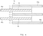
- FIG. 4 is a schematic side view illustrating a stacking step in the method for manufacturing the electrode assembly according to the embodiment of the present invention.
- FIG. 5 is a schematic side view illustrating a welding step of a negative electrode and a positive electrode in the method for manufacturing the electrode assembly according to the embodiment of the present invention.
- FIG. 6 is a schematic side view illustrating a cutting step in a method for manufacturing an electrode assembly according to another embodiment of the present invention.
- FIG. 7 is a perspective view illustrating a secondary battery according to an embodiment of the present invention.
- FIG. 1 is a perspective view illustrating an electrode assembly according to an embodiment of the present invention
- FIG. 2 is a side cross-sectional view illustrating main parts of the electrode assembly, taken along line A-A of FIG. 1 .
- a single electrode assembly 10 in which a plurality of negative electrodes 11 and positive electrodes 13 are stacked alternately and repeatedly, and separators 15 are disposed between the plurality of negative electrodes 11 and positive electrodes 13 , according to an embodiment of the present invention includes: a negative electrode tab part 20 formed on one end of the electrode assembly 10 and extending from the plurality of negative electrodes 11 ; a positive electrode bus bar 40 spaced apart from the negative electrode tab part 20 on the one end of the electrode assembly 10 and electrically connecting the plurality of the positive electrodes 13 ; a positive electrode tab part 30 formed on the other end of the electrode assembly 10 opposite to the one end and extending from the plurality of positive electrodes 13 ; and a negative electrode bus bar 50 spaced apart from the positive electrode tab part 30 on the other end of the electrode assembly 10 and electrically connecting the plurality of the negative electrodes 11 .
- the positive electrodes 13 may be an aluminum electrode collector and include a positive electrode coating portion coated with a positive electrode active material and a positive electrode non-coating portion that is not coated with the positive electrode active material.
- the positive electrode active material may be lithium-containing transition metal oxide or a lithium chalcogenide compound such as LiCoO 2 , LiNiO 2 , LiMnO 2 , and LiMnO 4 .
- the positive electrode coating portion is formed, for example, by applying the positive electrode active material onto a portion of at least one surface of the aluminum electrode collector, and other portions of the aluminum electrode collector, in which the positive electrode active material is not applied, may serve as the positive electrode non-coating portion.
- the positive electrode tab part 30 may be electrically connected to the positive electrode non-coating portion to extend from the positive electrodes 13 .
- the negative electrodes 11 may be a copper electrode collector and include a negative electrode coating portion coated with a negative electrode active material and a negative electrode non-coating portion that is not coated with the negative electrode active material.
- the negative electrode active material may be a carbon material such as crystalline carbon, amorphous carbon, carbon composite, and carbon fiber, lithium metal, a lithium alloy, or the like.
- the negative electrode coating portion is formed, for example, by applying the negative electrode active material onto a portion of at least one surface of the copper electrode collector, and other portions of the copper electrode collector, in which the negative electrode active material is not applied, may serve as the negative electrode non-coating portion.
- the negative electrode tab part 20 is electrically connected to the negative electrode non-coating portion to extend from the negative electrodes 13 .
- the separators may be manufactured, for example, by applying a polyvinylidene fluoride-hexafluoropropylene co-polymer (PVDF-HFP co-polymer) onto a base material selected from the group consisting of polyethylene (PE), polystyrene (PS), polypropylene (PP), and a co-polymer of polyethylene (PE) and polypropylene (PP).
- PVDF-HFP co-polymer polyvinylidene fluoride-hexafluoropropylene co-polymer
- the positive electrode bus bar 40 may be formed as an electrode collector extending from the positive electrodes 13 of the electrode assembly 10 so as to be spaced apart from the negative electrode tab part 20 on an end of the electrode assembly 10 in which the negative electrode tab part 20 is formed. This positive electrode bus bar 40 may electrically connect the plurality of positive electrodes 13 to enable current to flow, while spaced apart from the negative electrode tab part 20 to prevent short-circuit with the negative electrode tab part 20 .
- the positive electrode bus bar 40 may be made of an aluminum material.
- the negative electrode bus bar 50 may be formed as an electrode collector extending from the negative electrodes 11 of the electrode assembly 10 so as to be spaced apart from the positive electrode tab part 30 on an end of the electrode assembly 10 in which the positive electrode tab part 30 is formed. This negative electrode bus bar 50 may electrically connect the plurality of negative electrodes 11 to enable current to flow, while spaced apart from the positive electrode tab part 30 to prevent short-circuit with the positive electrode tab part 30 .
- the negative electrode bus bar 40 may be made of a copper material.
- heat may be accumulated to increase in temperature inside the battery due to an increasing thickness, and the accumulated heat may cause an increase in the temperature of the secondary battery.
- the positive electrode bus bar 40 and the negative electrode bus bar 50 may be formed in diagonally symmetrical positions about a central portion C of the electrode assembly 10 . That is, heat dissipation due to the flow of current may be distributed over the entirety of the electrode assembly 10 by maximizing a spaced distance between the positive electrode bus bar 40 and the negative electrode bus bar 50 , and thus there may be an effect of preventing an increase in the temperature of the secondary battery and improving safety.
- Each of the positive electrode bus bar 40 and the negative electrode bus bar 50 is formed in plurality to secure an electron transfer path uniformly over the entirety of the single electrode assembly, and thus there may be effects of preventing a deviation in current density, improving safety through heat distribution, and enhancing an output.
- an insulating member 60 such as rubber or plastic may be installed between the positive electrode bus bar 40 and the negative electrodes 11 of the electrode assembly 10 .
- the insulating member 60 may be installed between the positive electrode bus bar 40 and the negative electrodes 11 of the electrode assembly 10 so as to insulate the positive electrode bus bar 40 from the negative electrodes 11 , thereby preventing short-circuit between the positive electrode bus bar 40 and the negative electrodes 11 .
- the insulating member 60 may be installed between the negative electrode bus bar 50 and the positive electrodes 13 of the electrode assembly 10 so as to insulate the negative electrode bus bar 50 from the positive electrodes 13 , thereby preventing short-circuit between the negative electrode bus bar 50 and the positive electrodes.
- FIG. 3 is a flowchart sequentially illustrating a method for manufacturing an electrode assembly according to an embodiment of the present invention.
- the method for manufacturing the electrode assembly may include a stacking step (S 1 ), a negative electrode welding step (S 2 ), and a positive electrode welding step (S 3 ).
- FIG. 4 is a schematic side view illustrating a stacking step in the method for manufacturing the electrode assembly according to the embodiment of the present invention.
- electrodes and separators may be alternately stacked to form a single electrode stack in the stacking step (S 1 ).
- negative electrodes 11 may include negative electrode extension parts 50 a that are portions longer than positive electrodes 13 and separators 15 on one end.
- the positive electrodes 13 may include positive electrode extension parts 40 a that are portions longer than the negative electrodes 11 and the separators 15 .
- the positive electrodes 13 in which a positive electrode tab part 30 is formed on the one end, the separators 15 , and the negative electrodes 11 including the negative electrode extension parts 50 a on the one end may be stacked sequentially.
- the negative electrodes 11 in which a negative electrode tab part 20 is formed on the other end, the separators 15 , and the positive electrodes 13 including the positive electrode extension parts 40 a on the other end may be stacked sequentially.
- the stacking step may mean to sequentially stack the positive electrodes 13 in which the positive electrode tab part 30 is formed on the one end and which include the positive electrode extension parts 40 a on the other end/the separators 15 /the negative electrodes 11 which include the negative electrode extension parts 50 a on the one end and in which the negative electrode tab part 20 is formed on the other end.
- FIG. 5 is a schematic side view illustrating a welding step of a negative electrode and a positive electrode in the method for manufacturing the electrode assembly according to the embodiment of the present invention.
- the plurality of negative electrode extension parts 50 a included in the plurality of negative electrodes 11 may be welded to each other in the negative electrode welding step (S 2 ).
- the negative electrode extension parts 50 a are welded to each other, portions spaced apart from the positive electrode tab part 30 in the negative electrode extension parts 50 a may be welded.
- the positive electrode extension parts 40 a included in the plurality of positive electrodes 13 may be welded to each other in the positive electrode welding step (S 3 ).
- portions spaced apart from the negative electrode tab part 20 in the positive electrode extension parts 40 a may be welded.
- the portions spaced apart from the positive electrode tab part 30 in the negative electrode extension parts 50 a are welded, the portions spaced apart from the negative electrode tab part 20 in the positive electrode extension parts 40 a are welded, and then portions that are not welded are cut in a negative electrode cutting step and a positive electrode cutting step that will be described later.
- a risk of the short-circuit may be prevented. That is, the welded portions of each of the negative electrode extension parts 50 a and the positive electrode extension parts 40 a , remaining after being cut in the negative electrode cutting step and the positive electrode cutting step, are spaced apart from and do not contact each of the positive electrode tab part 30 and the negative electrode tab part 20 , and thus the risk of short-circuit may be eliminated.
- the welding for each of the negative electrode extension parts 50 a and the positive electrode extension parts 40 a in the negative electrode welding step (S 2 ) and the positive electrode welding step (S 3 ) may be performed through ultrasonic welding or thermal welding.
- FIG. 6 is a schematic side view illustrating a cutting step in a method for manufacturing an electrode assembly according to another embodiment of the present invention.
- a method for manufacturing an electrode assembly may further include a negative electrode cutting step of cutting portions that are not welded in the negative electrode extension parts 50 a . Also, the method may further include a positive electrode cutting step of cutting portions that are not welded in the positive electrode extension parts 40 a . By cutting the portions that are not welded in the negative electrode extension parts 50 a and the positive electrode extension parts 40 a , possibilities of both short-circuit between the negative electrode extension parts 50 a and the positive electrode tab part 30 and short-circuit between the positive electrode extension parts 40 a and the negative electrode tab part 20 may be eliminated.
- the portions that are not welded and cut out may be ends of the electrode extension parts 40 a and 50 a in a direction parallel to the electrode tab parts 20 and 30 or may be ends of the electrode extension parts 40 a and 50 a in a direction toward the electrode tab parts 20 and 30 .
- the positive electrode extension parts 40 a that are not cut in the positive electrode cutting step but welded to each other may provide a positive electrode bus bar 40 .
- the negative electrode extension parts 50 a that are not cut in the negative electrode cutting step but welded to each other may provide a negative electrode bus bar 50 .
- the method may further include a first insulating member installation step of installing an insulating member 60 between the negative electrode bus bar 50 and the positive electrodes 13 of the electrode stack to prevent short-circuit.
- the method may further include a second insulating member installation step of installing an insulating member 60 between the positive electrode bus bar 40 and the negative electrodes 11 of the electrode stack to prevent short-circuit.
- FIG. 7 is a perspective view illustrating a secondary battery according to an embodiment of the present invention.
- a secondary battery including a single electrode assembly 10 in which a plurality of negative electrodes 11 and positive electrodes 13 are stacked alternately and repeatedly, and separators 15 are disposed between the plurality of negative electrodes 11 and positive electrodes 13 , according to an embodiment of the present invention includes: a negative electrode tab part 20 formed on one end of the electrode assembly 10 and extending from the plurality of negative electrodes 11 ; a positive electrode bus bar 40 spaced apart from the negative electrode tab part 20 on the one end of the electrode assembly 10 and electrically connecting the plurality of the positive electrodes 13 ; a positive electrode tab part 30 formed on the other end of the electrode assembly 10 opposite to the one end and extending from the plurality of positive electrodes 13 ; and a negative electrode bus bar 50 spaced apart from the positive electrode tab part 30 on the other end of the electrode assembly 10 and electrically connecting the plurality of the negative electrodes 11 .
- the electrode assembly 10 may be accommodated, together with an electrolyte, in a case 3 such as a can member or a pouch.
Landscapes
- Chemical & Material Sciences (AREA)
- Chemical Kinetics & Catalysis (AREA)
- Electrochemistry (AREA)
- General Chemical & Material Sciences (AREA)
- Engineering & Computer Science (AREA)
- Manufacturing & Machinery (AREA)
- Mechanical Engineering (AREA)
- Connection Of Batteries Or Terminals (AREA)
- Secondary Cells (AREA)
Abstract
Description
Claims (11)
Applications Claiming Priority (3)
| Application Number | Priority Date | Filing Date | Title |
|---|---|---|---|
| KR10-2018-0094484 | 2018-08-13 | ||
| KR1020180094484A KR102384970B1 (en) | 2018-08-13 | 2018-08-13 | Electrode and method for electrode manufacture for the same |
| PCT/KR2019/008590 WO2020036318A1 (en) | 2018-08-13 | 2019-07-11 | Electrode assembly and method for manufacturing same electrode assembly |
Publications (2)
| Publication Number | Publication Date |
|---|---|
| US20200287196A1 US20200287196A1 (en) | 2020-09-10 |
| US11552376B2 true US11552376B2 (en) | 2023-01-10 |
Family
ID=69525549
Family Applications (1)
| Application Number | Title | Priority Date | Filing Date |
|---|---|---|---|
| US16/646,273 Active 2040-03-20 US11552376B2 (en) | 2018-08-13 | 2019-07-11 | Electrode assembly and method for manufacturing the same |
Country Status (6)
| Country | Link |
|---|---|
| US (1) | US11552376B2 (en) |
| EP (1) | EP3667798A4 (en) |
| JP (1) | JP6980982B2 (en) |
| KR (1) | KR102384970B1 (en) |
| CN (1) | CN111108639B (en) |
| WO (1) | WO2020036318A1 (en) |
Families Citing this family (5)
| Publication number | Priority date | Publication date | Assignee | Title |
|---|---|---|---|---|
| JP7249991B2 (en) * | 2020-12-24 | 2023-03-31 | プライムプラネットエナジー&ソリューションズ株式会社 | secondary battery |
| US20220384912A1 (en) * | 2021-05-27 | 2022-12-01 | Bell Textron Inc. | Thermally Efficient Pouch Cell Architecture |
| KR102839856B1 (en) * | 2021-09-30 | 2025-07-29 | 주식회사 엘지에너지솔루션 | Separator laminate and electode assembly including the same, and manufacturing method of the electode assembly |
| EP4428983A4 (en) * | 2022-04-25 | 2025-08-27 | Lg Energy Solution Ltd | ELECTRODE ARRANGEMENT AND BATTERY CELL THEREFORE |
| GB2627978A (en) * | 2023-03-10 | 2024-09-11 | Jaguar Land Rover Ltd | Frame for vehicle battery |
Citations (22)
| Publication number | Priority date | Publication date | Assignee | Title |
|---|---|---|---|---|
| JP2000058012A (en) | 1998-07-31 | 2000-02-25 | Japan Energy Corp | Flat battery and method of manufacturing the same |
| JP2001325945A (en) | 2000-03-06 | 2001-11-22 | Mitsubishi Chemicals Corp | Battery and manufacturing method thereof |
| JP2002175790A (en) | 2000-12-08 | 2002-06-21 | Matsushita Electric Ind Co Ltd | Flat battery |
| KR20060125607A (en) | 2005-06-02 | 2006-12-06 | 가부시끼가이샤 도시바 | How to fix the battery pack and the assembled battery of the assembled battery |
| KR20080038465A (en) | 2006-10-30 | 2008-05-07 | 주식회사 엘지화학 | Battery Cell with Excellent Structural Stability and Insulation Resistance |
| US20110129718A1 (en) | 2009-12-01 | 2011-06-02 | Samsung Sdi Co., Ltd. | Electrode assembly and secondary battery including the same |
| JP2012054197A (en) | 2010-09-03 | 2012-03-15 | Nec Energy Devices Ltd | Laminate battery and method for manufacturing the same |
| JP2013069417A (en) | 2011-09-20 | 2013-04-18 | Shin Kobe Electric Mach Co Ltd | Secondary battery |
| US20130130075A1 (en) | 2011-06-30 | 2013-05-23 | Lg Chem, Ltd. | Electrode assembly for secondary battery and lithium secondary battery including the same |
| JP2013178997A (en) | 2012-02-29 | 2013-09-09 | Sanyo Electric Co Ltd | Secondary battery |
| KR20140044440A (en) | 2012-10-05 | 2014-04-15 | 에스케이이노베이션 주식회사 | Battery pack |
| US20140134461A1 (en) | 2011-07-04 | 2014-05-15 | Kazuhiko Inoue | Secondary battery |
| KR20140083344A (en) | 2012-12-26 | 2014-07-04 | 에스케이이노베이션 주식회사 | Pouch type secondary battery |
| JP2014135204A (en) | 2013-01-10 | 2014-07-24 | Hitachi Vehicle Energy Ltd | Battery pack |
| US20150147629A1 (en) | 2013-11-27 | 2015-05-28 | Lg Chem, Ltd. | Electrode assembly and electrochemical device including the same |
| KR20150060830A (en) | 2012-11-09 | 2015-06-03 | 닛산 지도우샤 가부시키가이샤 | Assembled battery and method for manufacturing assembled battery |
| CN105027347A (en) | 2013-03-07 | 2015-11-04 | Nec能源元器件株式会社 | Non-aqueous electrolyte secondary battery |
| JP2016009685A (en) | 2014-06-20 | 2016-01-18 | 楊 泰和 | Electrode plate pair charging/discharging device with polygonal conductive terminal having insulated package sealing body |
| US20170069929A1 (en) | 2015-09-04 | 2017-03-09 | Samsung Sdi Co., Ltd. | Method for manufacturing rechargeable battery and rechargeable battery manufactured using the same |
| KR101789066B1 (en) | 2017-05-25 | 2017-10-23 | 주식회사 리베스트 | electrode assembly of composite structure, manufacturing method and lithium ion battery having electrode assembly |
| US20170352858A1 (en) | 2016-06-07 | 2017-12-07 | Lg Chem, Ltd. | Electrode assembly including electrode plates with electrode plate extensions |
| JP2018092955A (en) | 2016-02-01 | 2018-06-14 | 株式会社東芝 | Secondary battery, assembled battery, battery pack, and vehicle |
-
2018
- 2018-08-13 KR KR1020180094484A patent/KR102384970B1/en active Active
-
2019
- 2019-07-11 CN CN201980004544.6A patent/CN111108639B/en active Active
- 2019-07-11 JP JP2020521370A patent/JP6980982B2/en active Active
- 2019-07-11 WO PCT/KR2019/008590 patent/WO2020036318A1/en not_active Ceased
- 2019-07-11 EP EP19850080.3A patent/EP3667798A4/en active Pending
- 2019-07-11 US US16/646,273 patent/US11552376B2/en active Active
Patent Citations (34)
| Publication number | Priority date | Publication date | Assignee | Title |
|---|---|---|---|---|
| JP2000058012A (en) | 1998-07-31 | 2000-02-25 | Japan Energy Corp | Flat battery and method of manufacturing the same |
| JP2001325945A (en) | 2000-03-06 | 2001-11-22 | Mitsubishi Chemicals Corp | Battery and manufacturing method thereof |
| JP2002175790A (en) | 2000-12-08 | 2002-06-21 | Matsushita Electric Ind Co Ltd | Flat battery |
| KR20060125607A (en) | 2005-06-02 | 2006-12-06 | 가부시끼가이샤 도시바 | How to fix the battery pack and the assembled battery of the assembled battery |
| US20060275658A1 (en) | 2005-06-02 | 2006-12-07 | Kabushiki Kaisha Toshiba | Battery pack of assembled battery and fixing method of assembled battery |
| KR20080038465A (en) | 2006-10-30 | 2008-05-07 | 주식회사 엘지화학 | Battery Cell with Excellent Structural Stability and Insulation Resistance |
| US20110129718A1 (en) | 2009-12-01 | 2011-06-02 | Samsung Sdi Co., Ltd. | Electrode assembly and secondary battery including the same |
| KR20110061281A (en) | 2009-12-01 | 2011-06-09 | 삼성에스디아이 주식회사 | Electrode assembly and secondary battery having same |
| JP2012054197A (en) | 2010-09-03 | 2012-03-15 | Nec Energy Devices Ltd | Laminate battery and method for manufacturing the same |
| US20130130075A1 (en) | 2011-06-30 | 2013-05-23 | Lg Chem, Ltd. | Electrode assembly for secondary battery and lithium secondary battery including the same |
| CN103222098A (en) | 2011-06-30 | 2013-07-24 | 株式会社Lg化学 | Electrode assembly for secondary battery and lithium secondary battery comprising the same |
| US20140134461A1 (en) | 2011-07-04 | 2014-05-15 | Kazuhiko Inoue | Secondary battery |
| JP6007907B2 (en) | 2011-07-04 | 2016-10-19 | 日本電気株式会社 | Secondary battery |
| JP2013069417A (en) | 2011-09-20 | 2013-04-18 | Shin Kobe Electric Mach Co Ltd | Secondary battery |
| JP2013178997A (en) | 2012-02-29 | 2013-09-09 | Sanyo Electric Co Ltd | Secondary battery |
| KR20140044440A (en) | 2012-10-05 | 2014-04-15 | 에스케이이노베이션 주식회사 | Battery pack |
| US20150303415A1 (en) | 2012-11-09 | 2015-10-22 | Nissan Motor Co., Ltd. | Assembled battery and method for manufacturing assembled battery |
| KR20150060830A (en) | 2012-11-09 | 2015-06-03 | 닛산 지도우샤 가부시키가이샤 | Assembled battery and method for manufacturing assembled battery |
| KR20140083344A (en) | 2012-12-26 | 2014-07-04 | 에스케이이노베이션 주식회사 | Pouch type secondary battery |
| JP2014135204A (en) | 2013-01-10 | 2014-07-24 | Hitachi Vehicle Energy Ltd | Battery pack |
| CN105027347A (en) | 2013-03-07 | 2015-11-04 | Nec能源元器件株式会社 | Non-aqueous electrolyte secondary battery |
| US20150380716A1 (en) | 2013-03-07 | 2015-12-31 | Nec Energy Devices, Ltd. | Non-aqueous electrolyte secondary battery |
| EP2966721A1 (en) | 2013-03-07 | 2016-01-13 | NEC Energy Devices, Ltd. | Non-aqueous electrolyte secondary battery |
| CN104904053A (en) | 2013-11-27 | 2015-09-09 | 株式会社Lg化学 | Electrode assembly and electrochemical device containing same |
| US20150147629A1 (en) | 2013-11-27 | 2015-05-28 | Lg Chem, Ltd. | Electrode assembly and electrochemical device including the same |
| JP2016009685A (en) | 2014-06-20 | 2016-01-18 | 楊 泰和 | Electrode plate pair charging/discharging device with polygonal conductive terminal having insulated package sealing body |
| US20170069929A1 (en) | 2015-09-04 | 2017-03-09 | Samsung Sdi Co., Ltd. | Method for manufacturing rechargeable battery and rechargeable battery manufactured using the same |
| KR20170028789A (en) | 2015-09-04 | 2017-03-14 | 삼성에스디아이 주식회사 | Method of manufacturing rechargeable battery and rechargeable battery |
| JP2018092955A (en) | 2016-02-01 | 2018-06-14 | 株式会社東芝 | Secondary battery, assembled battery, battery pack, and vehicle |
| EP3413391A1 (en) | 2016-02-01 | 2018-12-12 | Kabushiki Kaisha Toshiba | Secondary battery, assembled battery, battery pack, and vehicle |
| US20170352858A1 (en) | 2016-06-07 | 2017-12-07 | Lg Chem, Ltd. | Electrode assembly including electrode plates with electrode plate extensions |
| KR20170138253A (en) | 2016-06-07 | 2017-12-15 | 주식회사 엘지화학 | Electrode Assembly Comprising Electrode Plates Having Electrode Plate Extending Part |
| KR101789066B1 (en) | 2017-05-25 | 2017-10-23 | 주식회사 리베스트 | electrode assembly of composite structure, manufacturing method and lithium ion battery having electrode assembly |
| US20200235436A1 (en) | 2017-05-25 | 2020-07-23 | Libest Inc. | Composite electrode assembly and lithium-ion secondary battery including the same |
Non-Patent Citations (3)
| Title |
|---|
| Extended European Search Report including Written Opinion for EP19850080.3 dated Nov. 30, 2020; 7 pages. |
| International Search Report from Application No. PCT/KR2019/008590 dated Oct. 17, 2019, 2 pages. |
| Search Report dated Oct. 11, 2022 from the Office Action for Chinese Application No. 201980004544.6 dated Oct. 17, 2022, 3 pages. [See p. 1-2, categorizing the cited references]. |
Also Published As
| Publication number | Publication date |
|---|---|
| KR102384970B1 (en) | 2022-04-11 |
| CN111108639B (en) | 2023-12-12 |
| JP6980982B2 (en) | 2021-12-15 |
| JP2020537322A (en) | 2020-12-17 |
| EP3667798A1 (en) | 2020-06-17 |
| CN111108639A (en) | 2020-05-05 |
| EP3667798A4 (en) | 2020-12-30 |
| KR20200018977A (en) | 2020-02-21 |
| WO2020036318A1 (en) | 2020-02-20 |
| US20200287196A1 (en) | 2020-09-10 |
Similar Documents
| Publication | Publication Date | Title |
|---|---|---|
| US12278326B2 (en) | Secondary battery and method for manufacturing the same | |
| US11552376B2 (en) | Electrode assembly and method for manufacturing the same | |
| EP0949699B1 (en) | Electrical connection structure in a lithium secondary battery | |
| US11349182B2 (en) | Electrode assembly | |
| US8574752B2 (en) | Electrode assembly and rechargeable battery using the same | |
| US11056714B2 (en) | Secondary battery | |
| KR101181804B1 (en) | Electrode assembly, and rechargeable battery using thereof | |
| KR101431726B1 (en) | Electrode Assembly of Improved Safety And Secondary Battery with the Same | |
| US20230187739A1 (en) | Secondary battery | |
| EP2421074B1 (en) | Jelly roll and electrode assembly having the same | |
| KR102057084B1 (en) | Secondary battery | |
| EP4579867A1 (en) | Electrode assembly and secondary battery including same | |
| KR20260017852A (en) | rechargeable battery and electrode plate of the same |
Legal Events
| Date | Code | Title | Description |
|---|---|---|---|
| FEPP | Fee payment procedure |
Free format text: ENTITY STATUS SET TO UNDISCOUNTED (ORIGINAL EVENT CODE: BIG.); ENTITY STATUS OF PATENT OWNER: LARGE ENTITY |
|
| AS | Assignment |
Owner name: LG CHEM, LTD., KOREA, REPUBLIC OF Free format text: ASSIGNMENT OF ASSIGNORS INTEREST;ASSIGNORS:CHOI, SOON HYUNG;LEE, SU RIM;KIM, SEOK KOO;REEL/FRAME:052093/0068 Effective date: 20200120 |
|
| STPP | Information on status: patent application and granting procedure in general |
Free format text: DOCKETED NEW CASE - READY FOR EXAMINATION |
|
| AS | Assignment |
Owner name: LG ENERGY SOLUTION, LTD., KOREA, REPUBLIC OF Free format text: ASSIGNMENT OF ASSIGNORS INTEREST;ASSIGNOR:LG CHEM, LTD.;REEL/FRAME:058295/0068 Effective date: 20211027 Owner name: LG ENERGY SOLUTION, LTD., KOREA, REPUBLIC OF Free format text: ASSIGNMENT OF ASSIGNOR'S INTEREST;ASSIGNOR:LG CHEM, LTD.;REEL/FRAME:058295/0068 Effective date: 20211027 |
|
| STPP | Information on status: patent application and granting procedure in general |
Free format text: NON FINAL ACTION MAILED |
|
| STPP | Information on status: patent application and granting procedure in general |
Free format text: RESPONSE TO NON-FINAL OFFICE ACTION ENTERED AND FORWARDED TO EXAMINER |
|
| STPP | Information on status: patent application and granting procedure in general |
Free format text: NOTICE OF ALLOWANCE MAILED -- APPLICATION RECEIVED IN OFFICE OF PUBLICATIONS |
|
| STPP | Information on status: patent application and granting procedure in general |
Free format text: NOTICE OF ALLOWANCE MAILED -- APPLICATION RECEIVED IN OFFICE OF PUBLICATIONS |
|
| STPP | Information on status: patent application and granting procedure in general |
Free format text: PUBLICATIONS -- ISSUE FEE PAYMENT VERIFIED |
|
| STCF | Information on status: patent grant |
Free format text: PATENTED CASE |