US1155221A - Mail-bag catcher. - Google Patents
Mail-bag catcher. Download PDFInfo
- Publication number
- US1155221A US1155221A US84812114A US1914848121A US1155221A US 1155221 A US1155221 A US 1155221A US 84812114 A US84812114 A US 84812114A US 1914848121 A US1914848121 A US 1914848121A US 1155221 A US1155221 A US 1155221A
- Authority
- US
- United States
- Prior art keywords
- finger
- fork
- shaft
- trip
- Prior art date
- Legal status (The legal status is an assumption and is not a legal conclusion. Google has not performed a legal analysis and makes no representation as to the accuracy of the status listed.)
- Expired - Lifetime
Links
- 238000012986 modification Methods 0.000 description 3
- 230000004048 modification Effects 0.000 description 2
- UPYKUZBSLRQECL-UKMVMLAPSA-N Lycopene Natural products CC(=C/C=C/C=C(C)/C=C/C=C(C)/C=C/C1C(=C)CCCC1(C)C)C=CC=C(/C)C=CC2C(=C)CCCC2(C)C UPYKUZBSLRQECL-UKMVMLAPSA-N 0.000 description 1
- 230000015572 biosynthetic process Effects 0.000 description 1
- 235000005473 carotenes Nutrition 0.000 description 1
- 238000010276 construction Methods 0.000 description 1
- 239000002244 precipitate Substances 0.000 description 1
- NCYCYZXNIZJOKI-UHFFFAOYSA-N vitamin A aldehyde Natural products O=CC=C(C)C=CC=C(C)C=CC1=C(C)CCCC1(C)C NCYCYZXNIZJOKI-UHFFFAOYSA-N 0.000 description 1
Images

Classifications
-
- B—PERFORMING OPERATIONS; TRANSPORTING
- B61—RAILWAYS
- B61K—AUXILIARY EQUIPMENT SPECIALLY ADAPTED FOR RAILWAYS, NOT OTHERWISE PROVIDED FOR
- B61K1/00—Transferring passengers, articles, or freight to and from moving trains; Slipping or coupling vehicles from or to moving trains
- B61K1/02—Transferring passengers, articles, or freight to and from moving trains; Slipping or coupling vehicles from or to moving trains transferring articles to and from moving trains, e.g. mailbag catchers
Definitions
- PatentedSept. 28, 1915 are PatentedSept. 28, 1915.
- This invention relates to improvements in railway mail bag or pouch catchers, as in receiving or taking the mail bag or pouch at a station, it being. equally adapted for taking or catching the pouch'upon a post as upon a car.
- the invention has for its object to greatly simplify theconstruction and arrangement of the parts and to facilitate their operation and application for use i
- a further object is to promote celerity of action and to insure certainty of the catching action of the device.
- a still further object is to carry out the aforesaid ends with expedition and despatch.
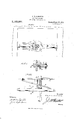
- Figure 1 is a plan view of my mail pouch catcher as set for catching or receiving a mail pouch.
- Fig. 2 is a similar view thereof as when not set or out of use.
- Fig.3 is acentral vertical transverse section thereof. it be ing in set position. the section being taken on the line 3-3 of Fig. 1.
- Fig. 4 is a longitudinal section taken on the line 44L of Fig. 1.
- Fig.5 is a transverse section taken on the line 5-5 of Fig. 1.
- Fig. 6 is a plan view of 1 a modification of my invention, the -mail hingedly connected together.
- a bifurcated bar or fork 9 receives and is suitably fulcrumed, as at 10, upon the sleeve or shaft 3 so as to suitably pivot thereon, an opening 11 being provided in said fork for its application to said shaft and which opening is somewhat elongated to allow of obliquity or limited arcuate movement of the fork,.thepurpose of which will be presently apparent.
- the fork or member 9 is automatically" or resiliently held or drawn toward one sideof'the catcher and so as to intercept the longitudinal medial line thereof by the action of preferably'duplicate springs 12 suitably connected thereto and to fixed opposite points, as upon the finger, as
- a trip or retaining member 14 for the fork, said trip being preferably in the form of a cylindrical pin with its pivot 10*- passing vertically and transversely therethrough near one end, whilenear the opposite end ofsai d trip is a shoulder 15 as the resultantof reducing the trip in the direc tion of thelatter end,the function of which shoulder will be presently seen.
- the finger 1 6 has an aper ture 17 arranged toreceive and provide for the movement therein of the trip or retain the retaining member or trip being arranged to engage the inner edge of the aperture of the finger, as will appear especially from Fig. 1.
- the trip or retaining member 14 is also controlled by a resilient member or spring l7 suitably connected thereto and to' a fixed point, as on the finger, so as to effect the automatic engagement of the shoulder f the trip withthe edge of the aperture in the finger as the fork is moved away from the finger, as in positioning the fork preliminary to the catching of the mail pouch, the latter being received or caught between the finger and fork.
- a resilient member or spring l7 suitably connected thereto and to' a fixed point, as on the finger, so as to effect the automatic engagement of the shoulder f the trip withthe edge of the aperture in the finger as the fork is moved away from the finger, as in positioning the fork preliminary to the catching of the mail pouch, the latter being received or caught between the finger and fork.
- the mail pouch contactsowith the trip 14 and disengages the shoulderof the latter from the finger, accordingly providing for the instant automatic movement'of the fork toward the 'finger,causing the forcible gripping of the mail pouch between the finger and fork.
- the fork may have a sliding movement upon the sleeve or shaft bearing the same and be hinged or pivoted at its inner end to the finger, as at 15, which will provide for the fork having a like action-as aforesaid.
- a device of the type described including a suspending pivoted member having a fixed shaft at right angles thereto, a second shaft sleeved upon the aforesaid shaft and having fixed thereto a finger, a resiliently actuated fork positioned to have movement upon the sleeved shaft, and a resiliently actuated trip pivoted to said fork and having a shoulder at its free end, said free end of the trip being movable through saidfinger and having its said shoulder engaging the finger.
- a device of the type described including a suspending pivoted member having a fixed shaft at right angles thereto, a second shaft turning upon the aforesaid shaft and having fixed theretoat one end a finger, a
- a device of the type described including a suspending pivoted member having a fixed shaft at right angles thereto, a second shaft sleeved upon the aforesaid shaft and having fixed thereto a finger, a resiliently actuated fork positioned to have. movement uponsaid second shaft, opposite said finger, means effecting hinged for pivoted connection between said fork and.
- said lio shaft at right angles thereto, a tubular shaft carried by and arranged to turn upon the aforesaid shaft and having fixed to one end a finger, a resiliently controlled fork fulcrumedupon said tubular shaft and itself having fulcrumed therein a resiliently controlled'trip having a shoulder near its free end, said-finger having an aperture receiving said free end of the trip, the shoulder of said trip arranged to engage said finger at the edge of said aperture 7 r 5.
- a device of the type described including a suspending pivoted member having a fixed shaft at right angles thereto, a fixed finger, means providing for carrying said finger upon said shaft, means for fixing the position of said finger-carrying means,-;wi-th respect to said pivoted member, a resiliently actuated fork positioned to have movement toward said finger at one end, and a re siliently actuated trip pivoted to said fork and having a shoulder near its free end, said free end of the trip being movable through said finger and having its shoulder engaging said finger.
- a device of the type described including a suspending pivoted member having a fixed shaft at right-angles thereto, a fix ed finger, means providing for carrying said finger upon said shaft, means for fixing the position of the said finger-carrying means with respect to said suspending pivoted member, a resiliently controlled fork posi- Copies of this patent may be obtained for five cents each, by addressing the Commissioner of Patents,
Landscapes
- Engineering & Computer Science (AREA)
- Mechanical Engineering (AREA)
- Purses, Travelling Bags, Baskets, Or Suitcases (AREA)
Description
A. W. DICKERSON.
MAIL BAG CATCHER. APPLICA TION FILED JUNE 30, 19M.
PatentedSept. 28, 1915.
2 SHEETS-SHEET I.
' Svwwwtoz A/be t W. Dicker-Jan COLUMBIA PLANOGRAPH 60., WASHINGTON, D. c.
A. W. DICKERSON.
MAIL BAG CATCHER.
APPLICATION FILED JUNE 30. I914.
1,155,221. PatentedSept. 28, 1915.
2 SHEETS-SHEET 2 2 /474 A/brt W. Dz'ckera 77.
Wi hwmo COLUMBIA PLANOORAPH CD-,\VA5H|NOTON. D. c.
I stantially as hereinafter fully disclosedand ALBERT w. nronnnson, on enmon, OHIO.
MAIL-BAG carotene.
Specification of Letters Patent. 7 Patented Sept. 28, 1915.
Application filed June so, 1914. Serial No; 818,121.
T 0 all whom it may concern:
Be it knownjthat I, ALBERT W. DICKER- son, a citizen of the United States, residing at Galion, in the county of Morrow and State of Ohio, have invented certain new and useful Improvements in Mail- Bag Catchers, of which the following is a specification. I p
This invention relates to improvements in railway mail bag or pouch catchers, as in receiving or taking the mail bag or pouch at a station, it being. equally adapted for taking or catching the pouch'upon a post as upon a car.
The invention has for its object to greatly simplify theconstruction and arrangement of the parts and to facilitate their operation and application for use i A further object is to promote celerity of action and to insure certainty of the catching action of the device.
A still further object is to carry out the aforesaid ends with expedition and despatch.
The invention, therefore, consists of the combination and arrangement of parts subdefined by the appended claims. 1
While in the accompanying drawings 1s illustrated the preferred embodimentof my invention, it will be understood that I do not restrict myself in these particulars. as any changes or modifications maybe made therein which may fall: within the scope of the claims without departing from the'spirit of my invention, and in which drawings:
Figure 1 is a plan view of my mail pouch catcher as set for catching or receiving a mail pouch. Fig. 2 is a similar view thereof as when not set or out of use. Fig.3 is acentral vertical transverse section thereof. it be ing in set position. the section being taken on the line 3-3 of Fig. 1. Fig. 4 is a longitudinal section taken on the line 44L of Fig. 1. Fig.5 is a transverse section taken on the line 5-5 of Fig. 1. Fig. 6 is a plan view of 1 a modification of my invention, the -mail hingedly connected together.
In carrying out "my invention II suitably pouch catching members being shown as,
fix to theusual suspendingpivoted,member l or bar 1, about centrally thereof and at right or hung in the mannerwell understood transversely of the entrance or doorway of a mail car, at the upper end thereof; The bar or member 1 has projecting therefrom within convenient grasp of the operator at hand bar 4 for the suitable manipulation of the catcher. T he sleeve or shaft 8 has fixed thereto, at one end, a disk5, which, however, may be an arm, having an aperture 6 therein, and in the baror member 1 is an aperture 7 into registration or coincidence with which is arranged to be brought the aforesaid aperture by suitably turning the mail pouch catcher, as in reversing the same to accommodate the direction in which the car is to be run,'as will be appreciated. A pin Sis, ,of course, inserted into these apertures when thus brought into registrationor coincidence to maintain the catcher in fixed relation with respect to the carrying or pivoting bar 1. 1
A bifurcated bar or fork 9 receives and is suitably fulcrumed, as at 10, upon the sleeve or shaft 3 so as to suitably pivot thereon, an opening 11 being provided in said fork for its application to said shaft and which opening is somewhat elongated to allow of obliquity or limited arcuate movement of the fork,.thepurpose of which will be presently apparent. The fork or member 9 is automatically" or resiliently held or drawn toward one sideof'the catcher and so as to intercept the longitudinal medial line thereof by the action of preferably'duplicate springs 12 suitably connected thereto and to fixed opposite points, as upon the finger, as
clearly seen in Fig. 8.
Suitably fulcrumed'at or near one end in an elongated opening 13 in the fork or member 9 is a trip or retaining member 14. for the fork, said trip being preferably in the form of a cylindrical pin with its pivot 10*- passing vertically and transversely therethrough near one end, whilenear the opposite end ofsai d trip is a shoulder 15 as the resultantof reducing the trip in the direc tion of thelatter end,the function of which shoulder will be presently seen.
A finger 16 of preferably the general outline as disclosed, being ofthe approximate contour of the fork,;it, however, havinggbut a single or centrattine-like formation, is suitably fixed to the sleeve or shaft 3 at that end of the latter opposite which "the fork is applied. The finger 1 6 has an aper ture 17 arranged toreceive and provide for the movement therein of the trip or retain the retaining member or trip being arranged to engage the inner edge of the aperture of the finger, as will appear especially from Fig. 1. The trip or retaining member 14: is also controlled by a resilient member or spring l7 suitably connected thereto and to' a fixed point, as on the finger, so as to effect the automatic engagement of the shoulder f the trip withthe edge of the aperture in the finger as the fork is moved away from the finger, as in positioning the fork preliminary to the catching of the mail pouch, the latter being received or caught between the finger and fork. At this juncture the mail pouch contactsowith the trip 14 and disengages the shoulderof the latter from the finger, accordingly providing for the instant automatic movement'of the fork toward the 'finger,causing the forcible gripping of the mail pouch between the finger and fork.
, In the-modification as suggested by Fig 6, it will be observed that,-in lieu ofthe above described or preferred form of applyi g the fork, the latter may have a sliding movement upon the sleeve or shaft bearing the same and be hinged or pivoted at its inner end to the finger, as at 15, which will provide for the fork having a like action-as aforesaid.
- In operation, by grasping thehand bar of the pivoting bar land suitablv disposing the catcher with the forward endthereof facing in the direction of the mail pouch, supposedly suspended from the usual post (not shown) positioned contiguous to the railway track, such mail pouch will be received or caught between the fork and finger/of the catcher. as the mail car passes the mail- .pouch-suspending post, and as the mail pouch isthus taken from the latter said mail pouch will, by reason of the precipitate action of the latter, forcibly contact the trip 14:, which action will accordingly disengage the shoulder of said trip from the edge of the aperture 17, allowing the trip to have movement in said aperture with the thrusting of the fork toward the finger under the action of its spring, as before explained, the resultant being the gripping of the mail pouch between said 'fork and finger. By further actuating the catcher, by the same means, ,the catcher may be disposed, with the effectively held mail pouch, so that the latter may be brought within theconvenientreach of the operator for removal into the car, as will be readily appreciated.
It is apparent that my catcher maybe equally suspended in position from a mailpouch-suspending post, instead of upon the car,for taking a mail pouch therefrom into a car. r
It is thought that the characteristic features of my invention of simplicity of construction of the parts, of its ready actuation,
and of effectiveness of catching the mail pouch and retaining the mail pouch after caught have all been made clearly apparent from the foregoing description and the accompanying illustration.
I claim:
1. A device of the type described, including a suspending pivoted member having a fixed shaft at right angles thereto, a second shaft sleeved upon the aforesaid shaft and having fixed thereto a finger, a resiliently actuated fork positioned to have movement upon the sleeved shaft, and a resiliently actuated trip pivoted to said fork and having a shoulder at its free end, said free end of the trip being movable through saidfinger and having its said shoulder engaging the finger. 7
2. A device of the type described, including a suspending pivoted member having a fixed shaft at right angles thereto, a second shaft turning upon the aforesaid shaft and having fixed theretoat one end a finger, a
resiliently actuated fork positioned tohave movement upon said second shaft opposite said finger, and a resiliently actuated trlp pivoted in said fork and having a Shoulder at'its free end, said trip being received by an aperture in Saidfinger, and its said shoulder engaging the finger, at the'edge of said aperture. V
'3. A device of the type described, including a suspending pivoted member having a fixed shaft at right angles thereto, a second shaft sleeved upon the aforesaid shaft and having fixed thereto a finger, a resiliently actuated fork positioned to have. movement uponsaid second shaft, opposite said finger, means effecting hinged for pivoted connection between said fork and. said lio shaft at right angles thereto, a tubular shaft carried by and arranged to turn upon the aforesaid shaft and having fixed to one end a finger, a resiliently controlled fork fulcrumedupon said tubular shaft and itself having fulcrumed therein a resiliently controlled'trip having a shoulder near its free end, said-finger having an aperture receiving said free end of the trip, the shoulder of said trip arranged to engage said finger at the edge of said aperture 7 r 5. A device of the type described, including a suspending pivoted member having a fixed shaft at right angles thereto, a fixed finger, means providing for carrying said finger upon said shaft, means for fixing the position of said finger-carrying means,-;wi-th respect to said pivoted member, a resiliently actuated fork positioned to have movement toward said finger at one end, and a re siliently actuated trip pivoted to said fork and having a shoulder near its free end, said free end of the trip being movable through said finger and having its shoulder engaging said finger.
6. A device of the type described, including a suspending pivoted member having a fixed shaft at right-angles thereto, a fix ed finger, means providing for carrying said finger upon said shaft, means for fixing the position of the said finger-carrying means with respect to said suspending pivoted member, a resiliently controlled fork posi- Copies of this patent may be obtained for five cents each, by addressing the Commissioner of Patents,
' Washington, D. 0.
Priority Applications (1)
| Application Number | Priority Date | Filing Date | Title |
|---|---|---|---|
| US84812114A US1155221A (en) | 1914-06-30 | 1914-06-30 | Mail-bag catcher. |
Applications Claiming Priority (1)
| Application Number | Priority Date | Filing Date | Title |
|---|---|---|---|
| US84812114A US1155221A (en) | 1914-06-30 | 1914-06-30 | Mail-bag catcher. |
Publications (1)
| Publication Number | Publication Date |
|---|---|
| US1155221A true US1155221A (en) | 1915-09-28 |
Family
ID=3223283
Family Applications (1)
| Application Number | Title | Priority Date | Filing Date |
|---|---|---|---|
| US84812114A Expired - Lifetime US1155221A (en) | 1914-06-30 | 1914-06-30 | Mail-bag catcher. |
Country Status (1)
| Country | Link |
|---|---|
| US (1) | US1155221A (en) |
-
1914
- 1914-06-30 US US84812114A patent/US1155221A/en not_active Expired - Lifetime
Similar Documents
| Publication | Publication Date | Title |
|---|---|---|
| US1155221A (en) | Mail-bag catcher. | |
| US1017976A (en) | Automatic mail-bag catcher and deliverer. | |
| US863326A (en) | Mail-bag catcher. | |
| US1246142A (en) | Rail-tongs. | |
| US1273575A (en) | Mail-bag-transferring mechanism. | |
| US993952A (en) | Mail-bag catching and delivering device. | |
| US1206654A (en) | Mail-bag catching and delivering device. | |
| US446550A (en) | Device for catching mail-bags | |
| US814090A (en) | Mail-bag catcher. | |
| US459190A (en) | Mail-bag deliverer | |
| US695252A (en) | Mail-bag catcher. | |
| US489276A (en) | Device for catching mail-bags | |
| US1321327A (en) | Mail-bag receiving and delivering apparatus | |
| US1337956A (en) | Mail-transferring apparatus | |
| US1051145A (en) | Safety appliance for mail-bags. | |
| US659098A (en) | Apparatus for gripping and delivering mail-bags. | |
| US1065236A (en) | Releasing device for car-curtains. | |
| US903407A (en) | Mail-bag-delivery apparatus. | |
| US1400114A (en) | Mail-bag catching and delivering apparatus | |
| US903035A (en) | Mail-bag catcher and deliverer. | |
| US480385A (en) | Mail-bag catcher and deliverer | |
| US1069718A (en) | Mail-bag catcher. | |
| US1278355A (en) | Mail-catcher. | |
| US919911A (en) | Mail-bag catcher or transferrer. | |
| US677978A (en) | Machine for transferring mail-bags. |