US1155080A - Vignetter for cameras. - Google Patents
Vignetter for cameras. Download PDFInfo
- Publication number
- US1155080A US1155080A US69927612A US1912699276A US1155080A US 1155080 A US1155080 A US 1155080A US 69927612 A US69927612 A US 69927612A US 1912699276 A US1912699276 A US 1912699276A US 1155080 A US1155080 A US 1155080A
- Authority
- US
- United States
- Prior art keywords
- casing
- members
- plate
- blending
- cameras
- Prior art date
- Legal status (The legal status is an assumption and is not a legal conclusion. Google has not performed a legal analysis and makes no representation as to the accuracy of the status listed.)
- Expired - Lifetime
Links
- 238000002156 mixing Methods 0.000 description 16
- 239000004744 fabric Substances 0.000 description 4
- 238000010276 construction Methods 0.000 description 2
- 230000000694 effects Effects 0.000 description 2
- 230000008878 coupling Effects 0.000 description 1
- 238000010168 coupling process Methods 0.000 description 1
- 238000005859 coupling reaction Methods 0.000 description 1
- 230000003247 decreasing effect Effects 0.000 description 1
- 239000000203 mixture Substances 0.000 description 1
- 230000010355 oscillation Effects 0.000 description 1
- 230000000717 retained effect Effects 0.000 description 1
Images


Classifications
-
- G—PHYSICS
- G03—PHOTOGRAPHY; CINEMATOGRAPHY; ANALOGOUS TECHNIQUES USING WAVES OTHER THAN OPTICAL WAVES; ELECTROGRAPHY; HOLOGRAPHY
- G03B—APPARATUS OR ARRANGEMENTS FOR TAKING PHOTOGRAPHS OR FOR PROJECTING OR VIEWING THEM; APPARATUS OR ARRANGEMENTS EMPLOYING ANALOGOUS TECHNIQUES USING WAVES OTHER THAN OPTICAL WAVES; ACCESSORIES THEREFOR
- G03B17/00—Details of cameras or camera bodies; Accessories therefor
- G03B17/02—Bodies
- G03B17/12—Bodies with means for supporting objectives, supplementary lenses, filters, masks, or turrets
Definitions
- This invention relates to cameras, and more particularly to portrait cameras, and has as its object to provide an improved vignetting device for use in connection with such cameras, the device being so construct ed as to perfectly blend the backgrounds of a number of photographic impressions made upon a single sensitized plate or film.
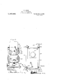
- Figure 1 is a side elevation, partly in section, of the improved device;
- Fig. 2 is a plan view with the hood or shield and the bellows portion broken away;
- Fig. 3 is a front elevation;
- Fig. 1 is a transverse section on the line 44 of Fig. 5;
- Fig. 5 is a vertical longitudinal sectional view through the camera.
- the improved device comprises a base including spaced longitudinal rails 10 11 and transverse members 12-13, the latter being mortised into the rails and perforated to receiveholding screws or other fastening devices whereby the frame may be attached to a supporting standard.
- the standard may be of any suitable form, and will preferably be an ordinary camera support, a portion of which is indicated at 14 of the usual construction.
- the camera support forms no part of the present invention, and it is not deemed necessary therefore, to further illustrate the same.
- the side rails 1011 are connected at the rear by a transverse member 15, and a transverse plate or board 16.
- casing 23 Located upon the rails 1011, at their forward ends is casing 23, having its front open and provided with vertical guideways 24 to receive a sliding member 25, the latter having an opening to receive the lens represented conventionally at 26.
- the member 21 is slidable vertically in the guideways 21 so that the lens may be adjusted vertically to any required extent.
- the member 25 is provided with stops 27 in the rear side to limit the upward movement.
- the transverse members 1213 project beyond the sides of the members 1011 and are notched in their upper faces to form guides for slidable members 128129 which ex tend in advanceof the members 1011 and carry a casing 17 at their forward ends.
- the members 128129 being slidable relative to the members 1011 and carrying the casing 17, it will be obvious that the latter is adjustable toward and away from the casing 23 by simply adjusting the members 128 and 129.
- the casing 17 extends the full width of the base frame including the members 12S129 and is formed with an apertured front 18 and a reduced forwardly extending projecting portion 19.
- the portion 19 is provided with guideways 20 at its juncture with the casing 17 to slidably receive an apertured plate, and is likewise provided with guideways 21 at its forward side to slidably receive blending plates.
- the opening in the front 18 of the casing 17 is relatively large and through this opening the light passes to the lens from the subject, and by providing a plurality of plates having openings of varying sizes, the opening may be increased or decreased in size as required.
- the casing 17 is suitably supported by braces 22 from the sliding members 128 129 as shown.
- the guideways 21 likewise provide means for slidably supporting blending plates having various sizes and forms of openings and adapted to be moved to control the light rays and to blend the impression upon the plate, as hereafter explained.
- the rail 28 is connected rigidly to the rear transverse member 15 of the base, and to the bottom of the casing 23, while the latter is rigidly supported upon the rails 1011.
- the rails 1011 are provided with inwardly directed tracks upon which a frame 29 is arranged to slide. Rigidly supported upon the frame 29 is another casing 30 correspending in outline to the casing 23, and ar-' ranged to support the plate holder.
- a bellows device Connected to the frames 23-30, is a bellows device represented as a whole at 34, which while permitting the frame 30 to be adjusted toward and away from the frame 23, excludes the light in the usual manner.
- corner plates 89 Connected to the forward upper corners of the casing 23, are corner plates 89 having eyes to receive a Ushaped wire 90 which extends toward the frame or casing 17 and serves asa support for a fabric hood represented conventionally at 91.
- the hood is fastened at its lower edge to the members 128 129 and at its forward edge to the rear end of the casing 17, and is adapted to be detachably connected to the casing 23 by rings and hooks indicated at 92.
- the guard cloth 91 may be readily connected and disconnected when required, and shuts out the light between the casings 23 and 17.
- the space between the casings 17 and 23 is further occupied by diagonal members 93 to prevent the collapse of the fabric covering.
- the braces 22 are provided with vertical obliquely disposed members 94 which serve to stop all reflected light and prevent it from reaching the sensitive plate.
- the front 18 is designed to receive slides having various sizes of openings, one of the slides being represented conventionally at 108 to enable the amount of light which is admitted to be controlled, as will be obqus- Under some circumstances it may be necessary to adjust the serrated edge of the blending plate farther from the lens and to accomplish this a wedge block 109 is provided and adapted to be inserted between the blending plate and the slide as illustrated in Figs. 1, 3 and 5, this block being connected by a chain 110 with the casing 19.
- the members 128 and 129 are connected at their forward ends by a cross bar 130. and likewise connected by an intermediate cross bar 131.
- a section of fabric 122 is attached permanently to the bottom of the members 128 and 129, and to the cross members 130 and 13.1, and operates to exclude the light at the bottom of the device.
- a plate 123 Connected to the inner faces of the members 12 8 a d 1.2. a plate 123 and extending rearwardly of the cross bar 131 upon which it is supported at its rear.
- the inner faces of the members 128 and 129 are recessed longitudinally to receive the side edges of another shut-off plate 124.
- the plate 124 is movably coupled to the frame 23 by a cord 125, the cord being attached at its ends to t e fram and. ead ng. r. a blo k 26-
- a slide 99 Slidably disposed in the guideways 21 of the projecting portion 19 of the forward casing, is a slide 99 having vertical guides 100 and a transverse guide 101, the guides being designed to support various forms and sizes of blending plates.
- the blending plates may be of any required form and may be varied to any required extent.
- One of the blending. plates is represented at 102 and reduced at the lower end to engage the member 101, and concaved at the upper side with V-shaped points 103 in the concaved portion, the V-shaped points producing the blending effect upon the sensitive plate in the ordinary manner.
- the slide 99 is provided with an oblique slot 107 to receive the outturncd terminal of the portion 98 of the rod 90, so that the oscillation of the rod will adjust the slide vertically to any required extent, to correspondingly adjust the blending plates.
- An attachment for cameras comfrisin an apertured cut-off slide, means or ad justing said slide, a plurality of bendable blending plates, means for detachably supporting-said blending plates one at a time at their lower portions on said slide, and means operating against the upper portion of said plates for adjusting the same toward and away from said slide.
- An attachment for cameras comprising an apertured cut-off slide, means for adjusting said slide, a socket upon said spaced below the aperture thereof, a plurality. of blending plates detachably supported one at a time in said socket.
- a camera including a supporting frame a lens holder and a support for a' sensitized medium of bars slidable' relative to said frame and extending in advance of the same, a casing carried by said bars, a blending plate carried by said casing, a shut-oil plate carried by said bars, means for coupling said shutoff plate to said lens holder, another shutoff plate carried by said casing and bars and slidable relative to said first-mentioned shut-off plate, and a hood connected to said casing and said lens holder.
- a camera including a base frame and a lens holder, clips carried by said lens holder, a U-shaped rod engaging said clips, bars slidably engaging said frame and extending in advance of the same, a casing supported upon said bars, a blending plate supported in said casing, and a hood connected to said casing and detachably coupled to said lens holder and supported by said rod.
- a camera including a base frame and a lens holder, bars slidably connected to said base frame and extending in advance of the same, a support connected to said bars and carrying a blending plate, braces between said support and bars, a hood connected to said support and to said lens holder, and obliquely directed supporting .members connected to said braces and to said bars and operating to maintain said hood in distended position.
- a camera including a base frame and a lens holder, bars slidably engaging said base frame and extending in advance of the same, a support carried by said bars, a screen carried by the support, braces between said support and bars, a hood connected to said support and to said lens holder, and vertically extending deflector plates connected to said braces and converging toward said support.
- the combination with a camera of a light tight chamber extending forwardly beyond the lens of the camera and inclosing the said lens, an apertured screen closing the forward end of the said chamber, and light rays deflectors arranged at opposite sides of the said chamber between the lens and the screen.
Landscapes
- Physics & Mathematics (AREA)
- General Physics & Mathematics (AREA)
- Treatment Of Fiber Materials (AREA)
Description
S. E. MOINE.
VIGNETTER FOR CAMERAS.
APPLICATION FILED MAY 23, 1912.
1,155,080. PatentedSept. 28, 1915.
3 SHEETS SHEET 1.
EUR
S. E. MOINE.
VIGNETTER FOR CAMERAS.
APPLICATION FILED MAY 23. 1912.
1 1 55,080. Patented Sept. 28, 1915.
3 SHEETSSHEET 2.
awwo'c 49- Z. jl/ac'lte a Mme-1p,
S. E. MOINE.
VIGNETTER FOR CAMERAS.
APPLICATION FILED MAY 23. 1912.
1,155,080. Patented Sept. 28, 1915.
3 SHEETS SHEET 3.
COLUMBIA PLANDGRAPH cu. WASHINGTON. D. cv
SELEST E. MOINE, OF TULIA, TEXAS.
VIGNETTER FOR CAMERAS.
Specification of Letters Patent.
Patented Sept. 28, 1915.
Application filed May 23, 1912. Serial No. 699,276.
To all whom it may 0011061 11:
Be it known that I, SnLns'r E. MoINn, citizen of the United States, residing at Tulia, in the county of Swisher and State of Texas, have invented certain new and useful Improvements in Vignetters for Cameras, of which the following is a speci- V fication.
This invention relates to cameras, and more particularly to portrait cameras, and has as its object to provide an improved vignetting device for use in connection with such cameras, the device being so construct ed as to perfectly blend the backgrounds of a number of photographic impressions made upon a single sensitized plate or film.
lVith these and other objects in view, the invention consists in certain novel features of construction as hereafter shown and described, and then specifically pointed out in the claims, and in the drawings illustrative of the preferred embodiment of the invention.
Figure 1 is a side elevation, partly in section, of the improved device; Fig. 2 is a plan view with the hood or shield and the bellows portion broken away; Fig. 3 is a front elevation; Fig. 1 is a transverse section on the line 44 of Fig. 5; Fig. 5 is a vertical longitudinal sectional view through the camera.
Corresponding and like parts are referred to in the following description and indicated in all the views of the drawings by the same reference characters.
The improved device comprises a base including spaced longitudinal rails 10 11 and transverse members 12-13, the latter being mortised into the rails and perforated to receiveholding screws or other fastening devices whereby the frame may be attached to a supporting standard. The standard may be of any suitable form, and will preferably be an ordinary camera support, a portion of which is indicated at 14 of the usual construction. The camera support forms no part of the present invention, and it is not deemed necessary therefore, to further illustrate the same. The side rails 1011 are connected at the rear by a transverse member 15, and a transverse plate or board 16.
Located upon the rails 1011, at their forward ends is casing 23, having its front open and provided with vertical guideways 24 to receive a sliding member 25, the latter having an opening to receive the lens represented conventionally at 26. The member 21 is slidable vertically in the guideways 21 so that the lens may be adjusted vertically to any required extent. The member 25 is provided with stops 27 in the rear side to limit the upward movement. The transverse members 1213 project beyond the sides of the members 1011 and are notched in their upper faces to form guides for slidable members 128129 which ex tend in advanceof the members 1011 and carry a casing 17 at their forward ends. The members 128129 being slidable relative to the members 1011 and carrying the casing 17, it will be obvious that the latter is adjustable toward and away from the casing 23 by simply adjusting the members 128 and 129. The casing 17 extends the full width of the base frame including the members 12S129 and is formed with an apertured front 18 and a reduced forwardly extending projecting portion 19. The portion 19 is provided with guideways 20 at its juncture with the casing 17 to slidably receive an apertured plate, and is likewise provided with guideways 21 at its forward side to slidably receive blending plates. The opening in the front 18 of the casing 17 is relatively large and through this opening the light passes to the lens from the subject, and by providing a plurality of plates having openings of varying sizes, the opening may be increased or decreased in size as required. The casing 17 is suitably supported by braces 22 from the sliding members 128 129 as shown. The guideways 21 likewise provide means for slidably supporting blending plates having various sizes and forms of openings and adapted to be moved to control the light rays and to blend the impression upon the plate, as hereafter explained.
Supported upon the base, preferably midway between the rails 1011, is another rail 28 having an undercut longitudinally extending guideway in its upper face. The member 28 is connected rigidly to the rear transverse member 15 of the base, and to the bottom of the casing 23, while the latter is rigidly supported upon the rails 1011. The rails 1011 are provided with inwardly directed tracks upon which a frame 29 is arranged to slide. Rigidly supported upon the frame 29 is another casing 30 correspending in outline to the casing 23, and ar-' ranged to support the plate holder.
Connected to the frames 23-30, is a bellows device represented as a whole at 34, which while permitting the frame 30 to be adjusted toward and away from the frame 23, excludes the light in the usual manner.
Connected to the forward upper corners of the casing 23, are corner plates 89 having eyes to receive a Ushaped wire 90 which extends toward the frame or casing 17 and serves asa support for a fabric hood represented conventionally at 91. The hood is fastened at its lower edge to the members 128 129 and at its forward edge to the rear end of the casing 17, and is adapted to be detachably connected to the casing 23 by rings and hooks indicated at 92. By this means the guard cloth 91 may be readily connected and disconnected when required, and shuts out the light between the casings 23 and 17. Preferably the space between the casings 17 and 23 is further occupied by diagonal members 93 to prevent the collapse of the fabric covering. The braces 22 are provided with vertical obliquely disposed members 94 which serve to stop all reflected light and prevent it from reaching the sensitive plate.
The front 18 is designed to receive slides having various sizes of openings, one of the slides being represented conventionally at 108 to enable the amount of light which is admitted to be controlled, as will be obqus- Under some circumstances it may be necessary to adjust the serrated edge of the blending plate farther from the lens and to accomplish this a wedge block 109 is provided and adapted to be inserted between the blending plate and the slide as illustrated in Figs. 1, 3 and 5, this block being connected by a chain 110 with the casing 19.
The members 128 and 129 are connected at their forward ends by a cross bar 130. and likewise connected by an intermediate cross bar 131.
A section of fabric 122 is attached permanently to the bottom of the members 128 and 129, and to the cross members 130 and 13.1, and operates to exclude the light at the bottom of the device. I
Connected to the inner faces of the members 12 8 a d 1.2. a plate 123 and extending rearwardly of the cross bar 131 upon which it is supported at its rear. The inner faces of the members 128 and 129 are recessed longitudinally to receive the side edges of another shut-off plate 124. The plate 124 is movably coupled to the frame 23 by a cord 125, the cord being attached at its ends to t e fram and. ead ng. r. a blo k 26- By this arrangement as the members 12 8 129 together with the frame 17, and its attachments, are moved; forwardly, the plate 123 will be iOVQdtherewith, while the plate 124 will be retained in its rearward position by being coupled to the frame 23. By this simple means no light openings are formed in the bottom of the device during the adjustments.
Connected to the outer face of the members 129, are bearings 95 through which a rod 96 is mounted to rotate. At its rear end the rod is provided with an operating crank97 and extended laterally at its forward end in advance of the casing 17, as shown at 98.
Slidably disposed in the guideways 21 of the projecting portion 19 of the forward casing, is a slide 99 having vertical guides 100 and a transverse guide 101, the guides being designed to support various forms and sizes of blending plates. The blending plates may be of any required form and may be varied to any required extent. One of the blending. plates is represented at 102 and reduced at the lower end to engage the member 101, and concaved at the upper side with V-shaped points 103 in the concaved portion, the V-shaped points producing the blending effect upon the sensitive plate in the ordinary manner.
The slide 99 is provided with an oblique slot 107 to receive the outturncd terminal of the portion 98 of the rod 90, so that the oscillation of the rod will adjust the slide vertically to any required extent, to correspondingly adjust the blending plates.
By this arrangement it will be obvious that a simply constructed camera is produced which may be readily adapted to take impressions of various sizes and the focus quickly changed to increase 01' decrease the size of the impression and likewise to pro duce any required blending effect between and surrounding the impressions.
Having thus described the invention, what is claimed as new is:
1. An attachment for cameras comfrisin an apertured cut-off slide, means or ad justing said slide, a plurality of bendable blending plates, means for detachably supporting-said blending plates one at a time at their lower portions on said slide, and means operating against the upper portion of said plates for adjusting the same toward and away from said slide.
2. An attachment for cameras comprising an apertured cut-off slide, means for adjusting said slide, a socket upon said spaced below the aperture thereof, a plurality. of blending plates detachably supported one at a time in said socket.
3. The combination with a camera including a supporting frame a lens holder and a support for a' sensitized medium of bars slidable' relative to said frame and extending in advance of the same, a casing carried by said bars, a blending plate carried by said casing, a shut-oil plate carried by said bars, means for coupling said shutoff plate to said lens holder, another shutoff plate carried by said casing and bars and slidable relative to said first-mentioned shut-off plate, and a hood connected to said casing and said lens holder.
4. A camera including a base frame and a lens holder, clips carried by said lens holder, a U-shaped rod engaging said clips, bars slidably engaging said frame and extending in advance of the same, a casing supported upon said bars, a blending plate supported in said casing, and a hood connected to said casing and detachably coupled to said lens holder and supported by said rod.
5. A camera including a base frame and a lens holder, bars slidably connected to said base frame and extending in advance of the same, a support connected to said bars and carrying a blending plate, braces between said support and bars, a hood connected to said support and to said lens holder, and obliquely directed supporting .members connected to said braces and to said bars and operating to maintain said hood in distended position.
6. A camera including a base frame and a lens holder, bars slidably engaging said base frame and extending in advance of the same, a support carried by said bars, a screen carried by the support, braces between said support and bars, a hood connected to said support and to said lens holder, and vertically extending deflector plates connected to said braces and converging toward said support.
7. In photographic apparatus, the combination with a camera, of a light tight chamber extending forwardly beyond the lens of the camera and inclosing the said lens, an apertured screen closing the forward end of the said chamber, and light rays deflectors arranged at opposite sides of the said chamber between the lens and the screen.
8. In photographic apparatus, the combination with a camera, of a light tight chamber extending forwardly beyond the lens of the camera and inclosing the said lens, an apertured screen closing the forward end of the said chamber, and light rays deflector plates arranged within the chamber at opnosite sides thereof and rearwardly of the screen, the said. plates extending obliquely toward the said screen from opposite walls of the chamber.
In testimony whereof I aflix my signature in presence of two witnesses.
SELEST E. MOINE. [n s.]
Witnesses:
D. H. CULTAN,
I). B. JoHNsToN.
Copies of this patent may be obtained for five cents each, by addressing the Commissioner of Patents.
Washington, D. C. 1
Priority Applications (1)
| Application Number | Priority Date | Filing Date | Title |
|---|---|---|---|
| US69927612A US1155080A (en) | 1912-05-23 | 1912-05-23 | Vignetter for cameras. |
Applications Claiming Priority (1)
| Application Number | Priority Date | Filing Date | Title |
|---|---|---|---|
| US69927612A US1155080A (en) | 1912-05-23 | 1912-05-23 | Vignetter for cameras. |
Publications (1)
| Publication Number | Publication Date |
|---|---|
| US1155080A true US1155080A (en) | 1915-09-28 |
Family
ID=3223143
Family Applications (1)
| Application Number | Title | Priority Date | Filing Date |
|---|---|---|---|
| US69927612A Expired - Lifetime US1155080A (en) | 1912-05-23 | 1912-05-23 | Vignetter for cameras. |
Country Status (1)
| Country | Link |
|---|---|
| US (1) | US1155080A (en) |
-
1912
- 1912-05-23 US US69927612A patent/US1155080A/en not_active Expired - Lifetime
Similar Documents
| Publication | Publication Date | Title |
|---|---|---|
| US2435099A (en) | Document camera and printer | |
| US1155080A (en) | Vignetter for cameras. | |
| US505127A (en) | Mirror for use in photography | |
| US1952522A (en) | Optical projection apparatus | |
| US1746607A (en) | Motion-picture machine | |
| US297851A (en) | Thomas c | |
| US2137028A (en) | Photographic enlarging machine | |
| US1438268A (en) | Copyholder | |
| US1062247A (en) | Camera attachment. | |
| US1088030A (en) | Enlarging attachment for cameras. | |
| US780590A (en) | Camera. | |
| US1011870A (en) | Photographic device. | |
| DE3828562C2 (en) | ||
| US243813A (en) | Camera obscura | |
| US1423997A (en) | Automatic focusing device for enlarging cameras | |
| US199466A (en) | Improvement in photographic vignetting devices | |
| US1036073A (en) | Photo printing apparatus. | |
| US1120014A (en) | Copying-camera. | |
| US527841A (en) | Panoramic camera | |
| US1956418A (en) | Motion picture projector | |
| US1208071A (en) | Photographic apparatus. | |
| US537797A (en) | Erastus b | |
| US749048A (en) | Slide-carrier for stereopticons | |
| US999949A (en) | Photographic camera. | |
| US243497A (en) | Thibd to wendell zumsteg |