US11549862B2 - Measuring device comprising at least one fluid channel for guiding a measurement fluid - Google Patents
Measuring device comprising at least one fluid channel for guiding a measurement fluid Download PDFInfo
- Publication number
- US11549862B2 US11549862B2 US16/419,523 US201916419523A US11549862B2 US 11549862 B2 US11549862 B2 US 11549862B2 US 201916419523 A US201916419523 A US 201916419523A US 11549862 B2 US11549862 B2 US 11549862B2
- Authority
- US
- United States
- Prior art keywords
- fluid
- fluid channel
- measuring
- channel
- turbine engine
- Prior art date
- Legal status (The legal status is an assumption and is not a legal conclusion. Google has not performed a legal analysis and makes no representation as to the accuracy of the status listed.)
- Active, expires
Links
Images


Classifications
-
- G—PHYSICS
- G01—MEASURING; TESTING
- G01M—TESTING STATIC OR DYNAMIC BALANCE OF MACHINES OR STRUCTURES; TESTING OF STRUCTURES OR APPARATUS, NOT OTHERWISE PROVIDED FOR
- G01M15/00—Testing of engines
- G01M15/04—Testing internal-combustion engines
- G01M15/09—Testing internal-combustion engines by monitoring pressure in fluid ducts, e.g. in lubrication or cooling parts
-
- B—PERFORMING OPERATIONS; TRANSPORTING
- B22—CASTING; POWDER METALLURGY
- B22F—WORKING METALLIC POWDER; MANUFACTURE OF ARTICLES FROM METALLIC POWDER; MAKING METALLIC POWDER; APPARATUS OR DEVICES SPECIALLY ADAPTED FOR METALLIC POWDER
- B22F5/00—Manufacture of workpieces or articles from metallic powder characterised by the special shape of the product
- B22F5/009—Manufacture of workpieces or articles from metallic powder characterised by the special shape of the product of turbine components other than turbine blades
-
- B—PERFORMING OPERATIONS; TRANSPORTING
- B33—ADDITIVE MANUFACTURING TECHNOLOGY
- B33Y—ADDITIVE MANUFACTURING, i.e. MANUFACTURING OF THREE-DIMENSIONAL [3D] OBJECTS BY ADDITIVE DEPOSITION, ADDITIVE AGGLOMERATION OR ADDITIVE LAYERING, e.g. BY 3D PRINTING, STEREOLITHOGRAPHY OR SELECTIVE LASER SINTERING
- B33Y80/00—Products made by additive manufacturing
-
- F—MECHANICAL ENGINEERING; LIGHTING; HEATING; WEAPONS; BLASTING
- F01—MACHINES OR ENGINES IN GENERAL; ENGINE PLANTS IN GENERAL; STEAM ENGINES
- F01D—NON-POSITIVE DISPLACEMENT MACHINES OR ENGINES, e.g. STEAM TURBINES
- F01D17/00—Regulating or controlling by varying flow
- F01D17/02—Arrangement of sensing elements
- F01D17/08—Arrangement of sensing elements responsive to condition of working-fluid, e.g. pressure
-
- F—MECHANICAL ENGINEERING; LIGHTING; HEATING; WEAPONS; BLASTING
- F01—MACHINES OR ENGINES IN GENERAL; ENGINE PLANTS IN GENERAL; STEAM ENGINES
- F01D—NON-POSITIVE DISPLACEMENT MACHINES OR ENGINES, e.g. STEAM TURBINES
- F01D21/00—Shutting-down of machines or engines, e.g. in emergency; Regulating, controlling, or safety means not otherwise provided for
- F01D21/003—Arrangements for testing or measuring
-
- G—PHYSICS
- G01—MEASURING; TESTING
- G01F—MEASURING VOLUME, VOLUME FLOW, MASS FLOW OR LIQUID LEVEL; METERING BY VOLUME
- G01F1/00—Measuring the volume flow or mass flow of fluid or fluent solid material wherein the fluid passes through a meter in a continuous flow
- G01F1/68—Measuring the volume flow or mass flow of fluid or fluent solid material wherein the fluid passes through a meter in a continuous flow by using thermal effects
- G01F1/684—Structural arrangements; Mounting of elements, e.g. in relation to fluid flow
- G01F1/6842—Structural arrangements; Mounting of elements, e.g. in relation to fluid flow with means for influencing the fluid flow
-
- G—PHYSICS
- G01—MEASURING; TESTING
- G01K—MEASURING TEMPERATURE; MEASURING QUANTITY OF HEAT; THERMALLY-SENSITIVE ELEMENTS NOT OTHERWISE PROVIDED FOR
- G01K1/00—Details of thermometers not specially adapted for particular types of thermometer
- G01K1/14—Supports; Fastening devices; Arrangements for mounting thermometers in particular locations
-
- G—PHYSICS
- G01—MEASURING; TESTING
- G01K—MEASURING TEMPERATURE; MEASURING QUANTITY OF HEAT; THERMALLY-SENSITIVE ELEMENTS NOT OTHERWISE PROVIDED FOR
- G01K13/00—Thermometers specially adapted for specific purposes
- G01K13/02—Thermometers specially adapted for specific purposes for measuring temperature of moving fluids or granular materials capable of flow
- G01K13/024—Thermometers specially adapted for specific purposes for measuring temperature of moving fluids or granular materials capable of flow of moving gases
-
- G—PHYSICS
- G01—MEASURING; TESTING
- G01M—TESTING STATIC OR DYNAMIC BALANCE OF MACHINES OR STRUCTURES; TESTING OF STRUCTURES OR APPARATUS, NOT OTHERWISE PROVIDED FOR
- G01M15/00—Testing of engines
- G01M15/14—Testing gas-turbine engines or jet-propulsion engines
-
- B—PERFORMING OPERATIONS; TRANSPORTING
- B22—CASTING; POWDER METALLURGY
- B22F—WORKING METALLIC POWDER; MANUFACTURE OF ARTICLES FROM METALLIC POWDER; MAKING METALLIC POWDER; APPARATUS OR DEVICES SPECIALLY ADAPTED FOR METALLIC POWDER
- B22F2999/00—Aspects linked to processes or compositions used in powder metallurgy
-
- B—PERFORMING OPERATIONS; TRANSPORTING
- B33—ADDITIVE MANUFACTURING TECHNOLOGY
- B33Y—ADDITIVE MANUFACTURING, i.e. MANUFACTURING OF THREE-DIMENSIONAL [3D] OBJECTS BY ADDITIVE DEPOSITION, ADDITIVE AGGLOMERATION OR ADDITIVE LAYERING, e.g. BY 3D PRINTING, STEREOLITHOGRAPHY OR SELECTIVE LASER SINTERING
- B33Y10/00—Processes of additive manufacturing
-
- F—MECHANICAL ENGINEERING; LIGHTING; HEATING; WEAPONS; BLASTING
- F05—INDEXING SCHEMES RELATING TO ENGINES OR PUMPS IN VARIOUS SUBCLASSES OF CLASSES F01-F04
- F05D—INDEXING SCHEME FOR ASPECTS RELATING TO NON-POSITIVE-DISPLACEMENT MACHINES OR ENGINES, GAS-TURBINES OR JET-PROPULSION PLANTS
- F05D2260/00—Function
- F05D2260/83—Testing, e.g. methods, components or tools therefor
-
- Y—GENERAL TAGGING OF NEW TECHNOLOGICAL DEVELOPMENTS; GENERAL TAGGING OF CROSS-SECTIONAL TECHNOLOGIES SPANNING OVER SEVERAL SECTIONS OF THE IPC; TECHNICAL SUBJECTS COVERED BY FORMER USPC CROSS-REFERENCE ART COLLECTIONS [XRACs] AND DIGESTS
- Y02—TECHNOLOGIES OR APPLICATIONS FOR MITIGATION OR ADAPTATION AGAINST CLIMATE CHANGE
- Y02P—CLIMATE CHANGE MITIGATION TECHNOLOGIES IN THE PRODUCTION OR PROCESSING OF GOODS
- Y02P10/00—Technologies related to metal processing
- Y02P10/25—Process efficiency
Definitions
- the proposed solution concerns a measuring device with at least one fluid channel for conveying a measuring fluid.
- Measuring devices are widely known, especially in the engine sector.
- probes measuring devices with at least one fluid channel are used for different purposes, for example to take samples from a gas stream to determine the composition or to measure the dynamic pressure, as well as for speed and/or temperature measurement.
- dynamic pressure probes on the aircraft and in the engine are also used to carry out engine or component tests on the ground.
- measuring devices it is absolutely common to such measuring devices to provide of at least one fluid channel through which a measuring fluid is conveyed in order to generate a measurement signal, for example for a composition or a dynamic pressure.
- measuring devices are assembled with a fluid channel of several semi-finished products. For example, larger pipes are used for the structure and smaller pipes for conveying air and thus for the formation of the fluid channel in the interior.
- the individual components must then be connected in a gastight manner, for example by hard soldering in the furnace (when manufacturing from a metallic material) or by gluing (especially when manufacturing from a plastic).
- hard soldering in the furnace when manufacturing from a metallic material
- gluing especially when manufacturing from a plastic
- a measuring device comprises at least one fluid channel for conveying a fluid with at least one inlet for the entry of the measuring fluid into the fluid channel and at least one outlet for the exit of the fluid from the fluid channel.
- the fluid channel also has a diamond-shaped cross-section at least in one section, as well as a course from the at least one inlet to the at least one outlet, by means of which the measuring fluid entering the fluid channel is deflected by at least 90° before the measuring fluid exits the fluid channel at the at least one outlet
- the inlet of the fluid channel By deflecting the measuring fluid by more than 90° in the fluid channel, for example the inlet of the fluid channel can be positioned so as to be comparatively exposed on or in the engine or off the engine on an aircraft.
- the measuring fluid By means of the fluid channel, the measuring fluid can be conveyed to spaced apart analysis electronics for the generation of a (measurement and/or analysis) signal.
- the inlet and outlet do not lie on a line of sight, which basically makes the production of the measuring device more difficult.
- at least one fluid channel of the measuring device in an additive manufacturing process, more complex courses of a fluid channel can also be realized without the need to connect separate components.
- the proposed diamond-shaped cross-section of the fluid channel is characterized by a great degree of flexibility.
- a diamond-shaped cross-section is not only easy to produce by means of an additive manufacturing process.
- the orientation of the fluid channel in the powder bed can be comparatively freely selected.
- the measuring fluid it is not mandatory for the measuring fluid to be deflected by more than 90° by means of a single curved or kinked section in the fluid channel.
- the deflection of the measuring fluid by more than 90° from the at least one inlet to the at least one outlet can also be staged or carried out continuously over several successive sections along a longitudinal extension direction of the fluid channel.
- the fluid channel includes at least one arc (channel) section.
- the measuring fluid is conveyed within the fluid channel along a circular arc in the broadest sense.
- the at least one arc-shaped section can have a bend angle of more than 30°, in particular of more than 90°, for the deflection of the measuring fluid.
- the fluid channel includes several (at least two) arc-shaped sections.
- An arc angle of said sections can be identical to or different from each other.
- the fluid channel may contain at least two arc sections, each with a bend angle of more than 90°.
- exemplary embodiments of the proposed measuring device provide for the fluid channel to have an L-shaped or Z-shaped course.
- the diamond-shaped cross-section is defined by a height and a width, wherein the height and/or the width range from 0.4 mm to 3 mm.
- the proposed dimensions are particularly suitable for measuring devices in the form of probes to be provided on an aircraft and/or on or in an engine.
- the cross-sectional area of the fluid channel can be adjusted in a controlled manner by means of the exact definition of the width and height of the diamond-shaped cross-section.
- the fluid channel has a length of at least 50 mm.
- a length of the fluid channel, measured from the at least one inlet to the at least one outlet, of at least 50 mm allows a sufficient mass flow and/or volume flow of the measuring fluid conveyed through the fluid channel to be able to obtain meaningful measurement and/or analysis signals, especially for measuring devices in the form of probes.
- the fluid channel has a length of less than 50 mm.
- the measuring device includes several fluid channels for determining different measurement data based on the measuring fluid conveyed by the plurality of fluid channels.
- the different fluid channels can be assigned to the generation of different measurement signals.
- a first fluid channel is associated with a pressure measurement
- a second and third fluid channels are assigned to a temperature measurement or a measurement of a composition of the measurement fluid.
- the plurality of fluid channels can be formed within a common (device) body and comprise a diamond-shaped cross-section as well as a course over which the measuring fluid is deflected by more than 90°.
- the measuring device may include analysis electronics.
- Said analysis electronics are then configured to determine measurement data based on the measuring fluid conveyed by at least one fluid channel.
- Analysis electronics can then, for example, generate appropriate measurement signals or analysis signals obtained on the basis of the measurement data and make them available for further processing.
- a measurement signal is a physical parameter, such as a temperature or pressure.
- An analysis signal is understood for example as a signal generated by processing a measurement signal in the analysis logic, which for example resulted from a comparison of a measurement signal with a threshold value deposited in the analysis logic.
- analysis electronics may be configured in particular to determine measurement data using the measuring fluid conveyed by the multiple fluid channels and to generate at least two different signals based on the measurement data, in particular two different types of signals (measurement signal or analysis signal) as well as two different measurement or analysis signals
- the measuring device has a (device) body in which at least one fluid channel and at least one cooling channel are provided.
- the at least one cooling channel is designed and provided, for example, to convey a cooling medium. Cooling medium conveyed in the at least one cooling channel may be provided in particular for cooling the fluid channel or the measuring fluid conveyed therein. However, this is not mandatory.
- cooling channels are provided, which are grouped around the at least one fluid channel in a cross-sectional view through the body.
- a grouping around the fluid channel implies that in the cross-sectional view the fluid channel is arranged centrally between the at least two cooling channels, whereby the cooling channels can be evenly or unevenly arranged around the centrally located fluid channel.
- four cooling channels are provided.
- the measuring device comprises cooling channels with an (average) cross-sectional area that is a multiple greater than an (average) cross-sectional area of at least one fluid channel.
- the larger cross-sectional area of a cooling channel may be responsible, for example, for the achievement of a greater cooling effect.
- a plurality of fluid channels of the measuring device are arranged side by side along a cross-sectional axis running through the body.
- a plurality of cooling channels can also be grouped around the plurality of fluid channels, so that a row of fluid channels provided along the cross-sectional axis can be surrounded by a plurality of cooling channels in a cross-sectional view to keep the measuring fluid conveyed in the fluid channels within a predetermined temperature range.
- two or more rows of cooling channels extend parallel to the cross-sectional axis and two or more (possibly parallel) rows of cooling channels are provided perpendicular to the cross-sectional axis. In this way, the multi-row cooling channels surround a row of fluid channels.
- one embodiment variant may provide for the body of the measuring device to be formed with at least one section with an elliptical cross-section, in which the at least one fluid channel and at least one cooling channel are provided.
- a section with an elliptical cross-section is to be understood in particular to be a section that has a contour in the cross-section in which two arc-shaped end sections are connected by a middle section, which is bounded by straight-line edges.
- Such a cross-sectional form of a body comprising at least one fluid channel and one cooling channel can be particularly beneficial in a probe in order to accommodate several different fluid channels and cooling channels as compactly as possible.
- an outer shell of a body of the measuring device in which the fluid channel is provided may have a coating.
- a ceramic or mineral coating may be provided.
- the respective coating can be applied chemically or physically.
- Appropriate protective coatings on the body of the measuring device may be necessary, especially in use on or in an engine, in order to meet the demanding operating environment.
- a proposed measuring device can be produced using, for example, an additive manufacturing process.
- the at least one fluid channel of the measurement device is then used, for example, by a DLD process (“DLD” for “Direct Laser Deposition”) or a DMLS method (“DMLS” for “Direct Metal Laser Sintering”, also known as selective laser smelting).
- DLD direct Laser Deposition
- DMLS Direct Metal Laser Sintering
- a coating can be applied to an outer shell of the body.
- a ceramic or mineral coating can be externally applied chemically or physically.
- the proposed solution also concerns a gas turbine engine with at least one embodiment variant of a proposed measuring device and, alternatively or additionally, an aircraft with at least one proposed measuring device.
- FIG. 1 shows a cross-sectional view of a first exemplary embodiment with an L-shaped fluid channel within a body of the measuring device
- FIG. 1 A shows a sectional representation along the section line A-A of FIG. 1 ,
- FIG. 2 shows a cross-sectional view of a second exemplary embodiment with a fluid channel that is curved in stages within a body of the measuring device;
- FIG. 2 A shows a sectional representation along the section line A-A of FIG. 2 ;
- FIG. 3 shows a cross-sectional view of a third exemplary embodiment with a Z-shaped fluid channel within a body of the measuring device
- FIG. 3 A shows a sectional representation along the section line A-A of FIG. 3 ;
- FIG. 4 shows sectionally and in a sectional view an embodiment variant of the proposed measuring device in the form of a probe
- FIG. 5 shows sectionally and in a side view another embodiment variant of a measuring device in the form of a probe with a Z-shaped fluid channel;
- FIG. 6 shows sectionally in a side view an exemplary embodiment of a measuring device in the form of a probe with a plurality of mutually parallel fluid channels, around which a plurality of cooling channels are grouped;
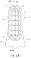
- FIG. 6 A shows a sectional view along the section line AF-AF of FIG. 6 ;
- FIG. 7 shows schematically and in a sectional representation a gas turbine engine on or in which a proposed measuring device is used.
- FIG. 7 illustrates schematically and in a sectional representation a gas turbine engine T, in which the individual engine components are arranged in succession along a rotation axis or central axis M and the engine T is embodied as a turbofan engine.
- air is sucked along an entry direction R using a fan F.
- Said fan F arranged in a fan casing FC, is driven by a rotor shaft RS, which is rotated by a turbine TT of the engine T.
- the Turbine TT is connected to a compressor V, which for example has a low pressure compressor 11 and a high pressure compressor 12 , as well as a medium pressure compressor if necessary.
- the fan F supplies air to the compressor V on the one hand and a secondary current channel or bypass channel B on the other to generate the thrust.
- the bypass channel B is based around a core engine comprising the compressor V and the turbine TT, which comprises a primary power channel for the air supplied to the core engine by the fan F.
- the turbine TT has a high pressure turbine 13 , a medium pressure turbine 14 and a low pressure turbine 15 .
- the turbine TT drives the rotor shaft S and thus the fan F by means of the energy released during combustion in order to generate the necessary thrust via the air extracted into the bypass channel B.
- the outlet A usually comprises a thruster nozzle with a centrally arranged exit cone C.
- FIGS. 1 - 1 A, 2 - 2 A, 3 - 3 A, 4 , 5 and 6 - 6 A show different variants of measuring devices 2 in the form of probes, for example in the form of exhaust gas probes, which can be used on or in the engine T of FIG. 7 .
- Each of said measuring devices 2 has at least one fluid channel 21 with a diamond-shaped cross-section as well as a course by means of which, starting from an inlet 210 of the fluid channel 21 to an outlet 211 of the fluid channel 21 , measuring fluid conveyed in the fluid channel 21 , for example air, is deflected by more than 90°.
- All embodiment variants of FIGS. 1 to 6 A are produced from metal or plastic using an additive production process, for example in a DLD or DMLS process.
- a length l of each fluid channel 21 of the represented embodiment variant is at least 50 mm.
- at least one width b and a height h of the diamond-shaped cross-section each lies in the range of 0.4 mm to 3 mm.
- the measuring device 2 comprises a probe body 20 with an internal, integrated fluid channel 21 that is L-shaped in cross-section.
- the fluid channel 21 comprises three successive sections 21 a , 21 b and 21 c starting from the inlet 210 towards the outlet 211 .
- the two straight, but rotated 90° with respect to each other, channel sections 21 a and 21 c of the fluid channel 21 are joined to each other by a central arc-shaped section 21 b .
- Said arc-shaped channel section 21 b therefore has a bend angle of 90°.
- analysis electronics 3 are assigned to the fluid channel 21 and are configured for the automatic generation of a measurement or analysis signal 30 , which is generated on the basis of the measuring fluid flowing through the fluid channel 21 .
- the analysis electronics 3 are coupled to a sensor provided on or in the fluid channel 21 , for example.
- the fluid channel 21 of the measuring device 2 is formed in the probe body 20 over more than three interconnected channel sections 21 a to 21 c .
- a first channel section 21 a extending in a straight line and connected to the inlet 210 is again oriented at an angle of 90° to an equally straight line channel section 21 e that opens into the outlet 211 .
- Said two channel sections 21 a and 21 e are connected to each other by means of several, in the present case three, channel sections 21 b , 21 c and 21 d .
- Two arc-shaped channel sections 21 b and 21 d are connected to each other by a straight middle channel section 21 c .
- the arc-shaped channel sections 21 b and 21 d each have a bend angle in the region of 45°.
- the probe body 2 has an integrated fluid channel 21 with a Z-shaped course.
- several channel sections 21 a to 21 e are connected to each other along a longitudinal extension direction of the fluid channel 21 .
- Two arc-shaped channel sections 21 b and 21 d are bent in different directions to form the Z-shaped course of the fluid channel 21 .
- the probe body 20 forms a probe head 200 , on which the inlet 210 of the fluid channel 21 is provided.
- the additively manufactured probe body 20 is part of an exhaust gas probe, for example.
- the course of the fluid channel 21 provided here is based on the embodiment variant of FIGS. 2 and 2 A and comprises a plurality of differently curved channel sections 21 b and 21 d joined to each other by a straight channel section 21 c.
- the probe body 20 is L-shaped and integrates within it a Z-shaped fluid channel 21 .
- FIGS. 6 and 6 A show different views of another embodiment variant of a measuring device 2 .
- a probe body 20 of the measuring device forms an L-shaped probe head 200 .
- several L-shaped and parallel fluid channels 21 are provided in the probe body 20 .
- the individual fluid channels 21 are disposed adjacent to each other or one above the other within the probe body 20 along a cross-sectional axis in a spatial direction z.
- the different fluid channels 21 can be provided to determine different measurement data and therefore for the generation of different measurement and analysis signals 30 , 31 and 32 using the analysis electronics 3 .
- the probe head 200 of the embodiment variant of FIGS. 6 and 6 A has a cross-section in which two arc-shaped end sections are connected to each other by a middle section, which is bounded by straight edges. Centrally within this cross-section, which is referred to as elliptical, the fluid channels 21 are provided in a row side by side. A plurality of cooling channels 40 , 41 , 42 and 44 are grouped around said row of fluid channels 21 .
- the cooling channels 40 to 44 comprise different cross-sections from the diamond-shaped cross-section of the fluid channels 21 in the present case, but can in principle also have a diamond-shaped cross-section.
- the cross-sectional areas of the cooling channels 40 to 44 are each a multiple greater than the cross-sectional areas of the fluid channels 21 .
- cooling channels 40 to 44 are grouped around the fluid channels 21 in such a way that each fluid channel 21 is framed by four cooling channels 43 / 44 .
- Four cooling channels 43 / 44 are grouped around a centrally arranged fluid channel 21 , so that the row of fluid channels 21 extends between two rows of cooling channels 43 / 44 .
- a cooling channel arrangement with additional cooling channels 40 / 41 which is circumferentially encircling in the cross-sectional view, is provided around the defined arrangement with the central row of fluid channels and the two rows of cooling channels 43 / 44 .
- the cooling channels 40 / 44 are thus on the one hand in parallel with the row of fluid channels 21 and thus arranged in the spatial direction z.
- several parallel rows of cooling channels 40 / 44 are provided in the spatial direction x and transverse to the spatial direction z.
Landscapes
- Engineering & Computer Science (AREA)
- Physics & Mathematics (AREA)
- General Physics & Mathematics (AREA)
- Chemical & Material Sciences (AREA)
- Combustion & Propulsion (AREA)
- Mechanical Engineering (AREA)
- General Engineering & Computer Science (AREA)
- Manufacturing & Machinery (AREA)
- Fluid Mechanics (AREA)
- Materials Engineering (AREA)
- Measuring Temperature Or Quantity Of Heat (AREA)
Abstract
Description
- 11 Low pressure compressor
- 12 High pressure compressor
- 13 High pressure turbine
- 14 Medium pressure turbine
- 15 Low pressure turbine
- 2 Measuring device
- 20 Probe body
- 200 Probe head
- 21 Fluid channel
- 210 (Channel) inlet
- 211 (Channel) outlet
- 21 a-21 e Channel section
- 3 Analysis electronics
- 30, 31, 32 Signal
- 40-44 Cooling channel
- A Outlet
- B Bypass Channel
- BK Combustion chamber section
- C Outlet cone
- E Inlet/intake
- F Fan
- FC Fan housing
- h Height
- Length
- M Central axis/rotation axis
- R Direction of entry
- RS Rotor shaft
- T Turbofan engine (gas turbine engine)
- TT Turbine
- V Compressor
Claims (17)
Applications Claiming Priority (2)
| Application Number | Priority Date | Filing Date | Title |
|---|---|---|---|
| DE102018112722.7A DE102018112722A1 (en) | 2018-05-28 | 2018-05-28 | Measuring device with at least one fluid channel for the guidance of a measuring fluid |
| DE102018112722.7 | 2018-05-28 |
Publications (2)
| Publication Number | Publication Date |
|---|---|
| US20190360895A1 US20190360895A1 (en) | 2019-11-28 |
| US11549862B2 true US11549862B2 (en) | 2023-01-10 |
Family
ID=68499274
Family Applications (1)
| Application Number | Title | Priority Date | Filing Date |
|---|---|---|---|
| US16/419,523 Active 2041-10-30 US11549862B2 (en) | 2018-05-28 | 2019-05-22 | Measuring device comprising at least one fluid channel for guiding a measurement fluid |
Country Status (2)
| Country | Link |
|---|---|
| US (1) | US11549862B2 (en) |
| DE (1) | DE102018112722A1 (en) |
Citations (6)
| Publication number | Priority date | Publication date | Assignee | Title |
|---|---|---|---|---|
| US20030182998A1 (en) | 2002-03-28 | 2003-10-02 | Koichi Goto | Airflow meter |
| US20090014360A1 (en) * | 2007-04-16 | 2009-01-15 | The General Hospital Corporation D/B/A Massachusetts General Hospital | Systems and methods for particle focusing in microchannels |
| DE102008025869A1 (en) | 2008-05-31 | 2009-12-03 | Mtu Aero Engines Gmbh | Measuring probe and method for producing a measuring probe |
| GB2521048A (en) | 2013-11-06 | 2015-06-10 | Bae Systems Plc | Conduit |
| WO2015181499A1 (en) | 2014-05-27 | 2015-12-03 | Snecma | Measuring comb for measuring parameters of the gases exiting a turbomachine working section |
| US20160318129A1 (en) * | 2015-05-01 | 2016-11-03 | General Electric Company | System and method for multi-laser additive manufacturing |
-
2018
- 2018-05-28 DE DE102018112722.7A patent/DE102018112722A1/en active Pending
-
2019
- 2019-05-22 US US16/419,523 patent/US11549862B2/en active Active
Patent Citations (8)
| Publication number | Priority date | Publication date | Assignee | Title |
|---|---|---|---|---|
| US20030182998A1 (en) | 2002-03-28 | 2003-10-02 | Koichi Goto | Airflow meter |
| DE10245134A1 (en) | 2002-03-28 | 2003-10-09 | Denso Corp | Air flow meter |
| US20090014360A1 (en) * | 2007-04-16 | 2009-01-15 | The General Hospital Corporation D/B/A Massachusetts General Hospital | Systems and methods for particle focusing in microchannels |
| DE102008025869A1 (en) | 2008-05-31 | 2009-12-03 | Mtu Aero Engines Gmbh | Measuring probe and method for producing a measuring probe |
| GB2521048A (en) | 2013-11-06 | 2015-06-10 | Bae Systems Plc | Conduit |
| WO2015181499A1 (en) | 2014-05-27 | 2015-12-03 | Snecma | Measuring comb for measuring parameters of the gases exiting a turbomachine working section |
| US20170191901A1 (en) | 2014-05-27 | 2017-07-06 | Safran Aircraft Engines | Measuring comb for measuring parameters of the gases exiting a turbomachine working section |
| US20160318129A1 (en) * | 2015-05-01 | 2016-11-03 | General Electric Company | System and method for multi-laser additive manufacturing |
Non-Patent Citations (1)
| Title |
|---|
| German Search Report dated Mar. 15, 2019 for counterpart German Patent Application No. DE 10 2018 112 722.7. |
Also Published As
| Publication number | Publication date |
|---|---|
| US20190360895A1 (en) | 2019-11-28 |
| DE102018112722A1 (en) | 2019-11-28 |
Similar Documents
| Publication | Publication Date | Title |
|---|---|---|
| US20140182292A1 (en) | Integral instrumentation in additively manufactured components of gas turbine engines | |
| KR20130086288A (en) | Device for multipoint acquisition/distribution of fluid, in particular probe for tapping pressure in a turbomachine air inlet | |
| US11650018B2 (en) | Duct mounted heat exchanger | |
| EP3460190A1 (en) | Heat transfer enhancement structures on in-line ribs of an aerofoil cavity of a gas turbine | |
| US20200256887A1 (en) | Total Pressure and Total Temperature Measurement in a Turbomachine | |
| US10371000B1 (en) | Flush-mount combined static pressure and temperature probe | |
| US20160169000A1 (en) | Heat transfer pedestals with flow guide features | |
| US20160047251A1 (en) | Cooling hole having unique meter portion | |
| EP3904641A1 (en) | Variable area turbine vane row assembly | |
| US10697307B2 (en) | Hybrid cooling schemes for airfoils of gas turbine engines | |
| JPH01315623A (en) | Heat exchanger | |
| US20200149401A1 (en) | Airfoil with arced baffle | |
| US11549862B2 (en) | Measuring device comprising at least one fluid channel for guiding a measurement fluid | |
| US11480475B2 (en) | Method and system for measuring temperature in a gas turbine engine | |
| EP3712388B1 (en) | Apparatus and method and system for inspecting a component of a gas turbine engine | |
| US9116051B2 (en) | Actively cooled gas turbine sensor probe housing | |
| US20160230566A1 (en) | Angled pedestals for cooling channels | |
| US10273808B2 (en) | Low loss airflow port | |
| US10619489B2 (en) | Airfoil having end wall contoured pedestals | |
| EP3470629A1 (en) | Film cooling hole arrangement for gas turbine engine component | |
| US20210215063A1 (en) | Turbine blade tip dirt removal feature | |
| EP3754315B1 (en) | ENGINE INTAKE PRESSURE AND TEMPERATURE SENSOR PERFORMANCE IMPROVEMENT | |
| EP2904232B1 (en) | Sensor adapter | |
| EP3385501B1 (en) | Coated panel for a gas turbine engine and corresponding gas turbine engine | |
| CN114514360A (en) | Ejector for a high-pressure turbine |
Legal Events
| Date | Code | Title | Description |
|---|---|---|---|
| AS | Assignment |
Owner name: ROLLS-ROYCE DEUTSCHLAND LTD & CO KG, GERMANY Free format text: ASSIGNMENT OF ASSIGNORS INTEREST;ASSIGNORS:CLEMEN, CARSTEN;GERENDAS, MIKLOS;REEL/FRAME:049255/0596 Effective date: 20180612 |
|
| FEPP | Fee payment procedure |
Free format text: ENTITY STATUS SET TO UNDISCOUNTED (ORIGINAL EVENT CODE: BIG.); ENTITY STATUS OF PATENT OWNER: LARGE ENTITY |
|
| STPP | Information on status: patent application and granting procedure in general |
Free format text: DOCKETED NEW CASE - READY FOR EXAMINATION |
|
| STPP | Information on status: patent application and granting procedure in general |
Free format text: NON FINAL ACTION MAILED |
|
| STPP | Information on status: patent application and granting procedure in general |
Free format text: RESPONSE TO NON-FINAL OFFICE ACTION ENTERED AND FORWARDED TO EXAMINER |
|
| STPP | Information on status: patent application and granting procedure in general |
Free format text: NOTICE OF ALLOWANCE MAILED -- APPLICATION RECEIVED IN OFFICE OF PUBLICATIONS |
|
| STPP | Information on status: patent application and granting procedure in general |
Free format text: PUBLICATIONS -- ISSUE FEE PAYMENT VERIFIED |
|
| STCF | Information on status: patent grant |
Free format text: PATENTED CASE |