US1154685A - Convertible chair and bed. - Google Patents
Convertible chair and bed. Download PDFInfo
- Publication number
- US1154685A US1154685A US83804414A US1914838044A US1154685A US 1154685 A US1154685 A US 1154685A US 83804414 A US83804414 A US 83804414A US 1914838044 A US1914838044 A US 1914838044A US 1154685 A US1154685 A US 1154685A
- Authority
- US
- United States
- Prior art keywords
- bed
- chair
- support
- spring
- rack
- Prior art date
- Legal status (The legal status is an assumption and is not a legal conclusion. Google has not performed a legal analysis and makes no representation as to the accuracy of the status listed.)
- Expired - Lifetime
Links
- 230000008093 supporting effect Effects 0.000 description 14
- 238000010276 construction Methods 0.000 description 3
- 208000010543 22q11.2 deletion syndrome Diseases 0.000 description 1
- 241001199012 Usta Species 0.000 description 1
- 230000015572 biosynthetic process Effects 0.000 description 1
- 230000000284 resting effect Effects 0.000 description 1
Images

Classifications
-
- B—PERFORMING OPERATIONS; TRANSPORTING
- B60—VEHICLES IN GENERAL
- B60N—SEATS SPECIALLY ADAPTED FOR VEHICLES; VEHICLE PASSENGER ACCOMMODATION NOT OTHERWISE PROVIDED FOR
- B60N2/00—Seats specially adapted for vehicles; Arrangement or mounting of seats in vehicles
- B60N2/75—Arm-rests
- B60N2/753—Arm-rests movable to an inoperative position
Definitions
- the present invention relates to an improvement in combined easy chair and bed and more particularly to a device'wherein the back' is adjustable to an inclinedposition or may lie in a'pl'ane'par'allel to the plane of the seat.
- the invention has for its principal object's'to 'pro'vide' a"struct ure wherein the chair side arms'are employed in forming the bed; one in which the chair back is supported from beingoverba'la'nced when in horizontal position by the weight of the user, and one provided with a simple means for readily adjusting the chair backand for also *operating 'the support for the same when in afhorizontal position.
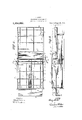
- Figure '1 is a viewin side elevation of an embodiment illustrating my invention disclosing theadjustable back in inclined position in dotted lines'and in full lines the device in the 'formof a bed.
- Fig. 2 is a top plan viewof the device inthe form of a bed, disclosing the position of the" side arms when the deviiceisusedasa"bed',"and in dotted lines, the upholstery.
- Fig. 3 is a longitudinal sectional view,” disclosing more fully the operating means for the adj usta'ble' back and the support;- Fig.4 is'a "sectional view on line 4"-l :ofi Fig. 2, vdisclosin'g'the struc ture for operatingithe adjustable backand Specification of Letters Patent.
- Fig. 5 is a view in detail of one of the rack locking springs.
- the numeral 1 designates a suitable support forming base consisting of the side members 2 and end members 3 which are connected at their ends and which carry the spring supporting frame consisting of the members 4, the construction forming a suitable seat frame upholstered in any suitable manner, as at l, and provided with casters e 7
- a suitable back frame consisting of the side members 5 and end members 6 is'connected at one end by the hinges 7 to the rear of the seat frame at a point approximately in line with members 4: of the spring sup porting frame, and said back carries a springsupporting frame consisting of the member 4 and is upholstered in any suitable m'anner, as at 7 I
- Suitable side arms 8 and 9 are positione on the upper edge of the side members 2 of the seat frame and the same carry on their lower edge suitabledowels 10 which project into slots or openings 11 formed in the upl per edge of the side members and said arms are forced rearwardly in contact with the back when the same
- rack bars 14 pivotally connected at one end by a rack link 15 with the side members of the-chair back.
- Suitable spring catches 21 and 22 are adapted to cooperate with the teeth of the rack bars 14 when the cogs 16 are disengaged-therefrom and retain the back in its adjusted position.
- the catch 21 is carried by a spring 23 mounted in a recess in the side 2 of the frame and is adapted to be car-.
- the catch 22 is carried by a bowed spring member 24 pivoted, as at 25, in a recess in the opposite side 2 of the frame, and the lowerend of said member 2% is forced outwardly by a spring 26 so it will be apparent that when the spring 18 operates the shaft 17 and disconnects the cog 16 from the rack bar 14,
- spring frame 4 One end'of the receptacle is provided with suitable'casters 30 and the same when in its extended position provides a support for the back when in its lowered position and also prevents the bed from becoming overbalanced by its occupant. If desirable,the bed clothing, when not in use, may be deposited in the receptacle 28.
- a foot rest 81 is pivotally mount-ed on a bracket 32 carried by the forward end of a support 33 which is slidably mounted between guides 84.- which extend to a point adjacent an opening 35 in the front end wall 3, of the supporting base, and through which said support operates.
- a closure 36 carried by said support beneath the foot rest is adapted to close the opening 35 when'the rest is not in use.
- the chair is employed as a bed
- the handle 19 is positioned, as'in Fig. 2, and is operated'in a counter-clock-wise direction, which will cause the cogs 16 and 16 to-engage with the racks 27 on the receptacle and .move the same outwardly in a position to assistin supporting the chair back when lowered.
- the handle is now swung to the opposite direction with the cam portion 20 resting on the outer surface of the side member 2 and pressure being applied to the end of the handle will cause the cogs to cause the back to be gradually lowered over the receptacle.
- the arms 8 and 9 are removed from their respective places and the up between the rear of the supporting base and the forward end of the back and the arm 9 is positioned with its upholstered side up on the foot rest with the dowels 10 inserted in openings '37 in the front end member 3.
- a supporting base forming a seatframe, a cushion for said frame, a back hinged at its lower end to said supporting base and capable of being. adjusted to a plane parallel therewith, a cushion for said back, said back cushion adapted when said back is in a substantially vertical position to overlie the rear edge of said seat cushion, a pair of cushion members detachably carried by said V arm 8 is positioned with its upholstered side supporting base and forming chair arms,
- said arms adapted when said back is adjust ed to a position approximately parallel with the seat for' positioning one between the seat cushion and the back cushion and one at the forward edge of the seat cushion for providing a-continuous cushion bed surface.
- a supporting base forming a chair seat, a chair back hinged at its lower end to said supporting base and capable of being adjusted. to a plane parallel thereto, a support for telescoping beneath said chair seat and capable of movement beneath said back when the same is in its last mentioned position,-a rack carried by said chair back, a rack carried by said support, said racks being arranged one above the other in different vertical planes and with their teeth disposed toward each other, and a suitable rotatably mounted gear for engaging, either of said, racks for operating respectively said hinged back and said support. independently of .each other. 7
Landscapes
- Engineering & Computer Science (AREA)
- Aviation & Aerospace Engineering (AREA)
- Transportation (AREA)
- Mechanical Engineering (AREA)
- Chairs For Special Purposes, Such As Reclining Chairs (AREA)
Description
H. BITTEL.
CONVERTIBLE CHAIR AND BED.
APPLICATION 111.50 MAY 12. 1914.
Patented Sept. 28, 1915.
2 SHEETS-SHEET 1.
W/ T/VESSES:
H. BITTEL.
CONVERTIBLE CHAIR AND BED.
APPLICATION FILED MAYIZ. :914. 1 154 65 PatentedSept. 28, 1915.
9 9 2 SHEETS-SHEET 2.
WITNESSES:
' er e rs e i r cri es HENRY BITTEL, OF SAN FRANCISCO, CALIFORNIA.
CONVERTIBLE CHAIR AND BED.
To all whom it may concern Be it known that I; HENRY BITTnL, a citizen of the United States, residing in the city and county of San Francisco and State of califor'niafhave invented-certain new and useful Improvements in Convertible Chairs and Beds, of 'which the following is a specification.
The present invention relates to an improvement in combined easy chair and bed and more particularly to a device'wherein the back' is adjustable to an inclinedposition or may lie in a'pl'ane'par'allel to the plane of the seat.
' The invention has for its principal object's'to 'pro'vide' a"struct ure wherein the chair side arms'are employed in forming the bed; one in which the chair back is supported from beingoverba'la'nced when in horizontal position by the weight of the user, and one provided with a simple means for readily adjusting the chair backand for also *operating 'the support for the same when in afhorizontal position.
*Nith' the above'mentionednnd other objects in view, the device consists in the novel construction andcombination' of parts hereinafter described, illustrated in the accompanying drawings and pointed out in the claims hereto appended; it being understood th'atva'rious changesin the form, proportion, sizeand'minor details of construction Within the scopeof the appendedclaims may be resorted to without' departing from the spirit or sacrificing any ofthe-advantages of the inventionfl m To' more fully comprehend the invention reference should: be had' to the accompany in'g drawings, 'wherein:''
"Figure '1 is a viewin side elevation of an embodiment illustrating my invention disclosing theadjustable back in inclined position in dotted lines'and in full lines the device in the 'formof a bed. Fig. 2 isa top plan viewof the device inthe form of a bed, disclosing the position of the" side arms when the deviiceisusedasa"bed',"and in dotted lines, the upholstery. Fig. 3 is a longitudinal sectional view," disclosing more fully the operating means for the adj usta'ble' back and the support;- Fig.4 is'a "sectional view on line 4"-l :ofi Fig. 2, vdisclosin'g'the struc ture for operatingithe adjustable backand Specification of Letters Patent.
Application filed May 12, 1914. SerialNo. 838,044.
support therefor. Fig. 5 is a view in detail of one of the rack locking springs.
Referring more particularly to the drawings, wherein like characters of reference designate corresponding parts throughout the several views, the numeral 1 designates a suitable support forming base consisting of the side members 2 and end members 3 which are connected at their ends and which carry the spring supporting frame consisting of the members 4, the construction forming a suitable seat frame upholstered in any suitable manner, as at l, and provided with casters e 7 A suitable back frame consisting of the side members 5 and end members 6 is'connected at one end by the hinges 7 to the rear of the seat frame at a point approximately in line with members 4: of the spring sup porting frame, and said back carries a springsupporting frame consisting of the member 4 and is upholstered in any suitable m'anner, as at 7 I Suitable side arms 8 and 9 are positione on the upper edge of the side members 2 of the seat frame and the same carry on their lower edge suitabledowels 10 which project into slots or openings 11 formed in the upl per edge of the side members and said arms are forced rearwardly in contact with the back when the same is slightly inclined by springs 12, positioned in the slots 11. The
side arms'a're upholstered to correspond with the uph'olstering on the seat and back and to bring the surface thereof level with the 'surface of'theseat and back when the arms are employed in connection. therewith in the formation of a bed.
Slidably mounted in guides 13 carried by theside members3 are rack bars 14 pivotally connected at one end by a rack link 15 with the side members of the-chair back. The rack bars li-are operated to raise and lower the chair back by suitable cogs 16 and l6 mounted to rotate with a shaft 17 extending transversely of the rear portion of the supporting base and 'slidablysmounted in the side members 2 thereof "A springlS coiled about theshaft 17 forces the same and the cogs carried thereby in one direction and a handle 19 pivoted tothe opposite end of the shaft and formed with a cam surface 20 thereon which is adapted to be forced into contact withone of the side members of the supporting base assists, when pressure is applied thereto, in drawing the shaft in the opposite direction against the tension of the spring 18.
ried into intermeshing engagement with one of the rack bars 14 by the pressure of said spring when the cog 16 is moved therefromby the pressure of the spring 18. The catch 22 is carried by a bowed spring member 24 pivoted, as at 25, in a recess in the opposite side 2 of the frame, and the lowerend of said member 2% is forced outwardly by a spring 26 so it will be apparent that when the spring 18 operates the shaft 17 and disconnects the cog 16 from the rack bar 14,
, spring frame 4. One end'of the receptacle is provided with suitable'casters 30 and the same when in its extended position provides a support for the back when in its lowered position and also prevents the bed from becoming overbalanced by its occupant. If desirable,the bed clothing, when not in use, may be deposited in the receptacle 28.
A foot rest 81 is pivotally mount-ed on a bracket 32 carried by the forward end of a support 33 which is slidably mounted between guides 84.- which extend to a point adjacent an opening 35 in the front end wall 3, of the supporting base, and through which said support operates. A closure 36 carried by said support beneath the foot rest is adapted to close the opening 35 when'the rest is not in use.
lVhen the chair is employed as a bed, the handle 19 is positioned, as'in Fig. 2, and is operated'in a counter-clock-wise direction, which will cause the cogs 16 and 16 to-engage with the racks 27 on the receptacle and .move the same outwardly in a position to assistin supporting the chair back when lowered. The handle is now swung to the opposite direction with the cam portion 20 resting on the outer surface of the side member 2 and pressure being applied to the end of the handle will cause the cogs to cause the back to be gradually lowered over the receptacle. The arms 8 and 9 are removed from their respective places and the up between the rear of the supporting base and the forward end of the back and the arm 9 is positioned with its upholstered side up on the foot rest with the dowels 10 inserted in openings '37 in the front end member 3. i
It will be apparent that I have provided a chair which is capable of being rapidly and easily converted into a bed; one which when converted into a bed is prevented from becoming overbalanced, and one in which the operatingv of the back and the moving of the receptacle is accomplished by a single mechanism.
Having thus described my invention what I claim as new and desire to protect by Letters Patent is 1. In a device of the class described, a supporting base forming a seatframe, a cushion for said frame, a back hinged at its lower end to said supporting base and capable of being. adjusted to a plane parallel therewith,a cushion for said back, said back cushion adapted when said back is in a substantially vertical position to overlie the rear edge of said seat cushion, a pair of cushion members detachably carried by said V arm 8 is positioned with its upholstered side supporting base and forming chair arms,
said arms adapted when said back is adjust ed to a position approximately parallel with the seat for' positioning one between the seat cushion and the back cushion and one at the forward edge of the seat cushion for providing a-continuous cushion bed surface.
2. In a device of'the class described, a supporting base forming a chair seat, a chair back hinged at its lower end to said supporting base and capable of being adjusted. to a plane parallel thereto, a support for telescoping beneath said chair seat and capable of movement beneath said back when the same is in its last mentioned position,-a rack carried by said chair back, a rack carried by said support, said racks being arranged one above the other in different vertical planes and with their teeth disposed toward each other, and a suitable rotatably mounted gear for engaging, either of said, racks for operating respectively said hinged back and said support. independently of .each other. 7
3. In a device of the class described, a
supporting base forming a chair seat, a
chair backhinged at its lower end. to said supporting base and capable of being ad justed to a plane parallel thereto, a support for telescoping beneath said chair seat and capable of movement beneath said back when the same is in its last mentioned position, a rack carried by said chair back, a rack carried by said support, said racks being arranged one above the other in difierent vertical planes and with their teeth disposed toward each other, a suitable rotatably mounted gear for engaging either of said racks for operating respectively said hinged back and said support independently of each other, and a spring locking member releasable on the movement of said shiftable gear into engagement with the rack on said support for engaging the rack associated with said chair back to lock the same 15 HENRY BITTEL.
Witnesses HARRY A. ToT'rEN, D. B. RICHARDS.
Copies of this patent may be obtained for five cents each, by addressing the Commissioner of Patents, Washington, D. G.
Priority Applications (1)
| Application Number | Priority Date | Filing Date | Title |
|---|---|---|---|
| US83804414A US1154685A (en) | 1914-05-12 | 1914-05-12 | Convertible chair and bed. |
Applications Claiming Priority (1)
| Application Number | Priority Date | Filing Date | Title |
|---|---|---|---|
| US83804414A US1154685A (en) | 1914-05-12 | 1914-05-12 | Convertible chair and bed. |
Publications (1)
| Publication Number | Publication Date |
|---|---|
| US1154685A true US1154685A (en) | 1915-09-28 |
Family
ID=3222749
Family Applications (1)
| Application Number | Title | Priority Date | Filing Date |
|---|---|---|---|
| US83804414A Expired - Lifetime US1154685A (en) | 1914-05-12 | 1914-05-12 | Convertible chair and bed. |
Country Status (1)
| Country | Link |
|---|---|
| US (1) | US1154685A (en) |
-
1914
- 1914-05-12 US US83804414A patent/US1154685A/en not_active Expired - Lifetime
Similar Documents
| Publication | Publication Date | Title |
|---|---|---|
| US287789A (en) | arbog-ast | |
| US1154685A (en) | Convertible chair and bed. | |
| US375471A (en) | Chair-back and head-rest | |
| US847332A (en) | Adjustable chair. | |
| US1125167A (en) | Adjustable chair. | |
| US1243887A (en) | Adjustable bed-spring for beds, davenports, couches, and the like. | |
| US607538A (en) | Combined chair and bed | |
| US795535A (en) | Reclining-chair. | |
| US676788A (en) | Chair. | |
| US296931A (en) | Combined platform-rocker and reclining-chair | |
| US715388A (en) | Reclining-chair. | |
| US778074A (en) | Foot-rest for chairs. | |
| US576480A (en) | Chair | |
| US360279A (en) | Surgical chair | |
| US741121A (en) | Reclining-chair. | |
| US2467638A (en) | Convertible seat structure | |
| US1030876A (en) | Desk-stool. | |
| US1189705A (en) | Foot-rest for chairs. | |
| US883446A (en) | Chair. | |
| US579499A (en) | shapira | |
| US482745A (en) | Chair | |
| US140868A (en) | Improvement in invalid-chairs | |
| US261205A (en) | Joseph ohampie | |
| US348173A (en) | Adjustable chair | |
| US329272A (en) | cameron |