US11518502B2 - Energy absorption stabilizers and methods - Google Patents
Energy absorption stabilizers and methods Download PDFInfo
- Publication number
- US11518502B2 US11518502B2 US16/399,932 US201916399932A US11518502B2 US 11518502 B2 US11518502 B2 US 11518502B2 US 201916399932 A US201916399932 A US 201916399932A US 11518502 B2 US11518502 B2 US 11518502B2
- Authority
- US
- United States
- Prior art keywords
- stabilizer
- retractable section
- plates
- energy absorbing
- retractable
- Prior art date
- Legal status (The legal status is an assumption and is not a legal conclusion. Google has not performed a legal analysis and makes no representation as to the accuracy of the status listed.)
- Active, expires
Links
- 239000003381 stabilizer Substances 0.000 title claims abstract description 147
- 238000000034 method Methods 0.000 title claims description 34
- 238000010521 absorption reaction Methods 0.000 title claims description 27
- 238000006073 displacement reaction Methods 0.000 claims abstract description 24
- 230000007246 mechanism Effects 0.000 claims description 14
- 239000000463 material Substances 0.000 claims description 7
- 239000004033 plastic Substances 0.000 claims description 5
- 229920003023 plastic Polymers 0.000 claims description 5
- 230000004044 response Effects 0.000 claims description 5
- 238000010276 construction Methods 0.000 description 7
- 230000008901 benefit Effects 0.000 description 5
- 239000002131 composite material Substances 0.000 description 5
- 238000012360 testing method Methods 0.000 description 5
- 229910001092 metal group alloy Inorganic materials 0.000 description 4
- 238000013461 design Methods 0.000 description 3
- 238000011156 evaluation Methods 0.000 description 3
- 229910052751 metal Inorganic materials 0.000 description 3
- 239000002184 metal Substances 0.000 description 3
- 229910000838 Al alloy Inorganic materials 0.000 description 2
- 230000008878 coupling Effects 0.000 description 2
- 238000010168 coupling process Methods 0.000 description 2
- 238000005859 coupling reaction Methods 0.000 description 2
- 230000008030 elimination Effects 0.000 description 2
- 238000003379 elimination reaction Methods 0.000 description 2
- 239000004744 fabric Substances 0.000 description 2
- 238000012986 modification Methods 0.000 description 2
- 230000004048 modification Effects 0.000 description 2
- 230000008569 process Effects 0.000 description 2
- RZVHIXYEVGDQDX-UHFFFAOYSA-N 9,10-anthraquinone Chemical compound C1=CC=C2C(=O)C3=CC=CC=C3C(=O)C2=C1 RZVHIXYEVGDQDX-UHFFFAOYSA-N 0.000 description 1
- 229920002430 Fibre-reinforced plastic Polymers 0.000 description 1
- 229910001069 Ti alloy Inorganic materials 0.000 description 1
- ATJFFYVFTNAWJD-UHFFFAOYSA-N Tin Chemical compound [Sn] ATJFFYVFTNAWJD-UHFFFAOYSA-N 0.000 description 1
- XAGFODPZIPBFFR-UHFFFAOYSA-N aluminium Chemical compound [Al] XAGFODPZIPBFFR-UHFFFAOYSA-N 0.000 description 1
- 230000006835 compression Effects 0.000 description 1
- 238000007906 compression Methods 0.000 description 1
- 239000011162 core material Substances 0.000 description 1
- 238000011161 development Methods 0.000 description 1
- 239000000835 fiber Substances 0.000 description 1
- 239000011151 fibre-reinforced plastic Substances 0.000 description 1
- 239000011152 fibreglass Substances 0.000 description 1
- 239000012530 fluid Substances 0.000 description 1
- 239000006260 foam Substances 0.000 description 1
- 239000003365 glass fiber Substances 0.000 description 1
- 239000003562 lightweight material Substances 0.000 description 1
- 230000008520 organization Effects 0.000 description 1
- 238000011160 research Methods 0.000 description 1
- 239000002689 soil Substances 0.000 description 1
Images


Classifications
-
- B—PERFORMING OPERATIONS; TRANSPORTING
- B64—AIRCRAFT; AVIATION; COSMONAUTICS
- B64C—AEROPLANES; HELICOPTERS
- B64C25/00—Alighting gear
- B64C25/32—Alighting gear characterised by elements which contact the ground or similar surface
-
- B—PERFORMING OPERATIONS; TRANSPORTING
- B64—AIRCRAFT; AVIATION; COSMONAUTICS
- B64C—AEROPLANES; HELICOPTERS
- B64C25/00—Alighting gear
- B64C25/32—Alighting gear characterised by elements which contact the ground or similar surface
- B64C25/58—Arrangements or adaptations of shock-absorbers or springs
-
- B—PERFORMING OPERATIONS; TRANSPORTING
- B64—AIRCRAFT; AVIATION; COSMONAUTICS
- B64C—AEROPLANES; HELICOPTERS
- B64C5/00—Stabilising surfaces
- B64C5/10—Stabilising surfaces adjustable
- B64C5/12—Stabilising surfaces adjustable for retraction against or within fuselage or nacelle
-
- B—PERFORMING OPERATIONS; TRANSPORTING
- B64—AIRCRAFT; AVIATION; COSMONAUTICS
- B64C—AEROPLANES; HELICOPTERS
- B64C25/00—Alighting gear
- B64C25/32—Alighting gear characterised by elements which contact the ground or similar surface
- B64C2025/325—Alighting gear characterised by elements which contact the ground or similar surface specially adapted for helicopters
-
- B—PERFORMING OPERATIONS; TRANSPORTING
- B64—AIRCRAFT; AVIATION; COSMONAUTICS
- B64C—AEROPLANES; HELICOPTERS
- B64C27/00—Rotorcraft; Rotors peculiar thereto
- B64C27/04—Helicopters
Definitions
- a tail skid For landing an aircraft, such as a rotorcraft (i.e., helicopter), a tail skid is attached to a distal end of a stabilizer (i.e., vertical tail tin or horizontal stabilizer) to minimize and/or prevent damage to the rotorcraft when the stabilizer contacts the ground.
- a stabilizer i.e., vertical tail tin or horizontal stabilizer
- a tail skid deforms and absorbs the energy generated.
- impact load induced by a tail landing on the tail boom airframe structure of the aircraft may be reduced.
- tail skids are made of a circular tube design that are bolted on stabilizers and are formed from metal alloys. Such tail skids require their own support structure independent of the stabilizer, which often increases stabilizer weight requirements. Also, to adequately provide for sufficient ground clearance, the inclusion of a tail skid further contributes to limitations for the dimensions and aerodynamic performance of the stabilizer.
- a stabilizer of an aircraft includes an energy absorbing assembly.
- the energy absorbing assembly includes first and second portions and a retractable section.
- the retractable section may be at least partially affixed to the first portion and is configured to enable displacement of the second portion of the stabilizer with respect to the first portion.
- a method of energy absorption by a stabilizer includes setting, in a first positioning, first and second portions of the stabilizer. In the first positioning, the first and second portions are encased in an outer skin, separated by an air gap, and adjoined by a retractable section. Also, in response to an impact event, the method includes engaging a retractable section of the stabilizer to resistively displace the second portion to converge the first portion over the air gap.
- a method of energy absorption by a stabilizer includes forming a first portion of the stabilizer. The method further includes forming a retractable section that is at least partially affixed to the first portion. Also, the retractable system may be configured to enable displacement of a second portion of the stabilizer with respect to the first portion.
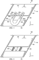
- FIGS. 1 A and 1 B illustrate cross-sectional top views of an energy absorbing assembly in accordance with implementations of various techniques described herein.
- FIG. 2 is a particular illustrative aspect of methods in accordance with implementations of various techniques described herein.
- FIG. 3 illustrates a cut-away perspective of an energy absorbing assembly in accordance with implementations of various techniques described herein.
- FIG. 4 illustrates a cross-sectional top view of an energy absorbing assembly in accordance with implementations of various techniques described herein.
- FIG. 5 illustrates a cross-sectional top view of an energy absorbing assembly in accordance with implementations of various techniques described herein.
- FIG. 6 illustrates a cross-sectional top view of an energy absorbing assembly in accordance with implementations of various techniques described herein.
- FIG. 7 is a particular illustrative aspect of methods in accordance with implementations of various techniques described herein.
- Example embodiments of the present disclosure allow for energy from an impact to be absorbed by the stabilizer itself through either elastic or plastic deformation, such that either minimal or no damage may be transferred to the tail boom/airframe structure of the aircraft.
- energy absorption capabilities can be provided within the sleek airfoil design (i.e., aerodynamic shape) of the stabilizer itself that is already optimized for peak aerodynamic performance (e.g., to stabilize the aircraft, and to minimize drag and provide lift).
- the stabilizers and methods described herein further allow for different stabilizer energy absorption levels by adjusting the amount of admissible friction that can be introduced.
- the stabilizers and methods described herein promote greater ease in flight test collection, promote lower cost and less weight by reducing part counts via the elimination, and allow for increases in stabilizer aerodynamic surface dimensions.
- FIGS. 1 A- 1 B cross-sectional top-views of an energy absorbing assembly (i.e., an energy absorbing system, an energy absorbing section, an assembly) 110 of a stabilizer 100 for an aircraft is shown in a first positioning ( FIG. 1 A ) and a second positioning ( FIG. 1 B ).
- the stabilizer 100 may be a vertical stabilizer (i.e., a fin, a tail fin, a vertical plank) or a horizontal stabilizer (i.e., a horizontal fin, a horizontal plank) of the aircraft.
- FIG. 1 A illustrates the energy absorbing assembly 110 of the stabilizer 100 in the first positioning (i.e., prior to an impact event), while FIG.
- the energy absorbing assembly 110 may include a first portion 122 (e.g. an upper portion), a second portion (e.g., a lower portion) 124 , and a retractable section 130 (i.e., a resettable section) (e.g., a mechanical retractable section).
- the retractable section 130 may be at least partially affixed to the first portion 122 and is configured to enable displacement of the second portion 124 of the stabilizer 100 with respect to the first portion 122 .
- the first and second portions 122 , 124 may be made of the same rigid material(s) as that of the rest of the stabilizer 100 itself that is optimized for predefined aerodynamic load requirements.
- first and second portions 122 , 124 may be distinct regions of the stabilizer 100 that may be either contiguous to, or alternatively, coupled to the stabilizer 100 .
- the first and second portions 122 , 124 may be part of the airfoil itself, and have aerodynamic loading such that the portions 122 , 124 are able to provide aerodynamic lift (i.e., the force that is perpendicular to the oncoming air-flow).
- the first and second portions 122 , 124 may be made of any light-weight but rigid composite core material (e.g., fiber-reinforced plastics (e.g., tailored glass fiber, fiberglass, foams) and/or a thin metal (e.g., a metal alloy such as an aluminum or titanium alloy) etc. that can be substantially the same as the other regions of the stabilizer.
- the second portion may be configured to either elastically or plastically deform.
- the stabilizer 100 may further include an outer skin 140 (i.e., a shell, a wrapper, a composite skin) that fully encloses the first and second portions 122 , 124 and the retractable section 130 .
- an outer skin 140 i.e., a shell, a wrapper, a composite skin
- FIGS. 1 A- 1 B are cross-sectional views, the outer skin 140 is shown only on the outer edges of the energy absorbing assembly 110 . Nevertheless, in a full depiction, the outer skin 140 may fully surround at least the energy absorbing assembly 110 of the stabilizer 100 and provide one or more aerodynamic surfaces of the aerodynamics shape of the airfoil. Hence, the outer skin 140 may facilitate the requisite aerodynamic performance (such as to minimize drag and increase lift).
- the outer skin 140 may be made from any rigid, light-weight material including a fabric (e.g., fabric layers, composite fibers) or a thin metal (e.g., a metal alloy such as an aluminum alloy) etc. As shown in FIG. 1 B , in some cases upon an impact event, the outer skin 140 would collapse on itself or detach (e.g., “fall-off”) from the energy absorbing assembly 110 including the first and second portions 122 , 124 and the retractable section 130 .
- a fabric e.g., fabric layers, composite fibers
- a thin metal e.g., a metal alloy such as an aluminum alloy
- the stabilizer 100 may further include an air gap 150 located between the first and second portions 122 , 124 , and proximate to the retractable section 130 .
- the air gap 150 may be fully enclosed by the outer skin 140 .
- the second portion 124 may be compressed over the air gap 150 such that the second portion 124 displaces toward the first portion 122 .
- the displacement of the second portion 124 may be one of linear displacement, axial displacement, or angular displacement with relation to the first portion 122 .
- the retractable section 130 may include one or more plates 132 (e.g., rigid metal or rigid composite plastic plates) that are at least partially adjoined to the first portion 122 of the energy absorbing assembly 100 .
- the one or more plates 132 may be configured to align the displacement of the second section 120 in the direction of the first portion 110 .
- the one or more plates 132 may have a greater length (L) than that of the width (W) of the one or more plates 132 .
- each of the one or more plates 132 may include a respective aperture 180 (i.e., a narrow aperture, slot, groove, orifice, a through circumferentially enclosed opening).
- the respective aperture(s) 180 may be of a similar shape and extend along an interior portion of the one or more plates 132 . Moreover, in such examples, the respective aperture(s) 180 may be constructed such that, in the first positioning (as shown in FIG. 1 A ), the aperture(s) may extend upon the one or more plates 132 over the overlapping area of the air gap 150 , but not over the intersection of the one of more plates 132 and the second portion 124 .
- such a construction allows for the most surface area of contact and coupling between the lower end 134 (e.g., below the respective apertures 180 in the longitudinal Y-axis) of the one or more plates 132 and the second portion 124 . Hence, upon an occurrence of an impact event, the normal force that is enacted upon the second portion 124 would be significantly translated to the one or more plates 132 .
- the lower end 134 (e.g., below the respective apertures 180 in the longitudinal Y-axis) of the one or more plates 132 may be retractable extension plate portions of the one or more plates 132 in such an implementation, the retractable extension plate portions 134 may be configured to resistively “slide” (via kinetic friction) into respective upper portions 133 of the one or more plates 132 . As such, the extension plate portions may allow for ease in resetting the retractable portion 130 back to a first positioning.
- the retractable section may further include a fastener 135 (i.e., a threaded fastener, a bolt, a screw, a pin, etc.) and an associated lock washer (or nut) (not shown).
- a fastener 135 i.e., a threaded fastener, a bolt, a screw, a pin, etc.
- an associated lock washer or nut
- the fastener 135 and the associated washer (or nut) e.g., lock washers, locknuts, jam nuts, etc.
- a first end 133 e.g., an upper end
- a diameter of the fastener 135 may be greater than a width of an associated aperture 180 .
- a greater kinetic frictional force i.e., resistive force of friction
- resistive force of friction i.e., resistive force of friction
- different diameter sizes of the fastener 135 may be employed so as to generate different coefficients of friction between the fastener 135 and the associated aperture 180 ; thus, resulting in different magnitudes of kinetic frictional force.
- one or more brackets may be used to affix the one or more plates 132 of the retractable section 130 to the first and second portions 122 , 124 .
- the one or more plates 132 may include one or more notches (not shown) at equidistant intervals along the aperture 180 .
- energy absorption metrics i.e., levels, values
- the energy absorbing assembly 110 may be customized through the capacity to vary admissible magnitudes of force from an impact (e.g., the kinetic force of friction (i.e., sliding friction) within the retractable section 130 .
- energy absorption metrics may be calibrated in increments directly on the one or more plates 132 that correspond to different respective magnitudes of sliding friction.
- FIGS. 1 A- 1 B illustrate the one or more plates 132 (as well as the aperture(s) 180 and the fastener(s) 135 ) as adjoined on outer sides of the first and second portions 122 , 124
- the one or more plates 132 may be adjoined on inner sides of the first and second portions 122 , 124 .
- the one or more plates 132 may be adjoined such that the one or more plates 132 (as well as the aperture(s) 180 and the fastener(s) 135 ) and the first and second portions 122 , 124 are coplanar on the Z-axis.
- an additional advantage is that the stabilizer 100 can maintain an optimally sleek and precise aerodynamic shape as per build requirements.
- the one or more plates 132 may be diagonally-positioned (i.e., having a particular slope) with reference to a plane on the X-axis and Y-axis.
- particular angles of orientation corresponding to the angle formed between the length (L) of the one or more plates 132 and the width (W) of the first and/or second portions 122 , 124 may be less than 90°.
- such an angle of orientation may allow for greater amounts of energy from impact to be received and absorbed by the retractable section 130 (in comparison to a 90° angle of orientation).
- the one or more plates 132 may be positioned according to other angles of orientation where the angle formed between the length (L) of the one or more plates 132 and the width (W) of the first and/or second portions 122 , 124 may be substantially equal to 90°, or greater than 90°.
- the one or more plates 132 may be diagonally-positioned (i.e., having a particular slope) with reference to a plane on the Y-axis and Z-axis, whereby the first end 133 and the second end 134 of the one or more plates 132 may include different heights (e.g., in the vertical Z-axis).
- Such cases may be combined with any of the angle of orientation implementations in the X-axis and Y-axis.
- the one or more plates 132 may include equidistant notches (not shown), depending on different magnitudes of force during an impact, the second portion 124 may displace a different number of notches as measured on the one or more plates 132 . Accordingly, the stabilizer 100 allows for greater customization by varying the admissible magnitude of sliding friction within the retractable section 130 .
- the retractable section 130 may include other types of energy absorbing mechanisms (i.e., mechanical devices) that allow for the resettable displacement of a second portion 124 of a stabilizer 100 with respect to a first portion 122 .
- Such retractable sections 130 include but are not limited to: a mechanical damper and coil spring mechanism 530 (as described with reference to FIG. 5 in below paragraphs), an energy absorption device 630 (as described with reference to FIG. 6 in below paragraphs), a shaft and bearing/compression mechanism (not shown), a retractable arm (not shown), or a one-side pull retractable cable (not shown).
- Each of the retractable sections 130 may include one or more components to provide energy absorption.
- such retractable sections 130 may be made from rigid materials, including metal alloys or composite plastics.
- the assembly 110 allows for energy to be absorbed during an impact event by either elastic or plastic deformation, such that either minimal or no damage may be transferred from the stabilizer 100 to the airframe structure of the aircraft.
- the energy absorption capacity is integral within the aerodynamic shape of the stabilizer 100 necessary for optimal aerodynamic performance.
- the stabilizer 100 includes a precise size and shape, and exact dimension angles that are based on computational fluid dynamics and flight tests.
- the assembly 110 includes a retractable section 130 that may be resettable, several applications of the assembly 110 is envisioned.
- energy absorption levels i.e., metrics
- this customization may vary based on the different types of retractable sections 130 as described herein.
- the assembly 110 may also be used for “quick” flight evaluation.
- an operator may set (position) a stabilizer (i.e., vertical fin or a horizontal stabilizer that incorporates the assembly 110 ) on an aircraft and conduct a flight-test. In doing so, the operator can cost-effectively obtain flight-test data related to the efficacy of the stabilizer.
- the operator Upon determining, based on the obtained flight-test data that the stabilizer is inadequate in some way, the operator can easily remove the stabilizer and easily install a new one (incorporating a new assembly 110 ) due to the modular and adjustable surface dimensions of the assembly 110 .
- the operator may efficiently build upon (e.g., manipulate/tweak) the data, and is empowered to obtain further data.
- an operator can determine whether the handling qualities of the aircraft (for a horizontal stabilizer) or energy absorption metrics (for a vertical fin) meet a particular criterion.
- One further advantage, resulting from the elimination of the tail skid in the inventive aspects, is the capacity to design the stabilizer with greater surface area/dimensions.
- aircraft designers would prefer, having to the extent possible, equivalent surface area on both the top and bottom sides of a vertical fin.
- the torsional load and stresses on the tail boom may be substantially neutralized.
- a greater flare angle for landing may also be realized.
- a stabilizer (incorporating the assembly 110 ) may be activated by an operator (e.g., a pilot or flight computer) through a flight control system to improve ground clearance.
- an operator e.g., a pilot or flight computer
- a flight control system to improve ground clearance.
- such an implementation could be initiated when landing on uneven soil.
- FIG. 2 a method of energy absorption 200 applicable for the above-described stabilizer 100 is shown.
- the operation 200 may be performed by any of the stabilizer implementations as described herein including stabilizers 100 , 300 , 400 , 500 , and 600 as described with reference to FIGS. 1 , 3 , 4 , 5 , and 6 (as well as described implementations that are not shown).
- the first and second portions 122 , 124 of the stabilizer 100 are initially set to be separated by the air gap 150 .
- the interval between the fastener 135 and a distal end of the one or more plates 132 is a first length (L).
- the second portion 124 receives the impact resistive force (i.e., the normal force in the opposite vector from the angle of impact) and engages the retractable section 130 to displace the second portion 124 .
- the second portion 124 and the attached one or more plates 132 are caused to resistively displace (e.g., move with a resistive force of friction) according to the force vector of the first portion 122 over the air gap 150 .
- the second portion 124 of the one or more plates 132 would resistively displace a first interval along the respective aperture 180 until the fastener 135 is situated in a lower end of the respective aperture 180 and the first and second portions 122 , 124 are positioned proximate (i.e., converge) to one another.
- the air gap 150 between the first and second portions 122 , 124 may be either partially or fully eliminated.
- the interval between the fastener 135 and the distal end of the one or more plates 132 is now a second length (L 2 ).
- the fastener 135 itself would not shift, however, the aperture 180 resistively displaces as a result of the enacted force.
- the outer skin 140 would detach (e.g., “break-off”) from the first and second portions 122 , 124 and the retractable section 130 .
- an evaluation/determination may be made of the retractable section 130 (in accordance with example implementations as described herein) as to the magnitude of the force on impact as well as the capacity of the stabilizer to withstand the impact.
- an energy absorbing assembly i.e., an energy absorbing section, an assembly
- the stabilizer 300 may be a vertical stabilizer (i.e., a fin, a tail fin, a vertical plank) or a horizontal stabilizer (i.e., a horizontal fin, a horizontal plank) of the aircraft.
- the energy absorbing assembly 110 may include a first portion 122 (e.g.
- the energy absorbing assembly 110 in FIG. 3 is substantially similar in construction, materials, and operation to the first positioning (i.e., prior to an impact event) of the energy absorbing assembly 110 in FIG.
- the one or more plates 132 are depicted as first and second plates 132 a , 132 b positioned on first and second sides (i.e., opposing sides, front and back sides) 304 , 306 of the stabilizer 300 , where each of the plates 132 a , 132 b includes a respective aperture 180 a , 180 b .
- the one or more plates 132 a , 132 b (as well as the apertures 180 a , 180 b and the fasteners 135 a , 135 b ) and the first and second portions 122 , 124 are coplanar on the Z-axis.
- the stabilizer 300 can maintain an optimally sleek and precise aerodynamic shape as per build requirements.
- the one or more plates 132 a , 132 b (as well as the apertures 180 a , 180 b and the fasteners 135 a , 135 b ) may be either adjoined on outer or inner sides of the first and second portions 122 , 124 .
- the one or more plates 132 may have first and second ends 133 ( a,b ), 134 ( a,b ) that function similarly to the first end 133 and second end 134 of the one or more plates 132 as described with reference to FIGS. 1 A- 1 B .
- the retractable section 430 further includes respective first and second fasteners 135 a , 135 b (and associated nuts/washers) that are configured to secure the respective first ends 133 a , 133 b to (opposing sides of) the first portion 122 of the stabilizer 100 .
- the energy absorbing assembly 110 of the stabilizer 300 may be depicted similarly to as described in FIG. 1 B for the second positioning (i.e., after an impact event).
- the cut-away perspective view in FIG. 3 is depicted in three dimensions: the X-direction, the Y-direction, and the Z-direction as the height of the stabilizer 300 .
- an energy absorbing assembly i.e., an energy absorbing system, an energy absorbing section, an assembly
- the stabilizer 400 may be a vertical stabilizer (i.e., a vertical fin, a tail fin, a vertical plank) or a horizontal stabilizer (i.e., a horizontal fin, a horizontal plank) of the aircraft.
- the energy absorbing assembly 110 may include a first portion 122 (e.g.
- the energy absorbing assembly 110 in FIG. 4 is substantially similar in construction, materials, and operation to the first positioning (i.e., prior to an impact event) of the energy absorbing assembly 10 in FIG.
- the one or more plates are depicted as a U-shaped plate 432 (i.e., an arc-plate), where the U-shaped plate 432 includes at least two apertures ( 480 a , 480 b ).
- FIG. 1 A depicts a U-shaped plate 432 (i.e., an arc-plate), where the U-shaped plate 432 includes at least two apertures ( 480 a , 480 b ).
- the U-shaped plate 432 (as well as the apertures 480 a , 480 b and the fasteners 435 a , 435 b ) as adjoined on outer sides of the first and second portions 122 , 124
- the U-shaped plate 432 (as well as the apertures 480 a , 480 b and the fasteners 435 a , 435 b ) may be adjoined on the inner sides of the first and second portions 122 , 124 .
- the U-shaped plate 432 ((as well as the apertures 480 a , 480 b and the fasteners 435 a , 435 b ) may be adjoined such that the U-shaped plate 432 (as well as the apertures 480 a , 480 b and the fasteners 435 a , 435 b ) and the first and second portions 122 , 124 are coplanar on the Z-axis.
- an additional advantage is that the stabilizer 400 can maintain an optimally sleek and precise aerodynamic shape as per build requirements.
- the U-shaped plates 432 may have first and second ends 433 ( a,b ), 434 ( a,b ) that function similarly to the first end 133 and second end 134 of the one or more plates 132 as described with reference to FIGS. 1 A- 1 B .
- the retractable section 430 further includes respective first and second fasteners 435 a , 435 b (and associated nuts/washers) that are configured to secure the respective first ends 433 a , 433 b of the U-shaped plate 432 to the first portion 122 of the stabilizer 100 .
- the energy absorbing assembly 110 of the stabilizer 400 may be depicted in a similar manner as described with reference to FIG.
- the cross-sectional top-view in FIG. 4 depicts the X-direction, the Y-direction, and the Z-direction as the height of the stabilizer 400 (that extends vertical outward from the page).
- the one or more plates may include first and second U-shaped plates.
- the first and second U-shaped plates may be on the same side or, alternatively, on opposing side of the stabilizer 100 .
- an energy absorbing assembly i.e., an energy absorbing section, an energy absorbing system, an assembly
- the stabilizer 500 may be a vertical stabilizer (i.e., a fin, a tail fin, a vertical plank) or a horizontal stabilizer (i.e., a horizontal fin, a horizontal plank) of the aircraft.
- the energy absorbing assembly 110 may include a first portion 122 (e.g.
- the energy absorbing assembly 110 in FIG. 5 is substantially similar in construction, materials, and operation to the first positioning (i.e., prior to an impact event) of the energy absorbing assembly 110 in FIG. 1 A , with one notable distinction that the retractable section 530 includes one or more mechanical damper and coil spring mechanisms 530 .
- the one or more mechanical damper and coil spring mechanisms 530 may be adjoined to the first and second portions 122 , 124 such that the stabilizer 500 has an optimally sleek and precise aerodynamic shape as per build requirements.
- the energy absorbing assembly 110 of the stabilizer 500 may be depicted in a similar manner as described in FIG. 1 B for the second positioning (i.e., after an impact event).
- the one or more mechanical damper and coil spring mechanisms 530 may retract quickly back to the first positioning.
- the one or more mechanical damper and coil spring mechanism 530 may be either attached or coupled to the first and second portions 122 , 124 via one or more brackets or other types of fasteners.
- the cross-sectional top-view in FIG. 5 depicts the X-direction, the Y-direction, and the Z-direction as the height of the stabilizer 500 (that extends vertical outward from the page).
- the retractable section 530 may include one or mechanical dampers 530 instead of one or more mechanical damper and coil spring mechanisms 530 .
- the mechanical damper(s) 530 would provide energy absorption capabilities similar to other examples as described herein.
- an energy absorbing assembly i.e., an energy absorbing section, an energy absorbing system, an assembly
- the stabilizer 600 may be a vertical stabilizer (i.e., a fin, a tail fin, a vertical plank) or a horizontal stabilizer (i.e., a horizontal fin, a horizontal plank) of the aircraft.
- the energy absorbing assembly 110 may include a first portion 122 (e.g.
- the energy absorbing assembly 110 in FIG. 6 is substantially similar in construction, materials, and operation to the first positioning (i.e., prior to an impact event) of the energy absorbing assembly 110 in FIG. 1 A , with one notable distinction that the retractable section 630 includes one or more energy absorption devices 630 .
- the one or more energy absorption devices 630 may be adjoined to the first and second portions 122 , 124 such that the stabilizer 600 has an optimally sleek and precise aerodynamic shape as per build requirements.
- the energy absorption device(s) 630 may include any mechanical device having energy absorption capabilities.
- the energy absorbing assembly 110 of the stabilizer 600 may be depicted in a similar manner as described in FIG. 1 B for the second positioning (i.e., after an impact event).
- the one or more energy absorption devices 630 may be attached or coupled to the first and second portions 122 , 124 via brackets or other types of fasteners.
- the cross-sectional top-view in FIG. 6 depicts the X-direction, the Y-direction, and the Z-direction as the height of the stabilizer 600 (that extends vertical outward from the page).
- FIG. 7 a method of energy absorption 700 applicable for each of the above-described stabilizers is shown.
- the operation 700 may be performed by any of the stabilizer implementations as described herein including stabilizers 100 , 300 , 400 , 500 , and 600 as described with reference to FIGS. 1 , 3 , 4 , 5 , and 6 (as well as described implementations that are not shown).
- the method 700 includes forming a first portion of the stabilizer.
- a first portion 122 may be formed in a proximal location of the stabilizer ( 100 , 300 , 400 , 500 , 600 ) (as compared to the second portion 124 ).
- the method 700 includes forming a retractable section at least partially affixed to the first portion, where the retractable section may be configured to enable displacement of a second portion of the stabilizer with respect to the first portion.
- a retractable section 130 , 330 , 430 , 530 , 630 ) that is at least partially affixed to the first portion 122 may be formed.
- retractable section may be configured to enable displacement of a second portion 124 of the stabilizer ( 100 , 300 , 400 , 500 , 600 ) with respect to the first portion 122 .
- Each of the processes of illustrative method 700 may be performed or carried out by a system integrator, a third party, and/or an operator (e.g., an aerodynamicist or an aerospace designer).
- a system integrator may include, without limitation, any number of manufacturers and major-system subcontractors;
- a third party may include, without limitation, any number of vendors, subcontractors, and suppliers; and
- an operator may be a leasing company, military entity, service organization, and so on.
- first”, “second”, etc. are used herein merely as labels, and are not intended to impose ordinal, positional, or hierarchical requirements on the items to which these terms refer. Moreover, reference to, e.g., a “second” item does not require or preclude the existence of, e.g., a “first” or lower-numbered item, and/or, e.g., a “third” or higher-numbered item.
Landscapes
- Engineering & Computer Science (AREA)
- Aviation & Aerospace Engineering (AREA)
- Mechanical Engineering (AREA)
- Aiming, Guidance, Guns With A Light Source, Armor, Camouflage, And Targets (AREA)
Abstract
Description
Claims (20)
Priority Applications (1)
| Application Number | Priority Date | Filing Date | Title |
|---|---|---|---|
| US16/399,932 US11518502B2 (en) | 2019-04-30 | 2019-04-30 | Energy absorption stabilizers and methods |
Applications Claiming Priority (1)
| Application Number | Priority Date | Filing Date | Title |
|---|---|---|---|
| US16/399,932 US11518502B2 (en) | 2019-04-30 | 2019-04-30 | Energy absorption stabilizers and methods |
Publications (2)
| Publication Number | Publication Date |
|---|---|
| US20200346742A1 US20200346742A1 (en) | 2020-11-05 |
| US11518502B2 true US11518502B2 (en) | 2022-12-06 |
Family
ID=73017200
Family Applications (1)
| Application Number | Title | Priority Date | Filing Date |
|---|---|---|---|
| US16/399,932 Active 2040-08-29 US11518502B2 (en) | 2019-04-30 | 2019-04-30 | Energy absorption stabilizers and methods |
Country Status (1)
| Country | Link |
|---|---|
| US (1) | US11518502B2 (en) |
Citations (39)
| Publication number | Priority date | Publication date | Assignee | Title |
|---|---|---|---|---|
| US2813701A (en) * | 1954-09-02 | 1957-11-19 | United Aircraft Corp | Cross-flow heat exchanger |
| US4432516A (en) * | 1980-04-02 | 1984-02-21 | Muscatell Ralph P | Variable airfoil assembly |
| US4600168A (en) * | 1984-01-06 | 1986-07-15 | Spinks Industries, Inc. | Ground handling apparatus for a helicopter |
| US5184145A (en) * | 1989-07-06 | 1993-02-02 | Minister Of The Post, Telecommunications And Space (Centre National D'etudes Des Telecommunications) | Dismountable and air-transportable antenna for two-way telecommunications with a satellite |
| US5367970A (en) * | 1993-09-27 | 1994-11-29 | The United States Of America As Represented By The Secretary Of The Navy | Controllable camber fin |
| US5927646A (en) * | 1995-09-14 | 1999-07-27 | Sikorsky Aircraft Corporation | Energy absorbing landing gear/tail skid including means for indicating the magnitude of impact loads |
| US6045096A (en) * | 1998-06-30 | 2000-04-04 | Rinn; Aaron | Variable camber airfoil |
| US20020011540A1 (en) * | 2000-07-27 | 2002-01-31 | Construcciones Aeronauticas, S.A. | Leading edge of supporting surfaces of aircraft |
| US20060273600A1 (en) * | 2005-06-02 | 2006-12-07 | D B Industries, Inc. | Vacuum anchor |
| US20070000557A1 (en) * | 2005-06-27 | 2007-01-04 | Spokane Industries, Inc. | Suspended containment system |
| US20070194588A1 (en) * | 2006-01-24 | 2007-08-23 | Uwe Taubert | Closure element |
| US20080149769A1 (en) * | 2006-01-19 | 2008-06-26 | The Boeing Company. | Compliant panel for aircraft |
| US20080265095A1 (en) * | 2007-04-24 | 2008-10-30 | The Boeing Company | Energy absorbing impact band and method |
| US7461820B2 (en) * | 2001-05-11 | 2008-12-09 | Graham Bond Grove | Aerofoil arrangement |
| US20100148006A1 (en) * | 2008-12-15 | 2010-06-17 | Olmi Franco | Impact resistant aircraft leading edge structures and aircraft including the same |
| US7918421B2 (en) * | 2004-12-22 | 2011-04-05 | Airbus Deutschland Gmbh | Wing, in particular airfoil of an aircraft, with a variable profile shape |
| US20110127377A1 (en) * | 2009-11-30 | 2011-06-02 | Eurocopter | Tail skid for protecting a structural element of an aircraft, an aircraft provided with such a tail skid, and an anti-overturning method implemented by said tail skid |
| US20110206875A1 (en) * | 2010-02-19 | 2011-08-25 | Ralf Kohlen | Method and arrangement for production of an integral hollow-profiled component with fibre composite material |
| US8262032B2 (en) * | 2008-11-13 | 2012-09-11 | Raytheon Company | Collapsible wing beams and method |
| US8267654B2 (en) * | 2008-05-16 | 2012-09-18 | Frontier Wind, Llc | Wind turbine with gust compensating air deflector |
| US20120318913A1 (en) * | 2011-06-17 | 2012-12-20 | Embraer - Empresa Brasileira De Aeronautica S.A. | On-board aircraft auxiliary power systems having dual auxiliary power units |
| US20130001356A1 (en) * | 2011-07-01 | 2013-01-03 | Airbus Operations, S.L. | Reinforced aircraft fuselage |
| US8376275B2 (en) * | 2006-12-08 | 2013-02-19 | The Boeing Company | Energy absorbing structure for aircraft |
| US20130112811A1 (en) * | 2010-04-12 | 2013-05-09 | Premium Aerotec Gmbh | Aircraft with an integrated energy-absorbing deformation structure and aircraft with such a fuselage |
| US20130277499A1 (en) * | 2012-04-19 | 2013-10-24 | Eurocopter | Aircraft airfoil, and an aircraft provided with such an airfoil |
| US20140001312A1 (en) * | 2012-06-28 | 2014-01-02 | Airbus Operations (Sas) | Primary fuselage structure for aircraft including struts capable of early failure to increase the absorption of energy in the event of a crash |
| US20140144740A1 (en) * | 2012-11-27 | 2014-05-29 | The Boeing Company | Energy Absorbing Device |
| US20150344125A1 (en) * | 2012-12-27 | 2015-12-03 | European Aeronautic Defence And Space Company Eads France | Energy absorption device for aircraft structural element |
| US20150353185A1 (en) * | 2012-12-27 | 2015-12-10 | European Aeronautic Defence And Space Company Eads France | Energy absorption device for aircraft structural element |
| US9233749B1 (en) * | 2013-12-04 | 2016-01-12 | The United States Of America As Represented By The Secretary Of The Air Force | Variable camber adaptive compliant wing system |
| US9260070B2 (en) * | 2012-01-12 | 2016-02-16 | Thermoplast Composite Gmbh | Energy-absorbing support structure and method for the production thereof |
| US9625361B1 (en) * | 2001-08-19 | 2017-04-18 | Smart Drilling And Completion, Inc. | Methods and apparatus to prevent failures of fiber-reinforced composite materials under compressive stresses caused by fluids and gases invading microfractures in the materials |
| US9944356B1 (en) * | 2009-03-25 | 2018-04-17 | Alexander T. Wigley | Shape shifting foils |
| US20180134365A1 (en) * | 2016-11-15 | 2018-05-17 | Airbus Operations Limited | Aircraft component comprising a chiral lattice |
| US20180170520A1 (en) * | 2016-12-19 | 2018-06-21 | Airbus Operations S.L. | Impact resistant dorsal fin |
| US10035579B2 (en) * | 2014-09-30 | 2018-07-31 | Jean Francois Iglesias | Device for simultaneously and progressively varying the camber and the angle of attack of hydrodynamic and aerodynamic wings |
| US10086930B2 (en) * | 2015-08-24 | 2018-10-02 | The Boeing Company | Three-position aircraft tail skid mechanism and method of actuation |
| US10392088B2 (en) * | 2014-06-18 | 2019-08-27 | Cws Morel | Wing for the propulsion of a vehicle |
| US20200346737A1 (en) * | 2019-04-30 | 2020-11-05 | Bell Helicopter Textron Inc. | Energy Attenuation Stabilizers and Methods |
-
2019
- 2019-04-30 US US16/399,932 patent/US11518502B2/en active Active
Patent Citations (43)
| Publication number | Priority date | Publication date | Assignee | Title |
|---|---|---|---|---|
| US2813701A (en) * | 1954-09-02 | 1957-11-19 | United Aircraft Corp | Cross-flow heat exchanger |
| US4432516A (en) * | 1980-04-02 | 1984-02-21 | Muscatell Ralph P | Variable airfoil assembly |
| US4600168A (en) * | 1984-01-06 | 1986-07-15 | Spinks Industries, Inc. | Ground handling apparatus for a helicopter |
| US5184145A (en) * | 1989-07-06 | 1993-02-02 | Minister Of The Post, Telecommunications And Space (Centre National D'etudes Des Telecommunications) | Dismountable and air-transportable antenna for two-way telecommunications with a satellite |
| US5367970A (en) * | 1993-09-27 | 1994-11-29 | The United States Of America As Represented By The Secretary Of The Navy | Controllable camber fin |
| US5927646A (en) * | 1995-09-14 | 1999-07-27 | Sikorsky Aircraft Corporation | Energy absorbing landing gear/tail skid including means for indicating the magnitude of impact loads |
| US6045096A (en) * | 1998-06-30 | 2000-04-04 | Rinn; Aaron | Variable camber airfoil |
| US20020011540A1 (en) * | 2000-07-27 | 2002-01-31 | Construcciones Aeronauticas, S.A. | Leading edge of supporting surfaces of aircraft |
| US6616101B2 (en) | 2000-07-27 | 2003-09-09 | Construcciones Aeronauticas, S.A. | Leading edge of supporting surfaces of aircraft |
| US7461820B2 (en) * | 2001-05-11 | 2008-12-09 | Graham Bond Grove | Aerofoil arrangement |
| US9625361B1 (en) * | 2001-08-19 | 2017-04-18 | Smart Drilling And Completion, Inc. | Methods and apparatus to prevent failures of fiber-reinforced composite materials under compressive stresses caused by fluids and gases invading microfractures in the materials |
| US7918421B2 (en) * | 2004-12-22 | 2011-04-05 | Airbus Deutschland Gmbh | Wing, in particular airfoil of an aircraft, with a variable profile shape |
| US20060273600A1 (en) * | 2005-06-02 | 2006-12-07 | D B Industries, Inc. | Vacuum anchor |
| US20070000557A1 (en) * | 2005-06-27 | 2007-01-04 | Spokane Industries, Inc. | Suspended containment system |
| US20080149769A1 (en) * | 2006-01-19 | 2008-06-26 | The Boeing Company. | Compliant panel for aircraft |
| US20070194588A1 (en) * | 2006-01-24 | 2007-08-23 | Uwe Taubert | Closure element |
| US8376275B2 (en) * | 2006-12-08 | 2013-02-19 | The Boeing Company | Energy absorbing structure for aircraft |
| US20080265095A1 (en) * | 2007-04-24 | 2008-10-30 | The Boeing Company | Energy absorbing impact band and method |
| US8066222B2 (en) * | 2007-04-24 | 2011-11-29 | The Boeing Company | Energy absorbing impact band |
| US8267654B2 (en) * | 2008-05-16 | 2012-09-18 | Frontier Wind, Llc | Wind turbine with gust compensating air deflector |
| US8262032B2 (en) * | 2008-11-13 | 2012-09-11 | Raytheon Company | Collapsible wing beams and method |
| US20100148006A1 (en) * | 2008-12-15 | 2010-06-17 | Olmi Franco | Impact resistant aircraft leading edge structures and aircraft including the same |
| US9944356B1 (en) * | 2009-03-25 | 2018-04-17 | Alexander T. Wigley | Shape shifting foils |
| US20110127377A1 (en) * | 2009-11-30 | 2011-06-02 | Eurocopter | Tail skid for protecting a structural element of an aircraft, an aircraft provided with such a tail skid, and an anti-overturning method implemented by said tail skid |
| US20110206875A1 (en) * | 2010-02-19 | 2011-08-25 | Ralf Kohlen | Method and arrangement for production of an integral hollow-profiled component with fibre composite material |
| US20130112811A1 (en) * | 2010-04-12 | 2013-05-09 | Premium Aerotec Gmbh | Aircraft with an integrated energy-absorbing deformation structure and aircraft with such a fuselage |
| US20120318913A1 (en) * | 2011-06-17 | 2012-12-20 | Embraer - Empresa Brasileira De Aeronautica S.A. | On-board aircraft auxiliary power systems having dual auxiliary power units |
| US20130001356A1 (en) * | 2011-07-01 | 2013-01-03 | Airbus Operations, S.L. | Reinforced aircraft fuselage |
| US9260070B2 (en) * | 2012-01-12 | 2016-02-16 | Thermoplast Composite Gmbh | Energy-absorbing support structure and method for the production thereof |
| US20130277499A1 (en) * | 2012-04-19 | 2013-10-24 | Eurocopter | Aircraft airfoil, and an aircraft provided with such an airfoil |
| US20140001312A1 (en) * | 2012-06-28 | 2014-01-02 | Airbus Operations (Sas) | Primary fuselage structure for aircraft including struts capable of early failure to increase the absorption of energy in the event of a crash |
| US20140144740A1 (en) * | 2012-11-27 | 2014-05-29 | The Boeing Company | Energy Absorbing Device |
| US20150353185A1 (en) * | 2012-12-27 | 2015-12-10 | European Aeronautic Defence And Space Company Eads France | Energy absorption device for aircraft structural element |
| US20150344125A1 (en) * | 2012-12-27 | 2015-12-03 | European Aeronautic Defence And Space Company Eads France | Energy absorption device for aircraft structural element |
| US9611030B2 (en) | 2012-12-27 | 2017-04-04 | Airbus Group Sas | Energy absorption device for aircraft structural element |
| US9233749B1 (en) * | 2013-12-04 | 2016-01-12 | The United States Of America As Represented By The Secretary Of The Air Force | Variable camber adaptive compliant wing system |
| US10392088B2 (en) * | 2014-06-18 | 2019-08-27 | Cws Morel | Wing for the propulsion of a vehicle |
| US10035579B2 (en) * | 2014-09-30 | 2018-07-31 | Jean Francois Iglesias | Device for simultaneously and progressively varying the camber and the angle of attack of hydrodynamic and aerodynamic wings |
| US10086930B2 (en) * | 2015-08-24 | 2018-10-02 | The Boeing Company | Three-position aircraft tail skid mechanism and method of actuation |
| US20180134365A1 (en) * | 2016-11-15 | 2018-05-17 | Airbus Operations Limited | Aircraft component comprising a chiral lattice |
| US20180170520A1 (en) * | 2016-12-19 | 2018-06-21 | Airbus Operations S.L. | Impact resistant dorsal fin |
| US10773790B2 (en) * | 2016-12-19 | 2020-09-15 | Airbus Operations S.L. | Impact resistant dorsal fin |
| US20200346737A1 (en) * | 2019-04-30 | 2020-11-05 | Bell Helicopter Textron Inc. | Energy Attenuation Stabilizers and Methods |
Also Published As
| Publication number | Publication date |
|---|---|
| US20200346742A1 (en) | 2020-11-05 |
Similar Documents
| Publication | Publication Date | Title |
|---|---|---|
| Waimer et al. | Experimental study of CFRP components subjected to dynamic crash loads | |
| US11834177B2 (en) | Energy attenuation stabilizers and methods | |
| US10322808B2 (en) | Expandable seat leg attachment fixture | |
| JPH11512366A (en) | Energy-absorbing landing gear / tailpipe slider including means for indicating the magnitude of the impact load | |
| US20160272305A1 (en) | Aircraft landing gear assembly | |
| US9016448B2 (en) | Energy absorbing device | |
| US20200031488A1 (en) | Conversion actuator and downstop striker fitting for a tiltrotor aircraft | |
| US8439304B2 (en) | Energy absorber system for an undercarriage, and an aircraft provided with said energy absorber system | |
| US12397904B2 (en) | Aircraft landing gear assembly comprising a cam surface and a leaf spring, wherein the second end region of the leaf spring comprises a cam follower | |
| US8163368B2 (en) | Composite leg for landing gear assembly | |
| US11518502B2 (en) | Energy absorption stabilizers and methods | |
| EP3450302A1 (en) | Energy-absorbing under-floor airframe | |
| US12091161B2 (en) | Aircraft landing gear | |
| US11091252B2 (en) | Aircraft multi-wheel truck beam positioner | |
| EP3392520B1 (en) | Vibration damping link and method therefor | |
| US12103666B2 (en) | Aircraft landing gear assembly | |
| CA3167311C (en) | Aircraft landing gear | |
| Zhang et al. | Elastic–plastic behavior of a semicircular frame being pressed against a rigid plane | |
| Zihao et al. | Research on Statically Indeterminate Landing | |
| CN116412724A (en) | An installation transition seat and installation method for anti-strong impact of missile-borne mission device | |
| Jegley | Parametric study of the behavior of graphite/epoxy panels with stiffener terminations | |
| Lee et al. | Development of an Intelligent Active Trailing-edge Flap Rotor to Reduce Vibratory Loads in Helicopter | |
| Jegley et al. | Evaluation of the structural response and failure of a full-scale stitched graphite-epoxy wing | |
| Starnes Jr | Marietta, GA 30063 | |
| Jegley | Applying a Stitched, Rod-Stiffened Concept to Heavily Loaded Structure |
Legal Events
| Date | Code | Title | Description |
|---|---|---|---|
| AS | Assignment |
Owner name: BELL HELICOPTER TEXTRON INC., TEXAS Free format text: ASSIGNMENT OF ASSIGNORS INTEREST;ASSIGNORS:SINUSAS, ERIC;NOISEUX-BOUCHER, GUILLAUME;BOISVERT, OLIVIER;AND OTHERS;SIGNING DATES FROM 20190418 TO 20190429;REEL/FRAME:049041/0290 |
|
| FEPP | Fee payment procedure |
Free format text: ENTITY STATUS SET TO UNDISCOUNTED (ORIGINAL EVENT CODE: BIG.); ENTITY STATUS OF PATENT OWNER: LARGE ENTITY |
|
| STPP | Information on status: patent application and granting procedure in general |
Free format text: NON FINAL ACTION MAILED |
|
| STPP | Information on status: patent application and granting procedure in general |
Free format text: RESPONSE TO NON-FINAL OFFICE ACTION ENTERED AND FORWARDED TO EXAMINER |
|
| STPP | Information on status: patent application and granting procedure in general |
Free format text: FINAL REJECTION MAILED |
|
| STPP | Information on status: patent application and granting procedure in general |
Free format text: RESPONSE AFTER FINAL ACTION FORWARDED TO EXAMINER |
|
| STPP | Information on status: patent application and granting procedure in general |
Free format text: ADVISORY ACTION MAILED |
|
| STPP | Information on status: patent application and granting procedure in general |
Free format text: DOCKETED NEW CASE - READY FOR EXAMINATION |
|
| STPP | Information on status: patent application and granting procedure in general |
Free format text: NON FINAL ACTION MAILED |
|
| STPP | Information on status: patent application and granting procedure in general |
Free format text: RESPONSE TO NON-FINAL OFFICE ACTION ENTERED AND FORWARDED TO EXAMINER |
|
| STPP | Information on status: patent application and granting procedure in general |
Free format text: NOTICE OF ALLOWANCE MAILED -- APPLICATION RECEIVED IN OFFICE OF PUBLICATIONS |
|
| AS | Assignment |
Owner name: TEXTRON INNOVATIONS INC., RHODE ISLAND Free format text: ASSIGNMENT OF ASSIGNORS INTEREST;ASSIGNOR:BELL TEXTRON RHODE ISLAND INC.;REEL/FRAME:061291/0836 Effective date: 20200101 Owner name: BELL TEXTRON RHODE ISLAND INC., RHODE ISLAND Free format text: ASSIGNMENT OF ASSIGNORS INTEREST;ASSIGNOR:BELL TEXTRON INC.;REEL/FRAME:061291/0829 Effective date: 20200101 |
|
| STPP | Information on status: patent application and granting procedure in general |
Free format text: PUBLICATIONS -- ISSUE FEE PAYMENT VERIFIED |
|
| STCF | Information on status: patent grant |
Free format text: PATENTED CASE |
|
| AS | Assignment |
Owner name: BELL TEXTRON INC., TEXAS Free format text: CHANGE OF NAME;ASSIGNOR:BELL HELICOPTER TEXTRON INC.;REEL/FRAME:066696/0032 Effective date: 20190611 |