US11518347B2 - Heatable ceiling boom for the high-pressure washing of vehicles - Google Patents
Heatable ceiling boom for the high-pressure washing of vehicles Download PDFInfo
- Publication number
- US11518347B2 US11518347B2 US16/564,319 US201916564319A US11518347B2 US 11518347 B2 US11518347 B2 US 11518347B2 US 201916564319 A US201916564319 A US 201916564319A US 11518347 B2 US11518347 B2 US 11518347B2
- Authority
- US
- United States
- Prior art keywords
- ceiling
- hose
- ceiling boom
- boom
- bearing shaft
- Prior art date
- Legal status (The legal status is an assumption and is not a legal conclusion. Google has not performed a legal analysis and makes no representation as to the accuracy of the status listed.)
- Active, expires
Links
Images


Classifications
-
- B—PERFORMING OPERATIONS; TRANSPORTING
- B60—VEHICLES IN GENERAL
- B60S—SERVICING, CLEANING, REPAIRING, SUPPORTING, LIFTING, OR MANOEUVRING OF VEHICLES, NOT OTHERWISE PROVIDED FOR
- B60S3/00—Vehicle cleaning apparatus not integral with vehicles
- B60S3/04—Vehicle cleaning apparatus not integral with vehicles for exteriors of land vehicles
- B60S3/044—Hand-held cleaning arrangements with liquid or gas distributing means
-
- B—PERFORMING OPERATIONS; TRANSPORTING
- B08—CLEANING
- B08B—CLEANING IN GENERAL; PREVENTION OF FOULING IN GENERAL
- B08B1/00—Cleaning by methods involving the use of tools
-
- B—PERFORMING OPERATIONS; TRANSPORTING
- B08—CLEANING
- B08B—CLEANING IN GENERAL; PREVENTION OF FOULING IN GENERAL
- B08B1/00—Cleaning by methods involving the use of tools
- B08B1/10—Cleaning by methods involving the use of tools characterised by the type of cleaning tool
- B08B1/12—Brushes
-
- B—PERFORMING OPERATIONS; TRANSPORTING
- B08—CLEANING
- B08B—CLEANING IN GENERAL; PREVENTION OF FOULING IN GENERAL
- B08B1/00—Cleaning by methods involving the use of tools
- B08B1/40—Cleaning tools with integrated means for dispensing fluids, e.g. water, steam or detergents
-
- B—PERFORMING OPERATIONS; TRANSPORTING
- B08—CLEANING
- B08B—CLEANING IN GENERAL; PREVENTION OF FOULING IN GENERAL
- B08B3/00—Cleaning by methods involving the use or presence of liquid or steam
- B08B3/02—Cleaning by the force of jets or sprays
- B08B3/026—Cleaning by making use of hand-held spray guns; Fluid preparations therefor
-
- B—PERFORMING OPERATIONS; TRANSPORTING
- B08—CLEANING
- B08B—CLEANING IN GENERAL; PREVENTION OF FOULING IN GENERAL
- B08B2203/00—Details of cleaning machines or methods involving the use or presence of liquid or steam
- B08B2203/007—Heating the liquid
Definitions
- the invention relates to an electrically heatable ceding boom for the high-pressure washing of vehicles according to the preamble of claim 1 .
- Ceiling booms according to the preamble of claim 1 are known from the publications DE 10 2007 022 260 A1 DE 196 42 847 C2, DE 102 41 829 A1, or DE 94 14 483 U1 by the present applicant. They are generally stationarily fastened to the ceiling in a building such as a bay, a garage, or the like, and are able to rotate a support arm, connected on one side to a rotary joint, by an angle of at least 360°. They are used for washing aircraft, watercraft, and land-based vehicles; for the sake of simplicity, the following description addresses only the use of such a ceiling boom for washing motor vehicles in bays and the like.
- the invention is not limited to the washing of vehicles in bays, since the ceiling boom may be mounted on any given solid ceiling surface, and is suitable for conducting a high-pressure medium.
- ceiling booms are provided at the ceiling surface with a connection for a high-pressure medium, this high-pressure medium generally being water.
- a high-pressure medium generally being water.
- the high-pressure medium is generally a water stream that is under a pressure of preferably between 100 and 150 bar.
- Use of the heatable ceiling boom in the low-pressure range of 2 bar, for example, is likewise possible.
- the output side of such known ceiling booms is connected to a high-pressure lance or to a washing brush or the like to allow washing of the vehicle situated in the bay.
- the known ceiling booms conduct a high-pressure medium in a high-pressure hose through at least one support arm, the high-pressure medium being introduced on the connection side facing the ceiling or wall, and on the output side the high-pressure medium being supplied to a washing device such as a high-pressure gun, a lance, a washing brush, and the like.
- a washing device such as a high-pressure gun, a lance, a washing brush, and the like.
- a disadvantage of the known heating jacket heating is that the heating jacket has poor heat transfer via the outer circumference of the high-pressure hose to the high-pressure medium conducted in the high-pressure hose, as the result of which the heating effect is low. Accordingly, high power consumption is to be expected, since the heating jacket must be held at high temperatures in order to heat the high-pressure medium inside the high-pressure hose to a temperature above freezing.
- Another disadvantage is the operationally vulnerable electrical connection of the heating jacket, since the cable feed into the heating jacket must be introduced at the rotating portion of the support arm, which means that the support arm is limited to a rotational angle of no greater than 360° in order to prevent the power supply wires in the heating jacket from shearing off.
- the power leads into the heating jacket are susceptible to breakage, and severe accidents may occur if these power leads break.
- the object of the invention proceeding from DE 91 07 952 U1, is to refine a heatable ceiling boom of the type mentioned at the outset in such a way that, with full rotatability of greater than 360°, operationally secure operation of the heating and/or other auxiliary elements is made possible.
- the invention is characterized by the technical teaching of claim 1 .
- a preferred feature of the invention is that the heating cable is guided inside the high-pressure hose. This ensures that the high-pressure medium flows directly around the heating cable, and therefore optimal heat transfer of the heat output of the heating cable directly to the high-pressure medium takes place without a hose jacket in between, as known in the prior art.
- the heating cable is absent in the interior, and instead, a power feed to a heating jacket situated on the outer circumference of the high-pressure hose takes place via the rotational power distributor.
- a power feed to a heating jacket situated on the outer circumference of the high-pressure hose takes place via the rotational power distributor.
- the heating cable is led in a pressure-tight manner into, and optionally also led out from, the interior of the high-pressure hose.
- the ceiling boom is designed in such a way that it, together with its heating cable, is rotatable by arbitrary multiples of 360 degrees.
- the ceiling boom with its pivot bearing situated on the ceiling side, is nonrotatably connected to a rotational power distributor, via which it is possible to introduce the heating cable and/or additional signal cables from the ceiling side into the rotatable portion of the ceiling boom, which is/are then introduced, coaxially sealed, into the high-pressure hose.
- the invention is not limited to the arrangement of a single heatable ceiling boom in the manner described in DE 102 41 829 A1. Accordingly, it is provided that, also for ceiling booms with double support arms according to DE 91 07 952 U1, in each case interior heating of the respective high-pressure hose takes place within the meaning of the present invention. In that case, a separate rotational power distributor is associated with each support arm. For the sake of simplicity, however, the following description addresses only the interior heating of a single support arm.
- the heating of the high-pressure hose takes place in such a way that at least one power cable is introduced into the rotational power distributor on the ceiling side of the ceiling boom, and is led out on the rotatable portion of the rotational power distributor on the output side, in order to then be introduced, with sealing, into the rotatable portion of the ceiling boom and into the high-pressure hose that discharges at that location.
- This design is preferred, since with an interior heating cable that is carried along inside the high-pressure hose, it is possible for the first time to very efficiently heat the high-pressure medium that is conducted in the high-pressure hose, with low power consumption and high heat transfer power.
- the ceiling boom may be rotated by more than 360°, which was not possible for the heating of the heating jacket known from the prior art.
- the multiple rotatability of the ceiling boom with its support arm and the high-pressure hose situated on the support arm is made possible by the rotational power distributor, which is coaxially situated in a rotatably fixed manner on the outer circumference of the pivot bearing.
- the rotational power distributor is made up of an inner ring that is nonrotatably connected to the stationary, nonrotatable bearing shaft of the ceiling boom, and also a rotatably situated outer ring that is coaxial with respect to the inner ring, and that is nonrotatably connected to the rotatable portion of the ceiling boom, namely, the support arm and all other rotatable parts.
- the inner ring and the outer ring are connected to one another via slip ring contacts, wherein the slip ring contacts form conductive sector areas which are distributed on the circumference, and which are thus capable of enabling multicore power transmission via the rotational power distributor on the output side of the rotational power distributor, which is nonrotatably connected to the rotatable portion of the rotary joint.
- FIG. 1 shows a side view of a ceiling boom according to the invention
- FIG. 2 shows the top view of the ceiling boom according to FIG. 1
- FIG. 3 shows a cross section of the rotary joint of the ceiling boom together with a rotational power distributor
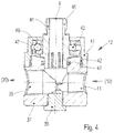
- FIG. 4 shows an enlarged cross section of the rotary joint
- FIG. 5 shows a cross section according to the line V-V through the support arm of the ceiling boom.
- FIGS. 1 and 2 illustrate a ceiling boom 1 which in the preferred embodiment is equipped with an interior heating cable 10 that is led inside the high-pressure hose 30 .
- a bearing shaft 14 is nonrotatably connected to the ceiling plate 6 .
- the bearing shaft 14 leads through the ceiling plate 6 , and at that location has a connecting sleeve 7 for introducing an electric cable, and also has a connecting sleeve 8 for introducing the high-pressure medium.
- the high-pressure medium according to FIG. 1 is introduced at the side via a suitable high-pressure water connection 13 , and flows around the heating cartridge.
- the bearing shaft 14 is fixedly connected to the ceiling plate 6 , and leads through a pivot bearing 5 which as a whole is made up of different bearing parts, namely, a rotational power distributor 25 and a rotary joint 12 situated beneath it.
- the pivot bearing 5 has an exterior jacket tube 35 that is connected to the rotatable portion of the ceiling boom 1 , and two mutually parallel side plates 4 , which accommodate a support arm 2 between them that is preferably made of a metal material, engage with the jacket tube 35 .
- the support arm 2 is designed as a circular metal tube, to which the invention is not limited.
- Other profile shapes of a support arm 2 may also be used, such as a support strut or a strut assembly, so that it is not necessary to lead the high-pressure hose 30 inside the support arm 2 .
- the high-pressure hose may thus also be led on the outer circumference of a support arm.
- the support arm 2 is made of a circular metal tube 3 , which on its front opening side is connected to a guide tube 17 through which the high-pressure hose 30 is led.
- One end of a relieving spring 18 is fastened to the output side of the guide tube 17 , and the other end of the relieving spring is fixedly connected to a rotary joint 19 through which the high-pressure hose 30 is led.
- a suitable washing device such as a washing brush, a high-pressure gun, or a washing lance may be connected to the connecting nipple 20 , also using an intermediate hose for this connection.
- the washing device is not directly connected to the connecting nipple 20 , and instead a connecting hose is connected at that location, into which the heating cable 10 extends over any desired length.
- the heating cable 10 may end in the area of the rotary joint 19 or in front of the rotary joint.
- the heating cable 10 may also be longer than the connecting hose (not shown), and may be inserted into the washing device in order to heat it as well.
- a connecting nipple 9 is situated on the pivot bearing 5 on the ceiling side, and that the multicore power cable is led out through the connecting nipple in order to be electroconductively connected to the cable cores 52 of the heating cable 10 .
- FIG. 1 further illustrates that the high-pressure hose 30 is also enclosed by an insulation hose 16 , at least over the length of the ceiling boom, in order to achieve additional thermal insulation.
- an upper protective cap 22 is provided to prevent penetration of water from above into the pivot bearing 5 .
- the rotational axis of the ceiling boom 1 is denoted overall by reference numeral 15 .
- FIG. 3 Further particulars of the pivot bearing 5 in conjunction with the rotary joint 12 situated therebeneath are apparent in FIG. 3 .
- the duct 53 is provided for insertion of a heating cartridge, with the high-pressure water connection 13 opening perpendicularly into the duct, so that the high-pressure medium may be heated when a heating cartridge is inserted into the duct 53 .
- the connecting sleeve 8 for the introduction of the high-pressure water may therefore perform multiple functions.
- the pivot joint 5 is made up essentially of an exterior jacket tube 35 that is nonrotatably connected to the support arm 2 and the side plates 4 .
- two spaced-apart radial bearings 23 , 24 are provided, whose inner bearing ring is nonrotatably connected to the stationary bearing shaft 14 , while the outer ring is fixedly connected to the jacket tube 35 .
- the rotational power distributor 25 which is made up essentially of an inner ring 26 that is nonrotatably connected to the bearing shaft 14 via an associated locking ball 29 , while the outer ring 27 is nonrotatably connected to the rotating jacket tube 35 via an adjustable grub screw 28 .
- the power feed via a multicore cable is provided via the upper connecting sleeve 7 and into a longitudinal hole 32 that is guided approximately in parallel to the water duct 31 .
- the longitudinal hole 32 guides a number of cables, the radial portion of a cable harness 33 in the insertion area at the inner ring 26 being illustrated.
- the inner ring 26 is electroconductively connected to the outer ring 27 via a flat annular slip ring 34 , wherein a multicore power feed into a cable harness 36 situated on the outer ring 27 on the output side takes place via the slip ring 34 and electrical contacts that make contact at that location.
- the slip rings may, for example, be made up of electrically conductive circular ring-shaped sector areas that are electrically insulated from one another, wherein, for example, spring-loaded contact pins that are connected to the electrical feed lines are mounted on each sector area.
- the introduction of the heating cable 10 in a pressure-tight manner may also take place via a high-pressure cable connection 11 , resistant to high pressure, into the lower rotary joint 12 , where, according to the schematic illustration in FIG. 3 , the heating cable 30 is now led through the rotary joint 12 and inserted coaxially into the interior of the high-pressure hose 30 .
- the high-pressure hose is connected to a suitable connecting nipple at the outflow opening 39 of the rotary joint 12 , and the high-pressure cable connection 11 is likewise designed in such a way that high-pressure medium cannot penetrate from the outside.
- the rotary joint 12 according to FIG. 3 is described in greater detail in FIG. 4 .
- the rotary joint is made up essentially of a rotating housing 37 , on the right side of which the connection for the high-pressure cable connection 11 is provided, and on the left side of which the outflow opening 39 for the connection of the high-pressure hose 30 is provided.
- the housing 37 has an approximately sleeve-shaped design, and via an O-ring 40 rests with sealing against the outer circumference of the fixed screw sleeve 45 .
- the screw sleeve 45 has a screw terminal 44 , to which the rotary joint 12 together with the bearing shaft 14 is connected according to FIG. 3 .
- the rotary joint 12 is made up of an axial bearing 43 that forms two separate bearing rings 46 , 47 .
- Known rolling elements such as balls, rollers, or the like are situated between the bearing rings 46 , 47 .
- the top bearing ring 46 is nonrotatably connected to the housing 37 of the rotary joint 12 via a screw connection 42 , while the other bearing ring 47 is nonrotatably connected to the screw sleeve 45 , which in turn is nonrotatably connected to the bearing shaft 14 .
- a sealing plug 38 is situated on the bottom side of the housing 37 to allow the screw sleeve 45 to be screwed onto the bearing shaft 14 .
- FIG. 5 illustrates a cross section of the support arm 2 , which in the exemplary embodiment shown is designed as a circular tube 3 .
- an insulation hose 16 which in its interior 49 accommodates the high-pressure hose 30 , which in turn in its interior 50 accommodates the heating cable 10 provided with multiple cable cores 52 .
- the heating cable 10 is thus freely guided inside the high-pressure hose 30 , and the high-pressure medium flows around it.
- the heating cable does not result in flow obstruction, since its cross section is significantly smaller than the inner cross section of the high-pressure hose.
- the heating cable 10 preferably has an insulating jacket 51 .
- the insulation hose 16 encloses the outer circumference of the high-pressure hose 30 in a form-fit manner without formation of a space-containing interior 49 .
- a number of signal cables 54 may also be guided at the outer circumference of the high-pressure hose, wherein these signal cables are either likewise current-conducting to conduct a heating current, or conduct a signal current.
Landscapes
- Engineering & Computer Science (AREA)
- Mechanical Engineering (AREA)
- Pipe Accessories (AREA)
- Electric Cable Arrangement Between Relatively Moving Parts (AREA)
- Joints Allowing Movement (AREA)
Abstract
Description
- 1. In a first embodiment, on the output side of the rotational power distributor a multicore cable design is provided that is in direct electroconductive connection with the at least two-core heating cable. In this case, the heating cable is introduced into a rotary joint via a high-pressure cable connection with suitable high pressure resistance, and the connection for the high-pressure hose is also situated on the other side of the rotary joint, so that by leading the heating cable through and inserting it into the rotary joint, it is now possible for the first time to guide the heating cable inside the high-pressure hose with sealing.
- 2. Instead of introducing the heating cable into the interior of the high-pressure hose, in another embodiment it is provided that multiple cables are once again led out at the output of the rotational power distributor, but are then supplied to a heating jacket that encloses the high-pressure hose on the outer circumference.
- 3. In a third embodiment, it is provided that instead of the multicore power cables for supplying power to the interior or exterior heating cable or the heating jacket, it is provided that additional signal cables are used which are introduced at the outer circumference of the high-pressure hose and enclose same, so that it is possible for the first time to also carry signal cables, situated on the outer circumference of the high-pressure hose, preferably embedded in its jacket, along with the rotating high-pressure hose.
- Of course, it is possible to design the hose jacket of the high-pressure hose in such a way that conductive paths may be directly provided at that location to allow a signal transmission from the output of the rotational power distributor, via the high-pressure hose, in the direction of the washing device.
- 4. In one refinement of the invention, it is provided that in addition to the use of a heating cable, which is preferably internally situated in the high-pressure hose, but also externally on the high-pressure hose, a multicore signal transmission also takes place. Thus, within the scope of the present invention a combination of heating and signal transmission is provided.
- Such signal cables may be provided, for example, for illuminating LED elements, and that are situated along the support arm or that enclose the high-pressure hose, or that supply power or signals to the washing device that is connected to the high-pressure hose.
- In the preferred embodiment, in which the heating cable is inserted into the interior of the high-pressure hose in a pressure-tight manner, it is presumed that the high-pressure hose is introduced via a suitable high-pressure cable connection rotary joint with resistance to high pressure, and at the same time, the input side of the high-pressure hose is connected at the output side of the rotary joint with resistance to high pressure.
- 1 ceiling boom
- 2 support arm
- 3 circular tube
- 4 side plate
- 5 pivot bearing
- 6 ceiling plate
- 7 connecting sleeve (electrical)
- 8 connecting sleeve (water)
- 9 connecting sleeve (electrical)
- 10 heating cable
- 11 high-pressure cable connection
- 12 rotary joint
- 13 high-pressure water connection
- 14 bearing shaft
- 15 rotational axis
- 16 insulation hose
- 17 guide tube
- 18 relieving spring
- 19 rotary joint
- 20 connecting nipple
- 21 fastening hole
- 22 protective cap
- 23 radial bearing (top)
- 24 radial bearing (bottom)
- 25 rotational power distributor
- 26 inner ring
- 27 outer ring
- 28 grub screw
- 29 locking ball
- 30 high-pressure hose
- 31 water duct
- 32 longitudinal hole (electrical)
- 33 cable harness (incoming)
- 34 slip ring
- 35 jacket tube
- 36 cable harness (outgoing)
- 37 housing (of 12)
- 38 sealing plug (of 12)
- 39 outflow opening
- 40 O-ring
- 41 outer housing (of 12)
- 42 screw connection
- 43 axial bearing (of 12)
- 44 screw terminal (of 12)
- 45 screw sleeve
- 46 bearing ring (top)
- 47 bearing ring (bottom)
- 48 cavity
- 49 interior (of 16)
- 50 interior (high-pressure hose 30)
- 51 insulating jacket (of 10)
- 52 cable core
- 53 duct (for heating cartridge)
- 54 signal cable
Claims (17)
Applications Claiming Priority (2)
| Application Number | Priority Date | Filing Date | Title |
|---|---|---|---|
| DE102018121959.8 | 2018-09-10 | ||
| DE102018121959.8A DE102018121959A1 (en) | 2018-09-10 | 2018-09-10 | Heated top gyro for high-pressure washing of vehicles |
Publications (2)
| Publication Number | Publication Date |
|---|---|
| US20200079329A1 US20200079329A1 (en) | 2020-03-12 |
| US11518347B2 true US11518347B2 (en) | 2022-12-06 |
Family
ID=67587605
Family Applications (1)
| Application Number | Title | Priority Date | Filing Date |
|---|---|---|---|
| US16/564,319 Active 2041-03-09 US11518347B2 (en) | 2018-09-10 | 2019-09-09 | Heatable ceiling boom for the high-pressure washing of vehicles |
Country Status (4)
| Country | Link |
|---|---|
| US (1) | US11518347B2 (en) |
| EP (1) | EP3620333B1 (en) |
| CA (1) | CA3054211C (en) |
| DE (1) | DE102018121959A1 (en) |
Citations (8)
| Publication number | Priority date | Publication date | Assignee | Title |
|---|---|---|---|---|
| DE9107952U1 (en) | 1991-06-28 | 1992-01-09 | Mosmatic Ag, Necker | Ceiling carousel for washing facilities |
| DE9414483U1 (en) | 1994-09-07 | 1995-02-23 | Mosmatic Ag, Necker | Ceiling gyroscope for high-pressure washing devices |
| JPH08247346A (en) | 1995-03-09 | 1996-09-27 | Nichifu Co Ltd | Water conveying hose for automatic car washer |
| DE19642847C2 (en) | 1996-10-17 | 1999-08-19 | Mosmatic Ag | Ceiling gyroscope for self-service car washes |
| US20010015385A1 (en) * | 1998-09-04 | 2001-08-23 | Mannesmann Vdo Ag | Heatable washer system which is intended for a motor vehicle |
| DE10060316A1 (en) | 2000-12-04 | 2002-06-13 | Paul Rosenberger | Heatable hose for e.g. water and aqueous mixtures in car wash installations, comprises first hose part with heating wire and second hose part without wire |
| DE10241829A1 (en) | 2002-09-09 | 2004-03-18 | Mosmatic Ag | Ceiling mounted revolver of car wash has magnetic position holder installed between rotatable revolving arm and optional stationary element of washing bay and which releasably keeps arm in initial position |
| DE102007022260A1 (en) | 2007-05-09 | 2008-11-27 | Mosmatic Ag | Washing device for car wash has high pressure generators via which media can be fed to wash bay in separate lines, medium switch(es) in wash bay near overhead device(s) controlled by selection switch, outlet to wash brush(es)/spray gun(s) |
Family Cites Families (1)
| Publication number | Priority date | Publication date | Assignee | Title |
|---|---|---|---|---|
| DE4307371A1 (en) * | 1993-03-09 | 1994-09-15 | Hit Hillesheim Innovations Und | Heatable line for a flow medium |
-
2018
- 2018-09-10 DE DE102018121959.8A patent/DE102018121959A1/en not_active Withdrawn
-
2019
- 2019-08-09 EP EP19190955.5A patent/EP3620333B1/en active Active
- 2019-09-05 CA CA3054211A patent/CA3054211C/en active Active
- 2019-09-09 US US16/564,319 patent/US11518347B2/en active Active
Patent Citations (8)
| Publication number | Priority date | Publication date | Assignee | Title |
|---|---|---|---|---|
| DE9107952U1 (en) | 1991-06-28 | 1992-01-09 | Mosmatic Ag, Necker | Ceiling carousel for washing facilities |
| DE9414483U1 (en) | 1994-09-07 | 1995-02-23 | Mosmatic Ag, Necker | Ceiling gyroscope for high-pressure washing devices |
| JPH08247346A (en) | 1995-03-09 | 1996-09-27 | Nichifu Co Ltd | Water conveying hose for automatic car washer |
| DE19642847C2 (en) | 1996-10-17 | 1999-08-19 | Mosmatic Ag | Ceiling gyroscope for self-service car washes |
| US20010015385A1 (en) * | 1998-09-04 | 2001-08-23 | Mannesmann Vdo Ag | Heatable washer system which is intended for a motor vehicle |
| DE10060316A1 (en) | 2000-12-04 | 2002-06-13 | Paul Rosenberger | Heatable hose for e.g. water and aqueous mixtures in car wash installations, comprises first hose part with heating wire and second hose part without wire |
| DE10241829A1 (en) | 2002-09-09 | 2004-03-18 | Mosmatic Ag | Ceiling mounted revolver of car wash has magnetic position holder installed between rotatable revolving arm and optional stationary element of washing bay and which releasably keeps arm in initial position |
| DE102007022260A1 (en) | 2007-05-09 | 2008-11-27 | Mosmatic Ag | Washing device for car wash has high pressure generators via which media can be fed to wash bay in separate lines, medium switch(es) in wash bay near overhead device(s) controlled by selection switch, outlet to wash brush(es)/spray gun(s) |
Non-Patent Citations (4)
| Title |
|---|
| DE10060316B4 (Year: 2008). * |
| DE102007022260A1—machine translation (Year: 2007). * |
| DE19642847A1 (Year: 1998). * |
| DE4307371A1—machine translation (Year: 1994). * |
Also Published As
| Publication number | Publication date |
|---|---|
| US20200079329A1 (en) | 2020-03-12 |
| EP3620333B1 (en) | 2021-05-05 |
| CA3054211A1 (en) | 2020-03-10 |
| CA3054211C (en) | 2021-10-19 |
| DE102018121959A1 (en) | 2020-03-12 |
| EP3620333A1 (en) | 2020-03-11 |
Similar Documents
| Publication | Publication Date | Title |
|---|---|---|
| US12431648B2 (en) | Connection element for electrically connecting a fluid-coolable individual line, fluid-coolable individual line unit, and charging cable | |
| US10029575B2 (en) | Electric line arrangement | |
| US6402524B2 (en) | Data transfer system | |
| US7772506B2 (en) | Fluid-tight cable duct | |
| KR100303959B1 (en) | Plasma gun head | |
| WO2019184882A1 (en) | Parallel cold liquid-cooled cable for exclusive use of high-power charging pile positive pole and negative pole | |
| US11518347B2 (en) | Heatable ceiling boom for the high-pressure washing of vehicles | |
| US3847287A (en) | Single-pole electrical plug connection for shielded arc welding apparatus | |
| GB1481806A (en) | Welding gun assembly | |
| JP3405989B2 (en) | Swivel connection device | |
| US10750575B2 (en) | Heated floor panel system for an aircraft | |
| US20070237497A1 (en) | Means for influencing the temperature of flowable media, especially of lubricants found in a lubricant system | |
| US4509178A (en) | Arrangement of an electrode for electric arc furnaces | |
| RU2008103963A (en) | ELECTRICAL THERMOSTATING SYSTEM FOR PIPELINES OR TANKS | |
| US4443683A (en) | Angular and swiveling head for gas consuming electric welding torches | |
| US2359351A (en) | Connecting device | |
| CN203055499U (en) | A water-cooled cable | |
| CN203912221U (en) | Carbon fiber electrical-warming type three-pin joint | |
| SE9503707D0 (en) | Heat insulated pipeline | |
| CN206697660U (en) | A kind of common cable connector | |
| CN105784153A (en) | Overtemperature indication spacer | |
| US1560673A (en) | Electric heater for automobile radiators | |
| CN120511111B (en) | Waterproof crosslinked polyethylene insulated power cable resistant to electromagnetic interference | |
| CN113389951A (en) | Multifunctional pipe | |
| CN222052592U (en) | Wire and cable with fireproof sleeve |
Legal Events
| Date | Code | Title | Description |
|---|---|---|---|
| FEPP | Fee payment procedure |
Free format text: ENTITY STATUS SET TO UNDISCOUNTED (ORIGINAL EVENT CODE: BIG.); ENTITY STATUS OF PATENT OWNER: SMALL ENTITY |
|
| FEPP | Fee payment procedure |
Free format text: ENTITY STATUS SET TO SMALL (ORIGINAL EVENT CODE: SMAL); ENTITY STATUS OF PATENT OWNER: SMALL ENTITY |
|
| STPP | Information on status: patent application and granting procedure in general |
Free format text: DOCKETED NEW CASE - READY FOR EXAMINATION |
|
| AS | Assignment |
Owner name: MOSMATIC AG, SWITZERLAND Free format text: ASSIGNMENT OF ASSIGNORS INTEREST;ASSIGNORS:RIEBEN, PATRICK;SANTORO, DANIEL;REEL/FRAME:056909/0857 Effective date: 20190920 |
|
| STPP | Information on status: patent application and granting procedure in general |
Free format text: NON FINAL ACTION MAILED |
|
| STPP | Information on status: patent application and granting procedure in general |
Free format text: RESPONSE TO NON-FINAL OFFICE ACTION ENTERED AND FORWARDED TO EXAMINER |
|
| STPP | Information on status: patent application and granting procedure in general |
Free format text: FINAL REJECTION MAILED |
|
| STPP | Information on status: patent application and granting procedure in general |
Free format text: RESPONSE AFTER FINAL ACTION FORWARDED TO EXAMINER |
|
| STPP | Information on status: patent application and granting procedure in general |
Free format text: NOTICE OF ALLOWANCE MAILED -- APPLICATION RECEIVED IN OFFICE OF PUBLICATIONS |
|
| STPP | Information on status: patent application and granting procedure in general |
Free format text: PUBLICATIONS -- ISSUE FEE PAYMENT RECEIVED |
|
| STPP | Information on status: patent application and granting procedure in general |
Free format text: PUBLICATIONS -- ISSUE FEE PAYMENT VERIFIED |
|
| STCF | Information on status: patent grant |
Free format text: PATENTED CASE |