US11518108B2 - Manufacturing apparatus - Google Patents
Manufacturing apparatus Download PDFInfo
- Publication number
- US11518108B2 US11518108B2 US16/984,298 US202016984298A US11518108B2 US 11518108 B2 US11518108 B2 US 11518108B2 US 202016984298 A US202016984298 A US 202016984298A US 11518108 B2 US11518108 B2 US 11518108B2
- Authority
- US
- United States
- Prior art keywords
- accumulation amount
- manufacturing
- manufacturing material
- twisting force
- manufacturing apparatus
- Prior art date
- Legal status (The legal status is an assumption and is not a legal conclusion. Google has not performed a legal analysis and makes no representation as to the accuracy of the status listed.)
- Active, expires
Links
Images


Classifications
-
- B—PERFORMING OPERATIONS; TRANSPORTING
- B29—WORKING OF PLASTICS; WORKING OF SUBSTANCES IN A PLASTIC STATE IN GENERAL
- B29C—SHAPING OR JOINING OF PLASTICS; SHAPING OF MATERIAL IN A PLASTIC STATE, NOT OTHERWISE PROVIDED FOR; AFTER-TREATMENT OF THE SHAPED PRODUCTS, e.g. REPAIRING
- B29C64/00—Additive manufacturing, i.e. manufacturing of three-dimensional [3D] objects by additive deposition, additive agglomeration or additive layering, e.g. by 3D printing, stereolithography or selective laser sintering
- B29C64/30—Auxiliary operations or equipment
- B29C64/386—Data acquisition or data processing for additive manufacturing
- B29C64/393—Data acquisition or data processing for additive manufacturing for controlling or regulating additive manufacturing processes
-
- B—PERFORMING OPERATIONS; TRANSPORTING
- B29—WORKING OF PLASTICS; WORKING OF SUBSTANCES IN A PLASTIC STATE IN GENERAL
- B29C—SHAPING OR JOINING OF PLASTICS; SHAPING OF MATERIAL IN A PLASTIC STATE, NOT OTHERWISE PROVIDED FOR; AFTER-TREATMENT OF THE SHAPED PRODUCTS, e.g. REPAIRING
- B29C53/00—Shaping by bending, folding, twisting, straightening or flattening; Apparatus therefor
- B29C53/16—Straightening or flattening
-
- B—PERFORMING OPERATIONS; TRANSPORTING
- B29—WORKING OF PLASTICS; WORKING OF SUBSTANCES IN A PLASTIC STATE IN GENERAL
- B29C—SHAPING OR JOINING OF PLASTICS; SHAPING OF MATERIAL IN A PLASTIC STATE, NOT OTHERWISE PROVIDED FOR; AFTER-TREATMENT OF THE SHAPED PRODUCTS, e.g. REPAIRING
- B29C64/00—Additive manufacturing, i.e. manufacturing of three-dimensional [3D] objects by additive deposition, additive agglomeration or additive layering, e.g. by 3D printing, stereolithography or selective laser sintering
- B29C64/10—Processes of additive manufacturing
- B29C64/106—Processes of additive manufacturing using only liquids or viscous materials, e.g. depositing a continuous bead of viscous material
- B29C64/118—Processes of additive manufacturing using only liquids or viscous materials, e.g. depositing a continuous bead of viscous material using filamentary material being melted, e.g. fused deposition modelling [FDM]
-
- B—PERFORMING OPERATIONS; TRANSPORTING
- B29—WORKING OF PLASTICS; WORKING OF SUBSTANCES IN A PLASTIC STATE IN GENERAL
- B29C—SHAPING OR JOINING OF PLASTICS; SHAPING OF MATERIAL IN A PLASTIC STATE, NOT OTHERWISE PROVIDED FOR; AFTER-TREATMENT OF THE SHAPED PRODUCTS, e.g. REPAIRING
- B29C64/00—Additive manufacturing, i.e. manufacturing of three-dimensional [3D] objects by additive deposition, additive agglomeration or additive layering, e.g. by 3D printing, stereolithography or selective laser sintering
- B29C64/30—Auxiliary operations or equipment
- B29C64/307—Handling of material to be used in additive manufacturing
- B29C64/321—Feeding
-
- B—PERFORMING OPERATIONS; TRANSPORTING
- B33—ADDITIVE MANUFACTURING TECHNOLOGY
- B33Y—ADDITIVE MANUFACTURING, i.e. MANUFACTURING OF THREE-DIMENSIONAL [3D] OBJECTS BY ADDITIVE DEPOSITION, ADDITIVE AGGLOMERATION OR ADDITIVE LAYERING, e.g. BY 3D PRINTING, STEREOLITHOGRAPHY OR SELECTIVE LASER SINTERING
- B33Y10/00—Processes of additive manufacturing
-
- B—PERFORMING OPERATIONS; TRANSPORTING
- B33—ADDITIVE MANUFACTURING TECHNOLOGY
- B33Y—ADDITIVE MANUFACTURING, i.e. MANUFACTURING OF THREE-DIMENSIONAL [3D] OBJECTS BY ADDITIVE DEPOSITION, ADDITIVE AGGLOMERATION OR ADDITIVE LAYERING, e.g. BY 3D PRINTING, STEREOLITHOGRAPHY OR SELECTIVE LASER SINTERING
- B33Y40/00—Auxiliary operations or equipment, e.g. for material handling
-
- B—PERFORMING OPERATIONS; TRANSPORTING
- B33—ADDITIVE MANUFACTURING TECHNOLOGY
- B33Y—ADDITIVE MANUFACTURING, i.e. MANUFACTURING OF THREE-DIMENSIONAL [3D] OBJECTS BY ADDITIVE DEPOSITION, ADDITIVE AGGLOMERATION OR ADDITIVE LAYERING, e.g. BY 3D PRINTING, STEREOLITHOGRAPHY OR SELECTIVE LASER SINTERING
- B33Y50/00—Data acquisition or data processing for additive manufacturing
- B33Y50/02—Data acquisition or data processing for additive manufacturing for controlling or regulating additive manufacturing processes
-
- B—PERFORMING OPERATIONS; TRANSPORTING
- B33—ADDITIVE MANUFACTURING TECHNOLOGY
- B33Y—ADDITIVE MANUFACTURING, i.e. MANUFACTURING OF THREE-DIMENSIONAL [3D] OBJECTS BY ADDITIVE DEPOSITION, ADDITIVE AGGLOMERATION OR ADDITIVE LAYERING, e.g. BY 3D PRINTING, STEREOLITHOGRAPHY OR SELECTIVE LASER SINTERING
- B33Y30/00—Apparatus for additive manufacturing; Details thereof or accessories therefor
Definitions
- the present disclosure relates to a manufacturing apparatus for applying a manufacturing material.
- stack additive manufacturing apparatuses for stacking filaments to form an object (for example, U.S. Pat. No. 10,046,511).
- Non-limiting embodiments of the present disclosure relate to a manufacturing apparatus capable of reducing a twisting force accumulated in a manufacturing material as compared with a case of continuing manufacturing regardless of a twisted state of the manufacturing material.
- aspects of certain non-limiting embodiments of the present disclosure address the above advantages and/or other advantages not described above. However, aspects of the non-limiting embodiments are not required to address the advantages described above, and aspects of the non-limiting embodiments of the present disclosure may not address advantages described above.
- a manufacturing apparatus including an acquisition unit and an elimination unit.
- the acquisition unit is configured to acquire information relating to an accumulation amount of a twisting force generated in a linear manufacturing material during applying.
- the elimination unit is configured to eliminate the twisting force based on the information relating to the accumulation amount.
- FIG. 1 is a schematic diagram illustrating a manufacturing apparatus according to a first exemplary embodiment
- FIG. 2 is a perspective view illustrating an example of an object to be manufactured
- FIG. 3 is a diagram illustrating a procedure for manufacturing the object
- FIG. 4 is a diagram illustrating that an application direction of a manufacturing material is changed
- FIG. 5 is a flowchart of a process for acquiring an accumulation amount
- FIG. 6 is a flowchart of an elimination process
- FIG. 7 is a flowchart of a twist elimination process ( 1 );
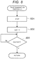
- FIG. 8 is a flowchart of a twist elimination process ( 2 );
- FIG. 9 is a schematic diagram illustrating a manufacturing apparatus according to a second exemplary embodiment.
- FIG. 10 is a flowchart of a twist elimination process ( 3 );
- FIG. 11 is a flowchart of a process for changing an application direction according to a third exemplary embodiment
- FIG. 12 is a schematic diagram illustrating a manufacturing apparatus according to a fourth exemplary embodiment
- FIG. 13 is a schematic diagram illustrating a detector according to the fourth exemplary embodiment.
- FIG. 14 is a schematic diagram illustrating a manufacturing apparatus according to a fifth exemplary embodiment
- FIG. 15 is a schematic diagram illustrating a detector according to the fifth exemplary embodiment.
- FIG. 16 is a schematic diagram illustrating a part of a manufacturing apparatus according to a sixth exemplary embodiment.
- FIG. 17 is a schematic diagram illustrating a part of a manufacturing apparatus according to a seventh exemplary embodiment.
- FIG. 1 is a diagram illustrating a manufacturing apparatus 10 according the present exemplary embodiment.
- the manufacturing apparatus 10 is an apparatus for manufacturing a three-dimensional object based on shape data.
- the manufacturing apparatus 10 includes a table 14 having a manufacturing surface 12 on which an object is manufactured, and a supply device 18 that supplies a manufacturing material 16 to the table 14 .
- the table 14 is supported by, for example, a drive table 20 .
- the drive table 20 operates according to a drive signal from a control device 22 .
- the control device 22 outputs the drive signal to the drive table 20 based on the shape data of the object.
- the drive table 20 drives the table 14 in an X-Y direction along a horizontal plane, a height direction (up direction UH and down direction DH), and a rotation direction according to the drive signal. Accordingly, the object is manufactured on the manufacturing surface 12 with the manufacturing material 16 delivered from the supply device 18 to the table 14 .
- the present disclosure is not limited to this case.
- the supply device 18 may be driven by a manipulator based on the shape data to manufacture the object.
- the supply device 18 includes a support shaft 30 .
- a reel 32 is rotatably supported on the support shaft 30 .
- the supply device 18 includes a change roller 34 , a transport unit 36 , and a cutting machine 38 .
- the change roller 34 changes a delivery direction of the manufacturing material 16 delivered from the reel 32 .
- the manufacturing material 16 whose delivery direction is changed by the change roller 34 is delivered to the transport unit 36 .
- the cutting machine 38 cuts the manufacturing material 16 delivered from the transport unit 36 .
- the supply device 18 further includes a manufacturing nozzle 40 and a pressure roller 42 .
- the manufacturing nozzle 40 melts the manufacturing material 16 delivered from the cutting machine 38 .
- the pressure roller 42 presses the manufacturing material 16 delivered from the manufacturing nozzle 40 to a target location.
- the reel 32 holds the linear manufacturing material 16 in a wound state.
- the reel 32 holds the wound manufacturing material 16 in a drawable manner.
- the manufacturing material 16 contains plural continuous fibers and a resin impregnated into the continuous fibers.
- An example of the continuous fiber is a carbon fiber.
- the resin impregnated into the continuous fibers contains a thermoplastic resin. Accordingly, the manufacturing material 16 can be softened and deformed when being heated, and is cured at a room temperature to maintain its shape.
- the transport unit 36 is connected to the control device 22 and operates according to a transport signal from the control device 22 .
- the transport unit 36 includes, for example, drive rollers that sandwich the manufacturing material 16 from both sides. When the drive rollers operate according to the transport signal, the transport unit 36 pulls out the manufacturing material 16 wound on the reel 32 and sends the manufacturing material 16 to the cutting machine 38 .
- the cutting machine 38 is an example of an elimination unit as hardware.
- the cutting machine 38 is connected to the control device 22 and operates according to a cutting signal from the control device 22 .
- the cutting machine 38 includes upstream rollers 46 , downstream rollers 50 , and a cutter 52 .
- the upstream rollers 46 are disposed upstream 44 in a manufacturing material transport direction.
- the downstream rollers 50 are disposed downstream 48 in the manufacturing material transport direction.
- the cutter 52 is disposed between the upstream rollers 46 and the downstream rollers 50 .
- the cutter 52 includes, for example, a shearing mechanism that shears the manufacturing material 16 passing therethrough. The cutter 52 shears the manufacturing material 16 when receiving the cutting signal from the control device 22 .
- the manufacturing nozzle 40 heats the manufacturing material 16 delivered from the cutting machine 38 to melt the resin of the manufacturing material 16 .
- the manufacturing nozzle 40 delivers the molten manufacturing material 16 toward the target location.
- target location covers a concept including the manufacturing surface 12 of the table 14 and a part on the manufacturing material 16 applied on the table 14 .
- part on the table 14 covers a concept including a part on the manufacturing surface 12 of the table 14 and the part on the manufacturing material 16 applied on the table 14 .
- the pressure roller 42 presses the manufacturing material 16 delivered from the manufacturing nozzle 40 to the target location, and fixes the manufacturing material 16 at the target location.
- target location and the term “part on the table 14 ” cover the above-described concepts.
- FIG. 2 is a diagram illustrating an example of an object 54 to be manufactured by the manufacturing apparatus 10 .
- FIG. 3 is a diagram illustrating an application path 56 along which the manufacturing material 16 is applied when the object 54 is manufactured.
- the application path 56 indicates an application route calculated by the control device 22 based on the shape data of the object 54 when the object 54 is three-dimensionally manufactured.
- the manufacturing apparatus 10 manufactures the object 54 by applying the manufacturing material 16 along the application path 56 .
- FIG. 4 is a diagram illustrating a location 58 where the application direction of the manufacturing material 16 is changed and illustrates that the application direction of the manufacturing material 16 is changed 180 degrees to the right when viewed from the manufacturing apparatus 10 .
- the control device 22 is configured with a microcomputer including a CPU serving as a processor, a ROM that stores a program showing a procedure in accordance with which the CPU processes, and a RAM.
- the control device 22 operates according to an operation of the microcomputer.
- the ROM stores information on the manufacturing apparatus 10 , information on the manufacturing material 16 to be used, and a twist limit of the manufacturing material 16 .
- a distance from a reel outlet 60 , indicating a position of the manufacturing material 16 delivered from the reel 32 , to the downstream rollers 50 disposed on the manufacturing nozzle 40 side is 1,000 mm.
- the ROM stores this distance as the information on the manufacturing apparatus 10 .
- the ROM stores the information on the manufacturing material 16 to be used.
- the information on the manufacturing material 16 to be used includes a shape, a material, and physical property values of the manufacturing material 16 to be used.
- the manufacturing material 16 has a diameter of 0.6 mm and a Vf value, indicating a volume ratio of the continuous fibers contained in the manufacturing material 16 , of 45%.
- the continuous fibers constituting the manufacturing material 16 contain 3,000 carbon fibers.
- the resin constituting the manufacturing material 16 contains 57% of polypropylene (PP), 39% of polyamide (PA), and 4% of maleic PP.
- the ROM stores these pieces of information on the manufacturing material 16 .
- the inventors finds that in a case of manufacturing the object 54 by the manufacturing apparatus 10 having the above configuration with the manufacturing material 16 described above, if an accumulation amount of a twisting force generated in the manufacturing material 16 is larger than a specified value (allowable value), the transport of the manufacturing material 16 may be hindered and a manufacturing process may be hindered.
- a specified value allowable value
- a specific example of hindering the manufacturing process is that the applied manufacturing material 16 is distorted or broken, which may result in that the strength of the manufacturing material 16 is reduced.
- accumulated rotation angles in the right and left directions are regarded as right and left direction change amounts, respectively, and the respective accumulated numbers of rotations are regarded as the numbers of changes in the right and left directions.
- a twist limit of the right and left direction change amounts indicating the accumulated rotation angles is set to 3,600 degrees, and a twist limit of the numbers of changes in the right and left directions indicating the accumulated numbers of rotations is set to 10 rotations.
- the above twist limits are stored in the ROM.
- 3600 degrees which indicates the right and left direction change amounts indicating the accumulated rotation angles, indicates a threshold value.
- This threshold value may be referred to as a specified value (allowable value).
- 10 rotations which indicate the numbers of changes in the right and left directions indicating the accumulated numbers of rotations, indicates a threshold value.
- This threshold value may be referred to as a specified value (allowable value).
- a value smaller than the threshold value is set as a determination reference value.
- the determination reference value is set to 3,420 degrees (9.5 rotations), which is 180 degrees (half rotation) smaller than 3,600 degrees (10 rotations) which is the right and left direction change amounts.
- the determination reference value is stored in the ROM.
- Each of the right and left direction change amounts indicating the accumulated rotation angles in the right and left directions is obtained by adding a rotation angle in the same direction and subtracting a rotation angle in an opposite direction. Further, each of the numbers of changes in the right and left directions indicating the accumulated numbers of rotations is obtained by adding a rotation number in the same direction and subtracting a rotation number in the opposite direction.
- the twist limit of the manufacturing material 16 is determined based on the information on the manufacturing apparatus 10 and the information on the manufacturing material 16 described above. It is noted that the present disclosure is not limited thereto. For example, the twist limit may be determined based on the following parameters.
- Manufacturing Material a resin composition, a diameter, the number of continuous fibers, a material of continuous fiber, a Vf value, and a moisture absorption rate
- Manufacturing Condition a manufacturing speed (a consumed length of a manufacturing material per hour) and a melting temperature
- FIGS. 5 to 7 are flowcharts illustrating operations of the present exemplary embodiment. The operations of the manufacturing apparatus 10 will be described according to the flowcharts.
- the CPU of the microcomputer constituting the control device 22 starts an operation according to the program stored in the ROM.
- a process for acquiring an accumulation amount is called from the manufacturing process for performing the manufacturing, the process for acquiring an accumulation amount is executed as illustrated in FIG. 5 .
- the process for acquiring an accumulation amount implements an acquisition unit that acquires information relating to the accumulation amount of the twisting force generated in the manufacturing material 16 during applying, so as to acquire the information relating to the accumulation amount based on the application path 56 along which the manufacturing material 16 is applied.
- the process for acquiring an accumulation amount it is determined whether the application direction of the manufacturing material 16 is changed to the left during the manufacturing, based on data of the application path 56 along which the manufacturing material 16 is applied (S 1 ).
- a rotation angle to the left direction is added to a left accumulation amount (left direction change amount) stored in the RAM (S 2 ).
- the rotation angle to the left direction is subtracted from a right accumulation amount (right direction change amount) stored in the RAM (S 3 ), and the flow returns to a routine that has called the process for acquiring an accumulation amount.
- the left accumulation amount indicating the information relating to the accumulation amount is the left direction change amount on the application path 56 along which the manufacturing material 16 is applied. It is noted that the left accumulation amount is 0 in an initial state. Each accumulation amount may have a negative value.
- the left accumulation amount indicating the direction change amount may be the number of changes in the left direction. In this case, the number of changes in the left direction is added to the left accumulation amount, and the number of changes in the left direction is subtracted from the right accumulation amount.
- step S 1 When it is determined in the step S 1 that the application direction is not changed to the left, it is determined whether the application direction of the manufacturing material 16 is changed to the right based on the data of the application path 56 along which the manufacturing material 16 is applied (S 4 ). When it is determined in the step S 4 that the application direction is not changed to the right, the flow returns to the routine that has called the process for acquiring an accumulation amount.
- step S 4 when it is determined in the step S 4 that the application direction is changed to the right, a rotation angle to the right direction is added to the right accumulation amount (right direction change amount) stored in the RAM (S 5 ). Then, the rotation angle to the right direction is subtracted from the left accumulation amount (left direction change amount) stored in the RAM (S 6 ), and the flow returns to the routine that has called the process for acquiring an accumulation amount.
- the right accumulation amount indicating the information relating to the accumulation amount is the right direction change amount on the application path 56 along which the manufacturing material 16 is applied. It is noted that the right accumulation amount is 0 in the initial state.
- the right accumulation amount indicating the direction change amount may be the number of changes in the right direction. In this case, the number of changes in the right direction is added to the right accumulation amount, and the number of changes in the right direction is subtracted from the left accumulation amount.
- elimination process that constitutes a part of the elimination unit as software is called from the manufacturing process for performing the manufacturing
- the elimination process is executed as illustrated in FIG. 6 .
- This elimination process performs a part of an elimination process for eliminating the twisting force generated in the manufacturing material 16 based on the information relating to each accumulation amount.
- step SB 1 it is determined whether the left accumulation amount exceeds 3,420 degrees. 3,420 degrees is the above-mentioned determination reference value and is stored in the ROM. In step SB 1 , it is determined whether the information relating to the accumulation amount exceeds the determination reference value.
- the determination reference value is determined based on the information on the manufacturing apparatus 10 and the information on the manufacturing material 16 to be used. Therefore, in the elimination process, it is determined whether to eliminate the twisting force based on the information relating to the accumulation amount and the information on the manufacturing material by using the above-mentioned determination reference value.
- the present disclosure is not limited thereto.
- whether to eliminate the twisting force may be determined by using the number of changes in the left direction as the left accumulation amount. In this case, the determination reference value is 9.5 rotations.
- a twist elimination process is executed (SB 2 ) and then the flow returns to a routine that has called the elimination process. Accordingly, the twisting force is eliminated before the information relating to the accumulation amount exceeds the preset threshold value (3,600 degrees).
- step SB 3 it is determined whether the right accumulation amount exceeds 3,420 degrees (SB 3 ).
- 3,420 degrees indicates the determination reference value and is stored in the ROM.
- step SB 3 it is determined whether the information relating to the accumulation amount exceeds the determination reference value.
- the determination reference value is determined based on the information on the manufacturing apparatus 10 and the information on the manufacturing material 16 to be used which are stored in the ROM. Therefore, in the elimination process, it is determined whether to eliminate the twisting force based on the information relating to the accumulation amount and the information on the manufacturing material 16 by using the above-mentioned determination reference value.
- the flow returns to the routine that has called the elimination process.
- the twist elimination process is executed (SB 2 ) and then the flow returns to the routine that has called the elimination process. Accordingly, the twisting force is eliminated before the information relating to the accumulation amount exceeds the preset threshold value (3,600 degrees).
- the present disclosure is not limited thereto.
- whether to eliminate the twisting force may be determined by using the number of changes in the right direction as the right accumulation amount. In this case, the determination reference value is 9.5 rotations.
- twist elimination process ( 1 ) When the twist elimination process that constitutes a part of the elimination unit as software is called from the elimination process, a twist elimination process ( 1 ) is executed as illustrated in FIG. 7 .
- the twist elimination process ( 1 ) performs a part of the elimination process for eliminating the twisting force generated in the manufacturing material 16 based on the information relating to each accumulation amount.
- the manufacturing process is temporarily stopped in the manufacturing apparatus 10 (SC 1 ), the cutter 52 of the cutting machine 38 is operated to cut the manufacturing material 16 passing therethrough (SC 2 ), and then the manufacturing apparatus 10 waits until a restart button provided, for example, in the manufacturing apparatus is operated (SC 3 ).
- Cutting the manufacturing material 16 eliminates the accumulated twisting force, so that the twisting force becomes 0. Accordingly, the twisting force is eliminated based on the information relating to the accumulation amount. At this time, the left accumulation amount and the right accumulation amount are reset to 0.
- a user of the manufacturing apparatus 10 passes the cut manufacturing material 16 through the manufacturing nozzle 40 so that a tip end of the manufacturing material 16 is pressed by the pressure rollers 42 , and operates the restart button.
- the manufacturing material 16 is cut, for example, at a direction change portion 70 illustrated in FIG. 3 to eliminate the twisting force.
- the manufacturing material 16 When it is difficult to cut the manufacturing material 16 and restart the applying at the direction change portion 70 , the manufacturing material 16 is cuts and the applying is restarted before the direction change portion 70 .
- the accumulation amount is expected to exceed the determination reference, the manufacturing material 16 is cut and the applying is restarted at the direction change portion 70 or at a position before or after the direction change portion 70 where the accumulation amount does not exceed the twist limit of the manufacturing material 16 .
- the manufacturing apparatus 10 acquires the information relating to the accumulation amount of the twisting force generated in the manufacturing material 16 , and eliminates the twisting force based on the information relating to the accumulation amount.
- the twisting force accumulated in the manufacturing material 16 can be reduced as compared with a case where the manufacturing is continued regardless of a twisted state of the manufacturing material 16 .
- Reducing the twisting force prevents an adverse influence on the transport of the manufacturing material 16 and the manufacturing process. Accordingly, the applied manufacturing material 16 is prevented from being distorted or broken, and the reduction in the strength of the manufacturing material 16 is prevented.
- the twisting force can be eliminated according to the accumulated twisting force, and a manufacturing time before the elimination can be easily secured.
- the twisting force is eliminated before the information relating to the accumulation amount exceeds the preset threshold value (3,600 degrees).
- the adverse influence on the object 54 is, for example, an adverse influence on dimensional accuracy and the strength of the object 54 .
- the information relating to the accumulation amount is acquired based on the application path 56 along which the manufacturing material 16 is applied.
- the information relating to the accumulation amount is the right and left direction change amounts on the application path 56 .
- the information relating to the accumulation amount can be acquired from the right and left direction change amounts on the application path 56 .
- the direction change amount can be acquired from the numbers of changes in the right and left directions.
- the twisting force is eliminated based on the information relating to the accumulation amount and the information on the manufacturing material 16 .
- the adverse influence on the object 54 is, for example, an adverse influence on dimensional accuracy and the strength of the object 54 .
- the manufacturing apparatus 10 cuts the manufacturing material 16 to eliminate the twisting force.
- a time required to eliminate the twisting force can be shortened as compared with a case where the twisting force is eliminated by adjusting the application path 56 along which the manufacturing material 16 is applied.
- FIG. 9 is a diagram illustrating a second exemplary embodiment.
- the same or equivalent elements as those of the first exemplary embodiment will be designated by the same reference numerals, the description thereof will be omitted, and the following description will focus on differences.
- the manufacturing apparatus 10 according to the present exemplary embodiment is different in that the twist elimination process ( 1 ) called from the elimination process illustrated in FIG. 6 is changed to a twist elimination process ( 2 ).
- twist elimination process ( 2 ) when a twist elimination process that constitutes a part of the elimination unit as software is called from the elimination process, the twist elimination process ( 2 ) is executed as illustrated in FIG. 8 .
- the twist elimination process ( 2 ) performs a part of the elimination process for eliminating the twisting force generated in the manufacturing material 16 based on information relating to each accumulation amount.
- the manufacturing process is temporarily stopped (SD 1 ) in the manufacturing apparatus 10 , for example, a buzzer provided in the manufacturing apparatus 10 is sounded to notify the user that the twisting force exceeds the determination reference value (SD 2 ), and then the manufacturing apparatus 10 waits until the restart button is operated (SD 3 ).
- the notification to the user may be referred to as a notice to the user.
- the user who is notified that the twisting force exceeds the determination reference value removes the reel 32 from the support shaft 30 and rotates the reel 32 , thereby eliminating the twisting force generated in the manufacturing material 16 . Then, the user sets the reel 32 on the support shaft 30 , and then operates the restart button provided on the manufacturing apparatus 10 .
- the manufacturing apparatus 10 may automatically rotate the reel 32 to eliminate the twisting force generated in the manufacturing material 16 .
- FIGS. 10 and 11 are diagrams illustrating a third exemplary embodiment.
- the same or equivalent elements as those of the first exemplary embodiment will be designated by the same reference numerals, the description thereof will be omitted, and the following description will focus on differences.
- the manufacturing apparatus 10 according to the present exemplary embodiment is different in that the twist elimination process ( 1 ) called from the elimination process illustrated in FIG. 6 is changed to a twist elimination process ( 3 ).
- twist elimination process ( 3 ) when a twist elimination process that constitutes a part of the elimination unit as software is called from the elimination process, the twist elimination process ( 3 ) is executed as illustrated in FIG. 10 .
- the twist elimination process ( 3 ) performs a part of the elimination process for eliminating the twisting force generated in the manufacturing material 16 based on information relating to each accumulation amount.
- step SF 1 When it is determined in the step SF 1 that the left accumulation amount exceeds 3,420 degrees, “1” is set to a right direction application flag stored in the RAM (SF 2 ), and the flow returns to a routine that has called the twist elimination process ( 3 ).
- the right direction application flag is “0” in an initial state.
- the right direction application flag of “1” indicates that when the application direction is next changed, the application direction is right.
- step SF 1 When it is determined in the step SF 1 that the left accumulation amount does not exceed 3,420 degrees, it is determined whether the right accumulation amount exceeds 3,420 degrees (SF 3 ). When it is determined that the right accumulation amount does not exceed 3,420 degrees, the flow returns to the routine that has called the twist elimination process ( 3 ).
- step SF 3 When it is determined in the step SF 3 that the right accumulation amount exceeds 3,420 degrees, “1” is set to a left direction application flag stored in the RAM (SF 4 ), and the flow returns to the routine that has called the twist elimination process ( 3 ).
- the left direction application flag is “0” in an initial state.
- the left direction application flag of “1” indicates that when the application direction is next changed, the application direction is left.
- FIG. 11 is a flowchart illustrating a process for changing an application direction.
- the process for changing an application direction constitutes a part of the elimination unit as software, and eliminates the twisting force by changing the application path 56 along which the manufacturing material 16 is applied based on the information relating to the accumulation amount so as to reduce the twisting force.
- step SG 1 When it is determined in the step SG 1 that the left direction application flag is “1”, a change direction is set to the “left” (SG 2 ), and the flow returns to a routine that has called the process for changing an application direction.
- the application process sets the application path 56 such that the application direction is left as indicated by a left change portion 72 in FIG. 3 . Accordingly, it is possible to reduce the twisting force accumulated in the manufacturing material 16 .
- step SG 1 When it is determined in the step SG 1 that the left direction application flag is not “1”, it is determined whether the right direction application flag is “1” (SG 3 ). When it is determined that the right direction application flag is not “1”, the flow returns to the routine that has called the process for changing an application direction.
- the change direction is set to the “right” (SG 4 ), and the flow returns to the routine that has called the process for changing an application direction.
- the application process sets the application path 56 such that the application direction is right as indicated by a right change portion 74 in FIG. 3 . Accordingly, it is possible to reduce the twisting force accumulated in the manufacturing material 16 .
- the twisting force is eliminated by changing the application path 56 along which the manufacturing material 16 is applied based on the information relating to the accumulation amount so as to reduce the twisting force.
- FIG. 12 is a diagram illustrating a fourth exemplary embodiment.
- the same or equivalent elements as those of the first exemplary embodiment will be designated by the same reference numerals, the description thereof will be omitted, and the following description will focus on differences.
- the manufacturing apparatus 10 according to the present exemplary embodiment is different from the above-mentioned exemplary embodiments in an acquisition unit that acquires the information relating to the accumulation amount of the twisting force generated in the manufacturing material 16 during the applying.
- the transport unit 36 of the manufacturing apparatus 10 is provided with a detector 80 that detects a twisted state of the manufacturing material 16 .
- the manufacturing apparatus 10 acquires the information relating to the accumulation amount based on the twisted state detected by the detector 80 .
- the detector 80 includes, for example, a base plate 82 and a pair of drive rollers 84 rotatably supported on the base plate 82 .
- the drive rollers 84 sandwich the manufacturing material 16 from both sides and pull out the manufacturing material 16 wound on the reel 32 and send the manufacturing material 16 to the cutting machine 38 by rotating according to a transport signal from the control device 22 .
- the base plate 82 is rotatably supported along a horizontal plane that intersects a transport direction of the manufacturing material 16 , and rotates by receiving the twisting force of the manufacturing material 16 .
- a contact 80 A of the detector 80 is connected to the base plate 82 .
- the detector 80 measures a rotational force received from the base plate 82 . Accordingly, the detector 80 detects the twisted state by measuring the twisting force generated in the manufacturing material 16 in the twist direction.
- the detector 80 outputs the measured twisting force to the control device 22 .
- the control device 22 uses the twisting force from the detector 80 as the information relating to the accumulation amount, and determines whether the information relating to the accumulation amount indicated by the twisting force exceeds the determination reference value smaller than the preset threshold value.
- the threshold value indicates a magnitude of the twisting force that may hinder the transport of the manufacturing material 16 or the manufacturing process when the accumulation amount of the twisting force generated in the manufacturing material 16 is larger.
- the threshold value may be referred to as a twist limit value.
- the threshold value is determined based on the information on the manufacturing apparatus 10 and the information on the manufacturing material 16 described above.
- the cutting machine 38 cuts the manufacturing material 16 to eliminate the twisting force in a similar manner to the case illustrated in FIG. 7 .
- the user is prompted to rotate the reel 32 to eliminate the twisting force.
- the application path 56 along which the manufacturing material 16 is applied is set to reduce the twisting force of the manufacturing material 16 , to thereby eliminate the twisting force.
- the twisting force is eliminated before the information relating to the accumulation amount exceeds the preset threshold value.
- the manufacturing apparatus 10 of the present exemplary embodiment includes the detector 80 that detects the twisted state of the manufacturing material 16 , and acquires the information relating to the accumulation amount based on the twisted state detected by the detector 80 .
- the detector 80 detects the twisted state by measuring the force in the twist direction generated in the manufacturing material 16 .
- the detection accuracy is improved as compared with a case where the twisted state is detected based on an appearance of the manufacturing material 16 .
- FIGS. 14 and 15 are diagrams illustrating a fifth exemplary embodiment.
- the same or equivalent elements as those of the fourth exemplary embodiment will be designated by the same reference numerals, the description thereof will be omitted, and the following description will focus on differences.
- the manufacturing apparatus 10 according to the present exemplary embodiment is different from the fourth exemplary embodiment in a detector 90 that detects the twisted state of the manufacturing material 16 .
- the manufacturing apparatus 10 is provided with the detector 90 between the change roller 34 and the transport unit 36 .
- the manufacturing material 16 used in the manufacturing apparatus 10 has a rectangular shape in cross section, that is, a non-circular shape in cross section.
- the detector 90 includes a rectangular cylindrical guide 92 through which the manufacturing material 16 passes and a measurement sensor 94 that measures a force in a rotation direction generated in the guide 92 .
- the measurement sensor 94 detects the twisted state by measuring a force in the twist direction generated in the manufacturing material 16 from the force in the rotation direction generated in the guide 92 .
- the detector 90 acquires the information relating to the accumulation amount based on a measurement value measured by the measurement sensor 94 .
- FIG. 16 is a diagram illustrating a sixth exemplary embodiment.
- the same or equivalent elements as those of the fourth and fifth exemplary embodiments will be designated by the same reference numerals, the description thereof will be omitted, and the following description will focus on differences.
- the manufacturing apparatus 10 according to the present exemplary embodiment is different from the fourth and fifth exemplary embodiments in a detector 100 that detects the twisted state of the manufacturing material 16 .
- the detector 100 used in the manufacturing apparatus 10 includes, for example, an optical camera that captures the manufacturing material 16 .
- the detector 100 detects the twisted state of the manufacturing material 16 based on the appearance of the manufacturing material 16 .
- the detector 100 sends an acquired image to the control device 22 .
- the control device 22 detects surface unevenness of the manufacturing material 16 to detect a twist amount per unit length.
- the manufacturing apparatus 10 detects the twisted state based on the appearance of the manufacturing material 16 .
- FIG. 17 is a diagram illustrating a seventh exemplary embodiment.
- the same or equivalent elements as those of the first exemplary embodiment will be designated by the same reference numerals, the description thereof will be omitted, and the following description will focus on differences.
- the manufacturing apparatus 10 performs manufacturing using four manufacturing materials 16 .
- the manufacturing apparatus 10 includes four support shafts 30 and four reels 32 (not illustrated) supported on the respective support shafts 30 .
- the manufacturing apparatus 10 includes transport units 36 and cutting machines 38 .
- the transport units 36 transport the manufacturing materials 16 from the reels 32 , respectively.
- the cutting machines 38 cut the manufacturing materials 16 from the transport units 36 , respectively.
- the manufacturing apparatus 10 further includes manufacturing nozzles 40 and pressure rollers 42 .
- the manufacturing nozzles 40 melt the manufacturing materials 16 from the cutting machines 38 , respectively.
- the pressure rollers 42 press the manufacturing materials 16 delivered from the manufacturing nozzles 40 , respectively.
- the above-mentioned detector 80 ( 90 ) that detects the twisted state of the manufacturing material 16 is provided in only one of the four transport units 36 .
- the manufacturing apparatus 10 of the present exemplary embodiment performs manufacturing using the plural manufacturing materials 16 , it is possible to improve the manufacturing speed.
- the detector 80 ( 90 ) is provided on the only one of the transport units 36 . Therefore, the cost can be reduced as compared with a case where the detectors 80 ( 90 ) are provided in all the transport units 36 . It is possible to cut all the manufacturing materials 16 based on a detection result of the one detector 80 ( 90 ).
- the information relating to the accumulation amount of the twisting force is acquired from the application paths 56 for all the manufacturing materials 16 . Accordingly, the manufacturing material 16 can be cut before any of the accumulation amounts exceeds the threshold value (allowable value).
- an error between the accumulation amount of the twisting force detected by the detector 80 ( 90 ) and the accumulation amount of the twisting force acquired based on the application path 56 of the detected manufacturing material 16 is calculated, so that it is possible to correct the accumulation amount of the manufacturing material 16 whose accumulation amount is acquired only from the application path 56 .
- the detector 80 ( 90 ) may be provided in the two supply devices 18 disposed on both sides.
- the supply devices 18 on an outer side and an inner side are different from each other in the accumulation amount of the twisting force, and the accumulation amounts can be accurately acquired during the manufacturing using the plural supply devices 18 .
Landscapes
- Engineering & Computer Science (AREA)
- Chemical & Material Sciences (AREA)
- Materials Engineering (AREA)
- Manufacturing & Machinery (AREA)
- Mechanical Engineering (AREA)
- Physics & Mathematics (AREA)
- Optics & Photonics (AREA)
- Tyre Moulding (AREA)
Abstract
Description
Claims (14)
Applications Claiming Priority (3)
| Application Number | Priority Date | Filing Date | Title |
|---|---|---|---|
| JP2019224660A JP7434869B2 (en) | 2019-12-12 | 2019-12-12 | modeling equipment |
| JPJP2019-224660 | 2019-12-12 | ||
| JP2019-224660 | 2019-12-12 |
Publications (2)
| Publication Number | Publication Date |
|---|---|
| US20210178699A1 US20210178699A1 (en) | 2021-06-17 |
| US11518108B2 true US11518108B2 (en) | 2022-12-06 |
Family
ID=76311440
Family Applications (1)
| Application Number | Title | Priority Date | Filing Date |
|---|---|---|---|
| US16/984,298 Active 2041-04-02 US11518108B2 (en) | 2019-12-12 | 2020-08-04 | Manufacturing apparatus |
Country Status (2)
| Country | Link |
|---|---|
| US (1) | US11518108B2 (en) |
| JP (1) | JP7434869B2 (en) |
Families Citing this family (1)
| Publication number | Priority date | Publication date | Assignee | Title |
|---|---|---|---|---|
| US11465348B2 (en) * | 2020-09-11 | 2022-10-11 | Continuous Composites Inc. | Print head for additive manufacturing system |
Citations (2)
| Publication number | Priority date | Publication date | Assignee | Title |
|---|---|---|---|---|
| US10046511B1 (en) | 2017-12-26 | 2018-08-14 | Arevo, Inc. | Alleviating torsional forces on fiber-reinforced thermoplastic filament |
| JPWO2018151074A1 (en) * | 2017-02-15 | 2019-12-12 | 学校法人日本大学 | 3D printing device |
Family Cites Families (2)
| Publication number | Priority date | Publication date | Assignee | Title |
|---|---|---|---|---|
| CN108044938B (en) | 2017-12-12 | 2020-06-12 | 浙江蒂彩工艺品股份有限公司 | Synchronous printing method for filamentous materials for 3D printing |
| JP7058141B2 (en) | 2018-02-22 | 2022-04-21 | エス.ラボ株式会社 | Modeling equipment, modeling method and modeling system |
-
2019
- 2019-12-12 JP JP2019224660A patent/JP7434869B2/en active Active
-
2020
- 2020-08-04 US US16/984,298 patent/US11518108B2/en active Active
Patent Citations (3)
| Publication number | Priority date | Publication date | Assignee | Title |
|---|---|---|---|---|
| JPWO2018151074A1 (en) * | 2017-02-15 | 2019-12-12 | 学校法人日本大学 | 3D printing device |
| US20200130276A1 (en) * | 2017-02-15 | 2020-04-30 | Nihon University | Three-dimensional printing apparatus |
| US10046511B1 (en) | 2017-12-26 | 2018-08-14 | Arevo, Inc. | Alleviating torsional forces on fiber-reinforced thermoplastic filament |
Also Published As
| Publication number | Publication date |
|---|---|
| US20210178699A1 (en) | 2021-06-17 |
| JP2021091190A (en) | 2021-06-17 |
| JP7434869B2 (en) | 2024-02-21 |
Similar Documents
| Publication | Publication Date | Title |
|---|---|---|
| EP2690394B1 (en) | Yarn monitoring device and yarn winding unit | |
| RU2758011C2 (en) | Method and device for feeding and splicing sheet of material wound in roll | |
| US11518108B2 (en) | Manufacturing apparatus | |
| JP2017014015A (en) | Method and apparatus for optimizing the density of a traverse package manufactured in a work unit of a traverse autowinder | |
| US12116159B2 (en) | Packaging machine | |
| WO2017179132A1 (en) | Automatic sizing cutting device | |
| JP6902274B2 (en) | Bag making and packaging machine | |
| JP5801843B2 (en) | Ear piece protrusion amount measuring method and ear piece protrusion amount measuring apparatus | |
| EP2343261B1 (en) | Yarn winding machine and yarn winding method | |
| JP2020070144A (en) | Device for feeding linear objects | |
| EP3862173A1 (en) | Automated fiber bundle placement apparatus | |
| JPH08222045A (en) | Standard length cutting device for electric wires or tubes for electric wires | |
| CN111132918B (en) | Yarn winding machine | |
| EP1967451A1 (en) | Packaging-container production device and packaging-container production method | |
| CN111153268A (en) | Feeding system and control method thereof | |
| JP2016215413A (en) | Automatic wallpaper pasting machine | |
| JP2012111084A (en) | Smc-molding system and method of producing smc-molded article | |
| EP4549351A1 (en) | System for feeding web material, manipulator head for system for feeding web material and method for feeding web material | |
| JP3419325B2 (en) | Cutting position detection device for blader machine | |
| JP2020104473A (en) | Impregnation device and shaping device | |
| JP2020026062A (en) | Modeling device | |
| WO2024156847A1 (en) | Aerosol-generating article material end detection by detection of difference between bobbin core and wound material | |
| WO2015194288A1 (en) | Packaging apparatus | |
| JP6730071B2 (en) | Filament winding equipment | |
| JP4440750B2 (en) | Material feeder |
Legal Events
| Date | Code | Title | Description |
|---|---|---|---|
| AS | Assignment |
Owner name: FUJI XEROX CO., LTD., JAPAN Free format text: ASSIGNMENT OF ASSIGNORS INTEREST;ASSIGNORS:SASAKI, SHIGEHIKO;SUZUKI, WATARU;YAMADA, TAICHI;REEL/FRAME:053392/0237 Effective date: 20200722 |
|
| FEPP | Fee payment procedure |
Free format text: ENTITY STATUS SET TO UNDISCOUNTED (ORIGINAL EVENT CODE: BIG.); ENTITY STATUS OF PATENT OWNER: LARGE ENTITY |
|
| STPP | Information on status: patent application and granting procedure in general |
Free format text: DOCKETED NEW CASE - READY FOR EXAMINATION |
|
| AS | Assignment |
Owner name: FUJIFILM BUSINESS INNOVATION CORP., JAPAN Free format text: CHANGE OF NAME;ASSIGNOR:FUJI XEROX CO., LTD.;REEL/FRAME:056078/0098 Effective date: 20210401 |
|
| STPP | Information on status: patent application and granting procedure in general |
Free format text: NON FINAL ACTION MAILED |
|
| STPP | Information on status: patent application and granting procedure in general |
Free format text: RESPONSE TO NON-FINAL OFFICE ACTION ENTERED AND FORWARDED TO EXAMINER |
|
| STPP | Information on status: patent application and granting procedure in general |
Free format text: NOTICE OF ALLOWANCE MAILED -- APPLICATION RECEIVED IN OFFICE OF PUBLICATIONS |
|
| STPP | Information on status: patent application and granting procedure in general |
Free format text: PUBLICATIONS -- ISSUE FEE PAYMENT VERIFIED |
|
| STCF | Information on status: patent grant |
Free format text: PATENTED CASE |